EP0195571B1 - Bandkassette - Google Patents
Bandkassette Download PDFInfo
- Publication number
- EP0195571B1 EP0195571B1 EP86301668A EP86301668A EP0195571B1 EP 0195571 B1 EP0195571 B1 EP 0195571B1 EP 86301668 A EP86301668 A EP 86301668A EP 86301668 A EP86301668 A EP 86301668A EP 0195571 B1 EP0195571 B1 EP 0195571B1
- Authority
- EP
- European Patent Office
- Prior art keywords
- tape
- cartridge
- disc
- tape cartridge
- disc drive
- Prior art date
- Legal status (The legal status is an assumption and is not a legal conclusion. Google has not performed a legal analysis and makes no representation as to the accuracy of the status listed.)
- Expired - Lifetime
Links
- 230000005540 biological transmission Effects 0.000 claims abstract description 13
- 238000012546 transfer Methods 0.000 claims description 8
- 230000001681 protective effect Effects 0.000 claims description 7
- 230000008859 change Effects 0.000 claims description 4
- 230000006870 function Effects 0.000 claims description 4
- 230000008878 coupling Effects 0.000 claims 1
- 238000010168 coupling process Methods 0.000 claims 1
- 238000005859 coupling reaction Methods 0.000 claims 1
- 238000013500 data storage Methods 0.000 description 6
- 230000033001 locomotion Effects 0.000 description 5
- 230000007246 mechanism Effects 0.000 description 5
- 239000011248 coating agent Substances 0.000 description 3
- 238000000576 coating method Methods 0.000 description 3
- 238000000034 method Methods 0.000 description 3
- 230000008569 process Effects 0.000 description 3
- 230000004044 response Effects 0.000 description 3
- 230000007704 transition Effects 0.000 description 3
- 230000009471 action Effects 0.000 description 2
- 230000008901 benefit Effects 0.000 description 2
- 239000000463 material Substances 0.000 description 2
- 230000003287 optical effect Effects 0.000 description 2
- 230000003068 static effect Effects 0.000 description 2
- 241001422033 Thestylus Species 0.000 description 1
- 238000009825 accumulation Methods 0.000 description 1
- 229910010293 ceramic material Inorganic materials 0.000 description 1
- 238000013461 design Methods 0.000 description 1
- 238000001514 detection method Methods 0.000 description 1
- 239000000696 magnetic material Substances 0.000 description 1
- 238000012545 processing Methods 0.000 description 1
- 230000005236 sound signal Effects 0.000 description 1
- 229910001220 stainless steel Inorganic materials 0.000 description 1
- 239000010935 stainless steel Substances 0.000 description 1
- 238000013519 translation Methods 0.000 description 1
- 238000004804 winding Methods 0.000 description 1
Images



Classifications
-
- G—PHYSICS
- G11—INFORMATION STORAGE
- G11B—INFORMATION STORAGE BASED ON RELATIVE MOVEMENT BETWEEN RECORD CARRIER AND TRANSDUCER
- G11B25/00—Apparatus characterised by the shape of record carrier employed but not specific to the method of recording or reproducing, e.g. dictating apparatus; Combinations of such apparatus
- G11B25/10—Apparatus capable of using record carriers defined in more than one of the sub-groups G11B25/02 - G11B25/08; Adaptor devices therefor
-
- G—PHYSICS
- G11—INFORMATION STORAGE
- G11B—INFORMATION STORAGE BASED ON RELATIVE MOVEMENT BETWEEN RECORD CARRIER AND TRANSDUCER
- G11B23/00—Record carriers not specific to the method of recording or reproducing; Accessories, e.g. containers, specially adapted for co-operation with the recording or reproducing apparatus ; Intermediate mediums; Apparatus or processes specially adapted for their manufacture
- G11B23/02—Containers; Storing means both adapted to cooperate with the recording or reproducing means
- G11B23/04—Magazines; Cassettes for webs or filaments
Definitions
- This invention relates in general to data storage and more particularly to a tape cartridge for storing data.
- Tape storage media are widely used to store large amounts of data that do not need to be rapidly accessed by a computer. Tape media are often used for archival storage and to store a duplicate copy of data in case the original data located in a computer is inadvertantly erased or damaged. This second function is referred to as "backup" storage.
- US patent specification US-A-3,624,310 discloses a tape cartridge which can be operatively engaged in a disc-drive unit for transferring data between a tape of the tape cartridge and a transducer head of the disc-drive unit, the cartridge including tape-feed means for feeding the tape and storage means for storing the tape.
- the disc drive unit is a stylus-type record player.
- a tape read-head is positioned to read the tape, the output of the tape read-head being used to drive an electro-mechanical vibrator which is physically coupled to the stylus of the record player.
- this prior art system is not suited to transferring digital data through a computer disc drive to a back-up tape.
- a tape cartridge operatively engageable in a disc drive unit for transferring data between a tape of the tape cartridge and a transducer head of the disc-drive unit
- the cartridge including tape-feed means for feeding the tape and storage means for storing the tape, characterised in that the tape of the cartridge is of a form enabling data to be directly written on and/or read from the tape by the head of said disc-drive unit, and the cartridge further includes locating means for registering a portion of the tape at a predetermined location at which data can be transferred directly between the tape and the disc-drive head.
- the tape cartridge comprises a tape feed/storage section and a section with an external shape and size which allows it to be inserted into the disc drive to enable the tape to be placed in the vicinity of the read/write head(s).
- this latter section has a disclike shape (that is, the shape of a normal disc package).
- the tape media can be any media which is compatible with the read/write scheme of the disc drive with which the tape cartridge is to be utilized.
- Present generation floppy disc drives would require a magnetic tape with magnetic properties suitable for operation with the disc drive's magnetic read/write head(s).
- These tapes can include a backing layer to increase wear resistance, to reduce friction, and/or to reduce static electric charge.
- the tape should include a compatible type of recording material.
- the means for registering the tape with respect to the read/write head(s) of the disc drive will generally comprise two components, namely: guide elements guiding the tape and/or changing the direction of the tape travel; and means for aligning the elements with respect to some valid reference frame in the disc drive. These alignment means assure that the tape is accurately positioned with respect to the read/write head(s) and is travelling along the correct path as it passes near the read/write head(s).
- the tape media can be stored in a variety of ways, including: two spools which alternately wind and rewind a length of tape; an endless loop configuration which stores the tape around a spool or a series of spools; a compartment of packed tape (endless loop or reversing length); or a simple continuous band of tape.
- read/write operations are either all in one direction, or in alternating directions depending upon the capabilities of the disc drive head(s).
- the tape cartridge is used with a disc drive that will transfer data in either direction of tape travel, half of the tracks will be recorded in one direction and the other half will be recorded in the other direction, thereby eliminating the need to rewind the tape between data transfer on successive tracks.
- the tape is rewound at the end of each track, the read/write head(s) are translated lateral to the tape feed direction to locate the head over the next track to be read or recorded, and then the data transfer process is continued.
- Suitable drive elements include a takeup spool that is winding up the tape, a capstan, a capstan/pressure wheel combination, or a contact belt.
- the motor can be included in the tape cartridge or can be external to it. In some embodiments the disc drive spindle motor is utilized to move the tape past the read/write head(s).
- the main limitation on the choice of transmission is its size. This is particularly true when the disc drive spindle motor is utilized to move the tape because the tape cartridge will usually be restricted in size in the region of the spindle motor.
- the transmission should also be efficient and steady in transmitting power because of the fairly low power of typical disc drive spindle motors and because of the need to minimize perturbations in tape velocity and edge location as the tape moves past the read/write head(s).
- Some suitable choices for a transmission include various types of belts, gears, worm gears, friction wheels, eccentric and link combinations, flexible cables, rigid shafts, or some combination of these or other means.
- the transmission can also include a clutch mechanism for reversing the direction of tape motion.
- commands to reverse direction can be transmitted to the tape cartridge via the disc drive spindle, head actuator, or head loading motors.
- the tape cartridge can include a battery or can be electrically connected to the disc drive or some other source of electrical power
- embodiments of the transmission and clutch can have electrical components as well as mecahnical components.
- the motion of the tape can be effected by an electrical motor that is part of the tape cartridge, powered by a battery or by an external electrical connection.
- the disc drive can contain electrical contacts to provide electrical power and/or control information to the tape cartridge.
- Tape and disc drive devices typically have some feedback loops to adjust for variation in the speed of the media. Such feedback can adjust the speed of the media or can adjust the rate of reading and writing -- the purpose of the feedback being generally only to maintain the ratio between media speed and read/write rate at a substantially constant value.
- the disc drive controller adjusts the read rate in response to transitions on the disc. This disc drive controller may similarly adjust the read rate in response to data transitions on the tape in the tape cartridge. Therefore, it is only necessary to ensure that the variations in the speed of the tape past the read/write head(s) are within the response limits of the disc drive controller's read/write rate feedback loop. To help assure this, parameters of the tape media, tape guidance system, and tape feeding system can be selected to closely emulate the parameters of the associated disc.
- the nature of the data stored on the tape is determined by the means with which the disc drive head(s) store data on a disc. If the read/write head(s) store data in a bit serial fashion, then data is stored on the tape in this way. Similar compatabilty between the means of data storage on a disc, and on the tape in the tape cartridge would exist whether this means was data storage in a parallel fashion, with signal amplitude modulation, or with signal frequency modulation. Any data encoding schemes that the disc drive system uses in storing data on a disc (for example, MFM data encoding which is sometimes used to encode digital data onto magnetic discs) would be identically implemented with data stored on the tape in the tape cartridge.
- MFM data encoding which is sometimes used to encode digital data onto magnetic discs
- Data formats which describe how the data is organised on a disc or on the tape cartridge, include such parameters as number of data tracks, number of sectors per track, number of bytes per sector, sector header information, and extra coding for error detection. These parameters are set up by the disc drive's controller.
- a format for the tape, and other parameters which the disc drive controller uses, such as interleave factors, would not necessarily be identical to that of a disc. The primary difference is that the tape cartridge would need many more sectors per track and/or longer sectors to take advantage of the increased capacity of the tape media. Therefore, a means for temporarily changing these parameters in the disc drive controller when performing data storage with the tape cartridge is necessary for utilization of the increased capacity of the tape cartridge. These changes would be implemented either through software control via the host computer's operating system, or by changing a controller ROM which contains these parameters. The optimum means of doing this, and the specific parameters chosen, depends on the specific controller, operating system, and disc drive present.
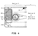
- the section of the tape cartridge which registers the tape with respect to the disc drive heads, and is inserted into the disc drive to gain access to the heads, is shown in Figures 2-4 and is referred to as Section A.
- the section of the tape cartridge used to store and feed the tape is referred to as the feed/storage section.
- the feed/storage section in a tape cartridge embodiment utilizing a reversing length of tape is shown in Figure 5 and is referred to as Section B.
- the feed/storage section in an embodiment utilizing an endless loop of tape is shown in Figure 8 and is referred to as Section C.
- the first tape cartridge embodiment is comprised of Sections A and B
- the second embodiment is comprised of Sections A and C.
- the “disc drive head” is the mechanism for reading and/or writing data on an associated data recording medium.
- the tape typically has a "length”, “width”, and “thickness” such that its length (typically several feet) is much greater than its width (of the order of 3/4 inch or 19mm), and its width is much greater than its thickness (of the order of 0.0005 inch or 12.7 x 10 ⁇ 3mm). Therefore the tape can be viewed as a two dimensional surface extending in the directions of its length and width.
- “Feeding” a tape shall mean to translate it in the direction of its length.
- the "plane of the tape” shall mean that plan that is tangent to this two dimensional surface at that point.
- a “tape guide” shall be any element which modifies the "plane of the tape” or the position of the edge of the tape as the tape feeds over the guide. If a tape guide modifies the plane of the tape such that the tape path is twisted around the tape guide, the tape guide shall be referred to as "twist tape guide.”
- the tape media used is nominally .75(19mm) inches wide. This allows one of the disc drive heads to access 80 tracks, the maximum number used by standard 3.5 inch disc drives.
- the tape has a magnetic coating with a coercivity and thickness capable of supporting magnetic transitions written by the disc drive head at its normal data rate, at the speed which the tape is traveling.
- a back coating may be used if it provides benefits (e.g., reduced friction, increase wear resistance and/or reduce static electric charge) to the means for tape feed, storage, or registration. If the tape is stored wrapped upon itself, this back coating must be non-magnetic to avoid print over.
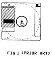
- Figure 1 is at bottom view of a standard 3.5 inch microfloppy disc cassette.
- the dashed circle represents the disc media inside the cassette.
- the hatched area is an autoshutter. This is a protective cover that slides when the disc cassette is inserted into the disc drive, so an opening in the autoshutter is aligned with a matching opening in the casette, allowing the disc drive heads to access the disc media.
- the shutter is shown in the open position.
- the half filled rectangle in the top right corner of the cassette in Figure 1 is a write protect switch. This switch position is read by a sensor in the disc drive, and allows the disc drive to recognize a write protected disc cassette.
- Section A of the tape cartridge. Because Section A is intended to fit inside a 3.5 inch microfloppy disc drive, its dimensions must be suitably close to those of a 3.5 inch microfloppy disc cassette (90 mm wide, 94 mm long, and 3.3 mm thick), so that it fits properly with the cassette loading mechanism of the disc drive. In general, this requires that section A have disclike shape suitable for fitting though the slot in the front of typical disc drives.
- the tape media 20 enters Section A from the tape supply location 21. Tape is fed from location 21 to twist tape guide 22, past a location L at which data is written to or read from the tape by the disc drive head(s) (somewhere along dotted line 25), to twist tape guide 23, and out of Section A to the tape take-up location 24. In general, location L is the location at which reading and writing occur and in some disc drives, such as optical disc drives, may not be adjacent to the read/write head(s).
- the tape is fed from supply location 21 to take-up location 24.
- the supply and take-up then switch positions. This reverses the direction of the tape feed to rewind the tape. Once the tape is rewound, the supply and take-up revert to their original positions and the cycle is repeated. The means of this switching will be outlined in the discussion of Section B.
- Twist tape guides 22 and 23 are oriented at nominally 45 degrees to the direction of feed of the tape.
- the tape wraps substantially 180 degrees around the guide in a helical fashion, which changes the path of feed of the tape by 90 degrees and rotates the normal to the plane of the tape by 180 degrees.
- This manner of guiding the tape within Section A keeps the tape within a disclike region that has a size and shape that enable Section A to fit through the slot in the front of many typical disc drives.
- These guides enable the tape to enter section A, gain proper access to location L and exist section A while remaining within the volume defined by Section A. In this manner, the tape passes across the disc drive heads, which are located along line 25, with a motion similar to that of the disc media.
- tape guides 26 provide a reference edge which acts to register the tape, and/or provide a wrap angle to change the plane of the tape.
- These tape guides 26 are in several locations: between tape supply location 21 and twist tape guide 22; between twist tape guides 22 and 23; and between twist tape guide 23 and tape take-up location 24.
- a force is exerted on the tape to constrain one of its edges to the reference edge of the tape guide 26. This force may be exerted on the tape either by deliberate misalignment of twist tape guides 22 and 23, by the shape of twist tape guides 22, 23, and/or tape guide 26, and/or by a spring loaded surface acting on the nonreference edge of the tape.
- All of the tape guides and drive elements which contact the tape are fabricated from a non-magnetic material such as non-magnetic stainless steel or a ceramic material.
- the power to feed the tape is derived from the disc drive spindle motor.
- a cyclindrical hub 27 containing a circular hole 43 at the center of the hub and a second hole 44 away from the center of the hub.
- hole 43 is located onto the circular shaft of the disc drive spindle motor.
- a spring loaded pin from the motor hub assembly extends into hole 44.
- a hole 42 in the lower surface of the protective shell 29 allows the spindle motor hub assembly to access hub 27. Openings 212 in both the upper and lower surfaces of shell 29 provide access to the tape along line 25 by the disc drive heads. These openings 212 are protected by a sliding piece 40 which contains openings 41 in its upper and lower surfaces. During use of the tape cartridge, sliding piece 40 is located such that openings 41 are positioned adjacent to openings 212. This sliding piece is essentially identical in appearance and function to the "auto shutter" on a 3.5 inch microfloppy disc cassette and movement of sliding piece 40 is effected in the same manner as for the auto shutter.
- a write protect switch 45 operates in a similar manner to the write protect switch of a disc cassette, and interacts identically with the sensor in the disc drive that determines the state of this switch.
- the protective shell also includes a rotary bearing 28 whose inner race rotates with hub 27 and whose outer race remains fixed, thereby isolating the rotary motion of hub 27 from the stationery part of the tape cartridge.
- the tape cartridge includes a pair of holes 210 and 211 in the bottom surface of the protective shell 29 that are positioned to fit over the pair of pins in the disc drive unit.
- the slot shaped hole 211 provides a tight clearance fit over the associated pin in the disc drive. Holes 211 and 43 provide the angular and vertical reference for the tape cartridge. Hole 210 provides a loose clearance fit over the associated pin in the disc drive and provides only vertical reference for the tape cartridge. The remainder of the translational location is determined by the right clearance fit of hole 43 to the disc drive spindle motor's circular shaft. Two additional pins located inside the disc drive near the disc drive's cassette opening also provide vertical support to either a microfloppy disc cassette or the tape cartridge.
- tape guides 22, 23 and 26 must be accurately positioned with respect to these registration holes.
- the runout of bearing 28 must also be accounted for in tolerance accumulation to ensure that tape 20 is accurately aligned with the disc drive heads.
- the disc drive spindle motor is used as a power source to feed the tape.
- Hub 27 contains a pulley which drives belt 213.
- Belt 213 is used to transmit power from hub 27 to the tape driving element in either Section B or Section C. If the disc drive spindle motor has insufficient power or is otherwise unsuitable for driving the tape, either of these embodiments may function in an identical fashion using a dedicated motor contained within the tape cartridge, or some other suitable power source, to drive the tape.
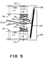
- a feed/storage section, denoted as Section B, utilizing a pair of supply/takeup spools 51 and 52 is shown in Figure 5.
- One end of the tape media 20 is fixed onto spool 51, and the other is fixed onto spool 52.
- the tape media is alternately wound from one spool, that serves as a supply spool, through Section A, and onto the other spool, which serves as a take-up spool.
- the tape supply location 21 is on spool 51, while spool 52 is being driven to act as the tape take-up location 24.
- This is the direction of tape travel in which data is written or read.
- standard 3.5 inch disc drive heads are capable of data transfer only when the media is traveling in one direction. Hence the other direction of tape travel is for rewind. If future changes in head design allow for bi-directional data transfer, both directions of tape travel will accommodate data transfer.
- power is derived from the disc drive spindle motor via belt 213. Because the spindle motor turns only in one direction, the direction of tape travel must be reversed by means of a toggling clutch located on a spool shaft 50 on which tape spools 51 and 52 are free to rotate.
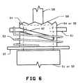
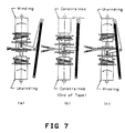
- a sliding pulley 53 which is driven by belt 213, is engaged by means of teeth 60 (as illustrated in greater detail in Figure 6) with the teeth in either of a pair of helical sliders 54 and 55.
- Each helical slider is rotatably mounted on shaft 50 and is connected by a torsion spring 63 to an associated one of spools 51 and 52.
- FIG. 6 shows a detail of one of the helical sliders 54 and 55.
- Each helical slider has a hollow sleeve that can rotate about an extension 64 of its respective spool, 51 or 52.
- a pair of pins 61 are rigidly attached to extension 64 and pass through a helical slot 62 in the slider.
- shaft 50 is rigidly mounted to shell 211, as the helical slide rotates, it unscrews itself and the sliding pulley away from the take-up spool by slot 62 riding on the pins 61.
- the angle of the teeth 60 is steeper than that of the helical slot 62, to ensure that the teeth do not disengage preferentially to the helical translation of the pin/slot combination.
- an over-center device 56 is activated. This over-center device 56 is spring loaded by spring 57, and is coupled to the sliding pulley by roller 58. The over-centre device pushes the sliding pulley toward the other spool, which then engages its teeth with the new take-up spool and helical slider.
- FIGS 7a-c illustrate this process. This action frees the old helical slider, which is then retracted to the old take-up spool by means of the spring 63 attached at one end to the pin 61 and at the other end to a flange 65 which is part of the helical slider 54 or 55.
- This tape feed reversing process repeats itself each time the end of the tape is reached.
- the feed/storage embodiment denoted as Section C is shown in Figure 8.
- the tape media 20 enters Section C from Section A at location 24.
- the tape wraps around twist guide 80 in such a manner as to execute a half twist. Orientation of the tape is changed from nominally co-planar with Section A upon entering the guide, to nominally on its edge, traveling in a nearly transverse direction, as it exits the guide.
- a looping arrow in Figure 8 shows this change in direction.
- Twist guide 81 is identical to 80, however it is oriented to perform the inverse directional change on the tape.
- Figure 9 is a detail of these guides.
- the tape feeds on its edge onto the outside of a spool of tape defined by the perimeter of rollers 8285. As the tape is fed, it continually spirals inward until the inside strand of tape wraps more completely around roller 84, and into the center of the spool.
- This embodiment shows a capstan 86 deriving power from the disc drive spindle motor via belt 213 wrapped around a pulley fixed to the capstan.
- An idling pinch roller 87 is supported by idler arm 88.
- the idler arms pivots about pin 89 such that the pinch roller is loaded against the capstan by spring 810.
- a friction drive is provided to feed the tape.
- the tape wraps around twist guide 81, which reorients the tape nominally co-planar with Section A as it exits Section C.
- the tape travels in one direction only, therefore no reversing clutches are required.
- This scheme is inherently more time efficient with current 3.5 inch microfloppy disc drives because no time is required to rewind the tape. Due to the extra tape twisting required however, and the friction that may be associated with guiding this twisting, a more powerful motor may be required than in embodiments utilizing a reversing length of tape.
- Other endless loop embodiments may differ in the relative location of the drive element, the spool hub(s) drive, and the geometry of the tape twisting action. However all of these embodiments are basically comprised the same functional elements.
Landscapes
- Optical Record Carriers And Manufacture Thereof (AREA)
- Wrappers (AREA)
- Recording Or Reproducing By Magnetic Means (AREA)
- Adhesive Tapes (AREA)
- Feeding And Guiding Record Carriers (AREA)
- Replacement Of Web Rolls (AREA)
- Packaging Of Annular Or Rod-Shaped Articles, Wearing Apparel, Cassettes, Or The Like (AREA)
- Management Or Editing Of Information On Record Carriers (AREA)
Claims (13)
- Eine mit einer Plattenantriebseinheit in einen wirksamen Eingriff bringbare Bandkassette zum Übertragen von Daten zwischen einem Band (20) der Bandkassette und einem Übertragerkopf der Plattenantriebseinheit, wobei die Kassette eine Bandzuführeinrichtung (213, 53 bis 55) zum Zuführen des Bandes (20) und eine Speichereinrichtung (51, 52) zum speichern des Bandes (20) aufweist, dadurch gekennzeichnet, daß das Band (20) der Kassette eine Form aufweist, die es ermöglicht, Daten durch den Kopf der Plattenantriebseinheit direkt auf das Band (20) zu schreiben und/oder von diesem zu lesen, und daß die Kassette mit einer Lokalisierungseinrichtung (22, 23, 26, 43, 210, 211) zum Registrieren eines Teiles des Bandes (20) an einem bestimmten Ort (L), an dem Daten direkt zwischen dem Band (20) und dem Übertragerkopf übertragen werden können, versehen ist.
- Eine Bandkassette gemäß Anspruch 1, bei der die Lokalisierungseinrichtung aufweist:
Eine Kassettenausrichteinrichtung (43, 210, 211) zum Ausrichten der Bandkassette mit der Plattenantriebseinheit, wenn die Bandkassette in die Plattenantriebseinheit geladen wird; und
eine Führungseinrichtung (22, 23, 26) zum Führen des Bandes (20) innerhalb der Bandkassette derart, daß bei Ausrichtung der Bandkassette mit der Plattenantriebseinheit das Band (20) an dem vorbestimmten Ort (L) registriert wird. - Eine Bandkassette gemäß Anspruch 2, ferner mit:
Einem Schutzgehäuse (29), welche das Band (20) umgibt, wobei das Gehäuse einen Bodenabschnitt hat, der darin wenigstens zwei Löcher (43, 211) aufweist, die derart angeordnet sind, daß bei der in der Plattenantriebseinheit geladenen Kassette jedes der Löcher (43, 211) über einen entsprechenden Vorsprung in der Plattenantriebseinheit paßt und die Bandkassette mit der Einheit ausrichtet. - Eine Bandkassette gemäß Anspruch 3 zur Verwendung mit einer eine Motorwelle aufweisenden Plattenantriebseinheit, bei der eines (43) der Löcher in dem Bodenabschnitt des Gehäuses (29) angeordnet ist, um über die Motorwelle zu passen, wodurch die Motorwelle als einer der vorbestimmten Antriebsvorsprünge wirkt, die verwendet werden, um die Bandkassette mit dem vorbestimmten Ort (L) auszurichten.
- Eine Bandkassette gemäß Anspruch 2, bei der die Bandkassette einen Abschnitt (A) hat, der in die Plattenantriebseinheit einsetzbar ist, wobei das Band (20) innerhalb des Abschnittes (A) in einem im wesentlichen planen Bereich aufgenommen ist.
- Eine Bandkassette gemäß Anspruch 5, bei der innerhalb des Abschnittes (A) die Führungseinrichtung eine Mehrzahl von Verdrehungsbandführungen (22, 23) aufweist, wobei das Band (20) sich um jede der Verdrehungsbandführungen (22, 23) um im wesentlichen 180° herumwickelt, um die Zuführungsrichtung des Bandes (20) zu ändern und um die Senkrechte auf die Ebene des Bandes um im wesentlichen 180° zu drehen.
- Eine Bandkassette gemäß Anspruch 1, bei der die Speichereinrichtung eine erste Spule (51) und eine zweite Spule (52) umfaßt, zwischen denen das Band (20) gewickelt ist.
- Eine Bandkassette gemäß Anspruch 1, bei der die Speichereinrichtung eine Einrichtung (82 bis 85) zum Speichern des Bandes als endlose Bandschleife aufweist.
- Eine Bandkassette gemäß Anspruch 1, bei der die Bandzuführeinrichtung aufweist:
Eine Bandantriebseinrichtung (51, 52), die in Kontakt mit dem Band (20) steht, um dieses anzutreiben; und
ein Getriebe (213, 53 bis 55) zum Koppeln der Leistung von einem Motor an die Bandantriebseinrichtung (51, 52). - Eine Bandkassette gemäß Anspruch 9, bei der das Getriebe eine Kupplung (54, 55, 56) zum Umkehren der Richtung, in die das Band (20) nach dem vorbestimmten Ort (L) geführt wird, aufweist.
- Eine Bandkassette gemäß Anspruch 9 oder Anspruch 10, bei der das Getriebe angeordnet ist, um Leistung zu der Bandantriebseinrichtung von einem Antriebsmotor der Plattenantriebseinheit zu übertragen.
- Eine Bandkassette gemäß Anspruch 9 oder Anspruch 10, ferner mit einem Bandkassettenmotor, wobei das Getriebe angeordnet ist, um Leistung von dem Bandkassettenmotor zu der Bandantriebseinrichtung zu übertragen.
- Eine Bandkassette gemäß einem der Ansprüche 9 bis 12, bei der die Bandantriebseinrichtung eine erste Spule (51) und eine zweite Spule (52) aufweist, wobei die Spulen drehbar mittels des Getriebes antreibbar sind, um das Band (20) von einer Spule auf die andere zu wickeln, wobei die Spulen als Bandspeichereinrichtung wirken.
Priority Applications (1)
| Application Number | Priority Date | Filing Date | Title |
|---|---|---|---|
| AT86301668T ATE76532T1 (de) | 1985-03-18 | 1986-03-10 | Bandkassette. |
Applications Claiming Priority (2)
| Application Number | Priority Date | Filing Date | Title |
|---|---|---|---|
| US06/713,162 US4796136A (en) | 1985-03-18 | 1985-03-18 | Disc drive compatible cartridge tape |
| US713162 | 1985-03-18 |
Publications (3)
| Publication Number | Publication Date |
|---|---|
| EP0195571A2 EP0195571A2 (de) | 1986-09-24 |
| EP0195571A3 EP0195571A3 (en) | 1988-08-03 |
| EP0195571B1 true EP0195571B1 (de) | 1992-05-20 |
Family
ID=24865017
Family Applications (1)
| Application Number | Title | Priority Date | Filing Date |
|---|---|---|---|
| EP86301668A Expired - Lifetime EP0195571B1 (de) | 1985-03-18 | 1986-03-10 | Bandkassette |
Country Status (10)
| Country | Link |
|---|---|
| US (1) | US4796136A (de) |
| EP (1) | EP0195571B1 (de) |
| JP (1) | JPH0743904B2 (de) |
| KR (1) | KR930011697B1 (de) |
| AT (1) | ATE76532T1 (de) |
| AU (1) | AU568968B2 (de) |
| CA (1) | CA1310408C (de) |
| DE (1) | DE3685354D1 (de) |
| HK (1) | HK87692A (de) |
| SG (1) | SG94492G (de) |
Families Citing this family (14)
| Publication number | Priority date | Publication date | Assignee | Title |
|---|---|---|---|---|
| US4896237A (en) * | 1985-08-30 | 1990-01-23 | Sony Corporation | Magnetic tape cartridge compatible with disk drive and tape drive mechanism therefor |
| JPS62157313A (ja) * | 1985-12-28 | 1987-07-13 | ソニー株式会社 | 往復記録再生ヘツド |
| JPS62113480U (de) * | 1985-12-28 | 1987-07-18 | ||
| JPH077588B2 (ja) * | 1985-12-28 | 1995-01-30 | ソニー株式会社 | テ−プカセツトのセンタコア |
| AU601385B2 (en) * | 1985-12-28 | 1990-09-13 | Hewlett-Packard Company | Disk-drive-compatible magnetic tape cartridge with tape-positioning guide for accurately positioning magnetic tape with respect to disk drive head |
| US4888659A (en) * | 1987-01-16 | 1989-12-19 | Hewlett-Packard Company | Tape cartridge for use in disc drive |
| EP0274565B1 (de) * | 1987-01-16 | 1992-01-22 | Hewlett-Packard Company | Bandkassette zur Verwendung in einem Plattengerät |
| WO1988006793A1 (en) * | 1987-02-27 | 1988-09-07 | Baker James W | Magnetic tape backup device for use with a floppy disk drive |
| US4890179A (en) * | 1987-02-27 | 1989-12-26 | Baker James W | Magnetic tape backup device for use with a floppy disk drive |
| US5224216A (en) * | 1988-10-28 | 1993-06-29 | Gordon Alastair T | Computer diskette drive communication interface |
| US6639753B1 (en) | 2000-09-01 | 2003-10-28 | Hewlett-Packard Development Company, L.P. | Method of forming a head assembly, a head assembly, and a linear tape drive |
| US6545865B2 (en) | 2001-07-13 | 2003-04-08 | International Business Machines Corporation | Shock mount for a device packaged in a portable cartridge |
| GB2407659A (en) * | 2003-10-31 | 2005-05-04 | Hewlett Packard Development Co | Disaster recovery using multiple boot images held on a sequential storage device |
| TWM270466U (en) * | 2004-12-28 | 2005-07-11 | Accesstek Inc | Sucking-type optical disk drive with transmission belt |
Family Cites Families (17)
| Publication number | Priority date | Publication date | Assignee | Title |
|---|---|---|---|---|
| US2694110A (en) * | 1947-06-27 | 1954-11-09 | Int Electronics Co | Equipment for use with magnetic tape records |
| GB636993A (en) * | 1948-01-26 | 1950-05-10 | Hartley Electromotives Ltd | Improvements in or relating to sound recording and reproducing apparatus |
| FR1181649A (fr) * | 1956-11-16 | 1959-06-17 | W H Sanders Electronics Ltd | Perfectionnement aux appareils magnétiques pour l'enregistrement et la reproduction des sons |
| US3285527A (en) * | 1963-11-21 | 1966-11-15 | Jr Howard W Cole | Endless tape winding devices |
| DE1572496A1 (de) * | 1967-12-30 | 1970-02-19 | Wolf Rosenthal | Ein Abspielgeraet passend fuer Tonbandspulen und Schallplatten |
| US3624310A (en) * | 1969-11-21 | 1971-11-30 | Motorola Inc | Tape player phonograph adapter permitting operation of tape cartridges or cassettes on conventional phonograph |
| FR2161529A5 (de) * | 1971-11-24 | 1973-07-06 | Gilbraut Clement | |
| DE2357812A1 (de) * | 1973-11-20 | 1975-05-28 | Trend Inst Anstalt | Kassette fuer bild- und tontraeger |
| US4031555A (en) * | 1975-10-20 | 1977-06-21 | Hughes Theodore R | Reel-to-reel tape to tape cartridge adapter |
| US4511940A (en) * | 1981-10-05 | 1985-04-16 | Clarion Co., Ltd. | Tape player having motor-driven tape-pack loading mechanism |
| US4498112A (en) * | 1982-03-22 | 1985-02-05 | Data Electronics, Inc. | Tape cartridge receptacle |
| US4514775A (en) * | 1982-05-03 | 1985-04-30 | Mfe Corporation | Streaming cassette tape transport |
| JPS59193587A (ja) * | 1983-04-15 | 1984-11-02 | Olympus Optical Co Ltd | 磁気記録媒体収納カセツト |
| JPS6242176U (de) * | 1985-08-30 | 1987-03-13 | ||
| US4896237A (en) * | 1985-08-30 | 1990-01-23 | Sony Corporation | Magnetic tape cartridge compatible with disk drive and tape drive mechanism therefor |
| JPH077588B2 (ja) * | 1985-12-28 | 1995-01-30 | ソニー株式会社 | テ−プカセツトのセンタコア |
| AU601385B2 (en) * | 1985-12-28 | 1990-09-13 | Hewlett-Packard Company | Disk-drive-compatible magnetic tape cartridge with tape-positioning guide for accurately positioning magnetic tape with respect to disk drive head |
-
1985
- 1985-03-18 US US06/713,162 patent/US4796136A/en not_active Expired - Lifetime
- 1985-06-27 CA CA000485679A patent/CA1310408C/en not_active Expired - Lifetime
- 1985-07-25 KR KR1019850005314A patent/KR930011697B1/ko not_active Expired - Lifetime
- 1985-09-27 JP JP60214361A patent/JPH0743904B2/ja not_active Expired - Lifetime
-
1986
- 1986-01-31 AU AU52887/86A patent/AU568968B2/en not_active Ceased
- 1986-03-10 AT AT86301668T patent/ATE76532T1/de not_active IP Right Cessation
- 1986-03-10 EP EP86301668A patent/EP0195571B1/de not_active Expired - Lifetime
- 1986-03-10 DE DE8686301668T patent/DE3685354D1/de not_active Expired - Lifetime
-
1992
- 1992-09-17 SG SG944/92A patent/SG94492G/en unknown
- 1992-11-12 HK HK876/92A patent/HK87692A/en not_active IP Right Cessation
Also Published As
| Publication number | Publication date |
|---|---|
| KR860007647A (ko) | 1986-10-15 |
| DE3685354D1 (de) | 1992-06-25 |
| EP0195571A2 (de) | 1986-09-24 |
| SG94492G (en) | 1992-12-04 |
| JPH0743904B2 (ja) | 1995-05-15 |
| KR930011697B1 (ko) | 1993-12-18 |
| ATE76532T1 (de) | 1992-06-15 |
| HK87692A (en) | 1992-11-20 |
| JPS61214188A (ja) | 1986-09-24 |
| EP0195571A3 (en) | 1988-08-03 |
| AU5288786A (en) | 1986-09-25 |
| US4796136A (en) | 1989-01-03 |
| AU568968B2 (en) | 1988-01-14 |
| CA1310408C (en) | 1992-11-17 |
Similar Documents
| Publication | Publication Date | Title |
|---|---|---|
| EP0710391B1 (de) | Rotierende bandrandführung | |
| US6188532B1 (en) | Backward compatible head and head positioning assembly for a linear digital tape drive | |
| US4796136A (en) | Disc drive compatible cartridge tape | |
| JP5337160B2 (ja) | 読み書きヘッドと可撓性データ記憶媒体との間の位置合わせ不良を調整するためのシステム | |
| US5585978A (en) | Arcuate scan tape drive | |
| CN114600189B (zh) | 具有用于支撑带卷轴对的可移除安装件的多卷轴带记录装置 | |
| US6241171B1 (en) | Leaderless tape drive | |
| EP0929071B1 (de) | Mehrfachbandkassette und Laufwerkssytem in dem Bänder aus der Kassette herausgezogen werden | |
| EP0003444B1 (de) | Verfahren und Apparat zur Aufzeichnung von Videosignalen | |
| JPS6011559B2 (ja) | 位置決め機構 | |
| EP0274565B1 (de) | Bandkassette zur Verwendung in einem Plattengerät | |
| US7440231B2 (en) | Single reel tape cartridge having guide surface | |
| EP1746592A2 (de) | Kassettenlaufwerk mit verbessertem Bandlauf und entsprechende Verfahren | |
| US4888659A (en) | Tape cartridge for use in disc drive | |
| CA1319426C (en) | Disk-drive-compatible magnetic tape cartridge with tape-positioning guide for accurately positioning magnetic tape with respect to disk drive head | |
| US4123789A (en) | Magnetic tape storage and transport cartridge and mechanisms therefor | |
| JP3590177B2 (ja) | テープ駆動装置 | |
| CN86103068A (zh) | 可与磁盘驱动器兼容的盒式磁带机 | |
| JP3794155B2 (ja) | 磁気記録再生装置及び磁気記録再生方法 | |
| EP0837466B1 (de) | Bandantrieb zur Benutzung mit Bandkassetten | |
| US7057846B2 (en) | Recording/reproducing apparatus with reduced number of guides posts | |
| JPS6251084A (ja) | テ−プカセツト | |
| JP2005044484A (ja) | 磁気記録再生装置 | |
| JPS581855A (ja) | 磁気カ−ド読み取り装置 | |
| JPH11175937A (ja) | 記録再生装置及び記録再生方法 |
Legal Events
| Date | Code | Title | Description |
|---|---|---|---|
| PUAI | Public reference made under article 153(3) epc to a published international application that has entered the european phase |
Free format text: ORIGINAL CODE: 0009012 |
|
| AK | Designated contracting states |
Kind code of ref document: A2 Designated state(s): AT DE FR GB IT SE |
|
| PUAL | Search report despatched |
Free format text: ORIGINAL CODE: 0009013 |
|
| AK | Designated contracting states |
Kind code of ref document: A3 Designated state(s): AT DE FR GB IT SE |
|
| 17P | Request for examination filed |
Effective date: 19880816 |
|
| 17Q | First examination report despatched |
Effective date: 19900517 |
|
| GRAA | (expected) grant |
Free format text: ORIGINAL CODE: 0009210 |
|
| ITF | It: translation for a ep patent filed | ||
| AK | Designated contracting states |
Kind code of ref document: B1 Designated state(s): AT DE FR GB IT SE |
|
| PG25 | Lapsed in a contracting state [announced via postgrant information from national office to epo] |
Ref country code: SE Effective date: 19920520 Ref country code: AT Effective date: 19920520 |
|
| REF | Corresponds to: |
Ref document number: 76532 Country of ref document: AT Date of ref document: 19920615 Kind code of ref document: T |
|
| REF | Corresponds to: |
Ref document number: 3685354 Country of ref document: DE Date of ref document: 19920625 |
|
| ET | Fr: translation filed | ||
| PLBE | No opposition filed within time limit |
Free format text: ORIGINAL CODE: 0009261 |
|
| STAA | Information on the status of an ep patent application or granted ep patent |
Free format text: STATUS: NO OPPOSITION FILED WITHIN TIME LIMIT |
|
| ITTA | It: last paid annual fee | ||
| 26N | No opposition filed | ||
| REG | Reference to a national code |
Ref country code: GB Ref legal event code: 732E |
|
| REG | Reference to a national code |
Ref country code: FR Ref legal event code: TP |
|
| REG | Reference to a national code |
Ref country code: GB Ref legal event code: IF02 |
|
| PGFP | Annual fee paid to national office [announced via postgrant information from national office to epo] |
Ref country code: GB Payment date: 20050302 Year of fee payment: 20 |
|
| PGFP | Annual fee paid to national office [announced via postgrant information from national office to epo] |
Ref country code: FR Payment date: 20050321 Year of fee payment: 20 |
|
| PGFP | Annual fee paid to national office [announced via postgrant information from national office to epo] |
Ref country code: IT Payment date: 20050329 Year of fee payment: 20 |
|
| PGFP | Annual fee paid to national office [announced via postgrant information from national office to epo] |
Ref country code: DE Payment date: 20050502 Year of fee payment: 20 |
|
| PG25 | Lapsed in a contracting state [announced via postgrant information from national office to epo] |
Ref country code: GB Free format text: LAPSE BECAUSE OF EXPIRATION OF PROTECTION Effective date: 20060309 |
|
| REG | Reference to a national code |
Ref country code: GB Ref legal event code: PE20 |