EP0195636A2 - Armbanduhr mit Druckmessfühler - Google Patents
Armbanduhr mit Druckmessfühler Download PDFInfo
- Publication number
- EP0195636A2 EP0195636A2 EP86301936A EP86301936A EP0195636A2 EP 0195636 A2 EP0195636 A2 EP 0195636A2 EP 86301936 A EP86301936 A EP 86301936A EP 86301936 A EP86301936 A EP 86301936A EP 0195636 A2 EP0195636 A2 EP 0195636A2
- Authority
- EP
- European Patent Office
- Prior art keywords
- wristwatch according
- depth
- pressure
- wristwatch
- pressure sensor
- Prior art date
- Legal status (The legal status is an assumption and is not a legal conclusion. Google has not performed a legal analysis and makes no representation as to the accuracy of the status listed.)
- Granted
Links
- XLYOFNOQVPJJNP-UHFFFAOYSA-N water Substances O XLYOFNOQVPJJNP-UHFFFAOYSA-N 0.000 claims abstract description 34
- 230000004044 response Effects 0.000 claims abstract description 13
- 230000001681 protective effect Effects 0.000 claims description 17
- 230000008859 change Effects 0.000 claims description 13
- 238000005259 measurement Methods 0.000 claims description 10
- 239000011347 resin Substances 0.000 claims description 10
- 229920005989 resin Polymers 0.000 claims description 10
- 239000004020 conductor Substances 0.000 claims description 7
- 239000004973 liquid crystal related substance Substances 0.000 claims description 5
- 210000002858 crystal cell Anatomy 0.000 claims description 4
- 239000004065 semiconductor Substances 0.000 claims description 4
- 230000006872 improvement Effects 0.000 claims description 2
- 239000000463 material Substances 0.000 claims description 2
- 238000007789 sealing Methods 0.000 claims 1
- 230000009189 diving Effects 0.000 abstract description 50
- 230000006870 function Effects 0.000 description 38
- XUIMIQQOPSSXEZ-UHFFFAOYSA-N Silicon Chemical compound [Si] XUIMIQQOPSSXEZ-UHFFFAOYSA-N 0.000 description 15
- 229910052710 silicon Inorganic materials 0.000 description 15
- 239000010703 silicon Substances 0.000 description 15
- 210000004027 cell Anatomy 0.000 description 14
- 238000001514 detection method Methods 0.000 description 8
- 238000010586 diagram Methods 0.000 description 7
- 239000010410 layer Substances 0.000 description 7
- 230000002159 abnormal effect Effects 0.000 description 6
- 230000003247 decreasing effect Effects 0.000 description 6
- 210000004247 hand Anatomy 0.000 description 5
- 238000006243 chemical reaction Methods 0.000 description 4
- 238000010276 construction Methods 0.000 description 4
- 238000009413 insulation Methods 0.000 description 4
- 239000013078 crystal Substances 0.000 description 3
- 239000000428 dust Substances 0.000 description 3
- 239000011521 glass Substances 0.000 description 3
- 238000012856 packing Methods 0.000 description 3
- 239000004576 sand Substances 0.000 description 3
- 239000013535 sea water Substances 0.000 description 3
- 230000032683 aging Effects 0.000 description 2
- 238000004140 cleaning Methods 0.000 description 2
- 230000007246 mechanism Effects 0.000 description 2
- 230000002265 prevention Effects 0.000 description 2
- RZVAJINKPMORJF-UHFFFAOYSA-N Acetaminophen Chemical compound CC(=O)NC1=CC=C(O)C=C1 RZVAJINKPMORJF-UHFFFAOYSA-N 0.000 description 1
- 102100037114 Elongin-C Human genes 0.000 description 1
- 101001011859 Homo sapiens Elongin-A Proteins 0.000 description 1
- 101001011846 Homo sapiens Elongin-B Proteins 0.000 description 1
- 101000881731 Homo sapiens Elongin-C Proteins 0.000 description 1
- 101000836005 Homo sapiens S-phase kinase-associated protein 1 Proteins 0.000 description 1
- 241000219470 Mirabilis Species 0.000 description 1
- 230000005856 abnormality Effects 0.000 description 1
- 239000012790 adhesive layer Substances 0.000 description 1
- 230000002411 adverse Effects 0.000 description 1
- 238000009530 blood pressure measurement Methods 0.000 description 1
- 239000003990 capacitor Substances 0.000 description 1
- 239000000919 ceramic Substances 0.000 description 1
- 230000009194 climbing Effects 0.000 description 1
- 238000012937 correction Methods 0.000 description 1
- 238000006073 displacement reaction Methods 0.000 description 1
- 230000000694 effects Effects 0.000 description 1
- 238000011010 flushing procedure Methods 0.000 description 1
- 238000003780 insertion Methods 0.000 description 1
- 230000037431 insertion Effects 0.000 description 1
- 230000007257 malfunction Effects 0.000 description 1
- 238000000034 method Methods 0.000 description 1
- 230000008569 process Effects 0.000 description 1
- 239000005297 pyrex Substances 0.000 description 1
- 230000035945 sensitivity Effects 0.000 description 1
- 238000004804 winding Methods 0.000 description 1
- 210000000707 wrist Anatomy 0.000 description 1
Images


Classifications
-
- G—PHYSICS
- G04—HOROLOGY
- G04G—ELECTRONIC TIME-PIECES
- G04G21/00—Input or output devices integrated in time-pieces
- G04G21/02—Detectors of external physical values, e.g. temperature
-
- B—PERFORMING OPERATIONS; TRANSPORTING
- B63—SHIPS OR OTHER WATERBORNE VESSELS; RELATED EQUIPMENT
- B63C—LAUNCHING, HAULING-OUT, OR DRY-DOCKING OF VESSELS; LIFE-SAVING IN WATER; EQUIPMENT FOR DWELLING OR WORKING UNDER WATER; MEANS FOR SALVAGING OR SEARCHING FOR UNDERWATER OBJECTS
- B63C11/00—Equipment for dwelling or working underwater; Means for searching for underwater objects
- B63C11/02—Divers' equipment
-
- G—PHYSICS
- G01—MEASURING; TESTING
- G01C—MEASURING DISTANCES, LEVELS OR BEARINGS; SURVEYING; NAVIGATION; GYROSCOPIC INSTRUMENTS; PHOTOGRAMMETRY OR VIDEOGRAMMETRY
- G01C5/00—Measuring height; Measuring distances transverse to line of sight; Levelling between separated points; Surveyors' levels
- G01C5/06—Measuring height; Measuring distances transverse to line of sight; Levelling between separated points; Surveyors' levels by using barometric means
-
- G—PHYSICS
- G04—HOROLOGY
- G04B—MECHANICALLY-DRIVEN CLOCKS OR WATCHES; MECHANICAL PARTS OF CLOCKS OR WATCHES IN GENERAL; TIME PIECES USING THE POSITION OF THE SUN, MOON OR STARS
- G04B47/00—Time-pieces combined with other articles which do not interfere with the running or the time-keeping of the time-piece
- G04B47/06—Time-pieces combined with other articles which do not interfere with the running or the time-keeping of the time-piece with attached measuring instruments, e.g. pedometer, barometer, thermometer or compass
- G04B47/066—Time-pieces combined with other articles which do not interfere with the running or the time-keeping of the time-piece with attached measuring instruments, e.g. pedometer, barometer, thermometer or compass with a pressure sensor
Definitions
- the present invention relates to an electronic wristwatch having a pressure sensor.
- a pressure sensor can be used as a depth or altitude meter.
- a depth meter is an essential piece of equipment for divers.
- Various kinds of depth meters are available on the market.
- the depth meters are all separate items. Namely, there has been no scuba-diving or snorkeling wristwatch which has a depth meter integrally and functionally incorporated therein.
- Known depth meters come in two types: a mechanical type, which can indicate the depth of diving but cannot perform other functions, such as recording of the diving time, warning of the diving time after a preset time elapses, and/or warning of the depth when deeper than a preset level, contributing to safe diving and an electronic type, which can also perform various functions such as those mentioned above.
- the electronic type depth meter is rather complex in construction which sometimes results in malfunctions during diving.
- the depth meter In providing a wristwatch which has a depth meter (or an altitude meter) integrally and functionally incorporated therein, it is very important to prevent the depth meter from interferring with the existing crown and existing pushbutton(s) for switching various functions provided on the periphery of a watch case and also to enable the indicated or displayed depth to be easily seen without decreasing the visible field of a dial of the watch.
- the depth meter since the depth meter senses pressure, the depth meter has to be able to correctly receive the pressure of the water, to fully resist it, and to be completely sealed so as not to allow the water and the water pressure to affect the internal movement, internal electronic devices, etc. of the watch.
- the present invention aims at the provision of a wristwatch with a pressure sensor which does not interfere with external pushbuttons of the wristwatch, has a high pressure resistance, is highly sealed, and enables easy viewing of the measurement, particularly even in the water without substantially decreasing the visible field of the watch dial.
- Another object of the present invention is to provide a wristwatch with a pressure sensor which can prevent entrance of foreign materials, such as dust or sand.
- Still another object of the present invention is to provide a wristwatch with a depth meter which has various kinds of functions, such as displaying a diving time and/or a maximum diving depth memory, warning a preset depth and/or the diving time memory, etc. which can be simply selected by a diver.
- a wristwatch having a case, and an internal module provided in the case, the module including means for displaying the time, wherein there is provided, as an improvement, a pressure sensor which is provided in the case and which is functionally connected to the module, means for detecting a depth or an altitude in response to the measurement of pressure by the pressure sensor, and means for displaying the detected depth or altitude.
- the following embodiments are directed to a wristwatch with a pressure sensor used as a depth meter for diving.
- the present invention is, however, not limited thereto, and the wristwatch can be used as an altitude meter, for example, for climbing.
- Fig. 1 which shows a wristwatch of the present invention
- 1, 2, and 3 designate an hour hand, minute hand, and second hand, respectively.
- a dial 4 has 12 hour marks 4a corresponding for the hour hand 1 and a liquid crystal display (LCD) window 4b through which a liquid crystal cell 5 selectively indicating the time, the water pressure, alarm time, etc. is visible.
- a register ring (elapsed time bezel) 6 is provided around the dial 4 for rotation only in a counterclockwise direction relative to the dial 4 so as to preset the time in order to learn the elapsed time.
- the elapsed time can be understood by displacement of the minute hand after the zero mark 6a of the register ring 6 is set so that the mark 6a comes to the present position of the minute hand.
- the time can be easily seen within a circle defined by the register ring 6.
- a crown 7 is provided on the periphery of a case 9 of the watch to move the hands in order to adjust or correct the time.
- a pressure sensor 8 is provided in a protective projection 9a of the case 9, which is located preferably in the vicinity of the mark 4a for nine o'clock between the pushbuttons Sl and S2.
- the pressure sensor 8 is covered by a protective plate 10 in the form of a circular disc plate which has a plurality of archwise coaxial openings 10a equally spaced from one another in the circumferential direction of the protective plate 10. In the illustrated embodiment, there are three openings 10a, but the number thereof is not limited to three.
- the location of the pressure sensor 8 in the vicinity of the mark 4a representing nine o'clock is preferable particularly for a right-handed diver who usually wears the watch on his left hand, because even when the diver bends his wrist outward, the protective projection 9a does not interfere with the back of the left hand.
- the protective projection 9a and the pressure sensor 8 are preferably located in the vicinity of the mark 4a representing three o'clock, diametrically opposed to the illustrated arrangement.
- At least four external actuation members including the crown 7 and the three pushbuttons Sl to S3 are provided on the wristwatch with the pressure sensor. These are preferably arranged so that the two of the actuation members are diametrically opposed from the remaining two in a symmetrical fashion with respect to a center line connecting the 12 o'clock and six o'clock marks, along the directions connecting the mark 4a of two o'clock and the mark of eight o'clock and connecting the mark 4a of four o'clock and the mark 4a of 10 o'clock, respectively, in order to ensure easy operation of the actuation members.
- the pressure sensor 8 can be advantageously located between the two pushbuttons Sl and S2 on the left side of the watch and in the vicinity of the mark 4a of nine o'clock, as mentioned before.
- the pressure sensor 8 can be located at the location of the pushbutton Sl or S2 which does not exist.
- the wristwatch has an analog display including a dial 4 and a digital display including a liquid crystal cell 5 in the analog display.
- the time is nine past 10 and the second hand 3 points to 35 seconds.
- the LC cell 5 consists of an AP indication portion 105a which indicates the morning (represented by A) or afternoon (represented by P), an hour indication portion 105b which indicates the hour, and a minute indication portion 105c which indicates the minute.
- the display of the LC cell 5 shows the time being 10:09.
- the LCD window 4b is located on the mark 4a of 12 o'clock and also partially on the marks 4a of one and 11 o'clock. The latter two marks 4a are partly visible.
- the mark 4a of 12 o'clock is slightly displaced toward the center of the watch, so that the mark 4a which otherwise would be almost completely hidden by the LCD window 4b is visible, as can be seen from Fig. 1. Namely only the mark of 12 o'clock is slightly deviated inward in the radial direction from a circle on which the other 11 marks 4a are located.
- the LC cell 5 displays the hour and the minute along an arc of a circle substantially the same as the circle on which the 11 marks 4a are arranged.
- the minute hand 2 which is longer than the hour hand 1, extends up to-the vicinity of the numerals displayed in the LCD window 4b so as not to overlap the displayed numerals, as designated by an imaginary line 2' in Fig. 1, so that the minute hand 2 cannot obstruct the displayed numerals in the LCD window 4b.
- the deviated arrangement of the mark 4a of 12 o'clock and the length of the minute hand 2, which is short enough not to overlap the displayed numerals in the LCD window 4b, ensure that a diver can easily see the displayed values, such as the time, or depth, even in the water.
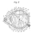
- Figures 2 and 3 show a module of a wristwatch with a pressure sensor used as a depth meter of the present invention.
- numeral 11 designates an oval-shaped support frame of LCD on the side of the dial 4, having a projection lla in the vicinity of the mark of nine o'clock.
- an oval-shaped circuit support frame 12 which is also adapted to support the module (or movement) provided on the side of a back cover 13 of the wristwatch.
- a main plate 14 which is provided with an opening 14a in which the LC cell 5 is located.
- a magnetic shield plate 15 having a shape in plan view substantially the same as that of the main plate 14 is located between the main plate 14 and the dial 4.
- the pushbuttons Sl, S2, and S3 have respective return springs 16, 17, and 18 which are held on the main plate 14, with the help of respective tubes 14b, 14c, and 14d and positioning pins 14e, 14f and 14g which are secured to the main plate 14.
- the associated return spring 16, 17, or 18 elastically deforms at its spring portion 16a, 17a, or 18a, so that its contact portion 16b, 17b, or 18b comes into contact with an associated side through hole conductor pattern 19a, 19b, or 19c of a printed circuit board 19 on the circuit support frame 12.
- the printed circuit board 19 has an arithmetic IC 19d, an amplifying IC 19e, and a hand driving IC 19f.
- a crystal oscillator 19g soldered thereto and other soldered elements (not shown) so as not to interfere with flat type batteries 20a, 20b, 20c which are provided on the side of the printed circuit board 19 adjacent to the back cover 13.
- the batteries 20a and 20b are electrically connected in series to each other through a battery connecting conductor spring 21, the printed circuit board 19, and a battery receiving conductor spring 22.
- the hands are driven by a stepping motor 23.
- the stepping motor 23 drives a train wheel block 24 which rotates a hour wheel 25, a center wheel (minute wheel) 26, and a second wheel 27.
- the hour hand 1, the minute hand 2, and the second hand 3 are mounted at the upper ends of the hour wheel 25, the center wheel 26, and the second wheel 27, respectively.
- the crown 7 is rigidly connected to a winding stem 28 which rotates the hands in order to adjust the time through a hand setting mechanism 29 per se known when the crown 7 is rotated after it is pulled.
- the pressure sensor 8 is electrically connected to the printed circuit board 19, which extends by the projection lla, by means of four coil springs 30.
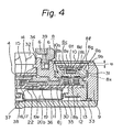
- the pressure sensor 8 comprises a ceramic package 8a in which a sensor chip block 8c is secured through an adhesive layer 8b of silicon resin which is adapted to absorb strain or deformation due to a difference in thermal expansion coefficients.
- the sensor chip block 8c is composed of a silicon chip 8d of a semiconductor pressure sensing element which has thereon four piezoresistances electrically interconnected in a bridge circuit (Fig. 5), and a heat-resistant glass 8e, such as Pyrex ® which has a thermal expansion coefficient very similar to that of the silicon chip 8d.
- the silicon chip 8d is etched at its undersurface in the vicinity of the center thereof.
- the silicon chip 8d and the heat-resistant glass 8e are connected to each other, for example, by electrostatic bonding, so that a vacuum space 8f is provided therebetween.
- the internal pressure (vacuum) in the shape 8f is kept constant, regardless of changes in temperature.
- the package 8a is filled with a gelled silicon resin 8g, which is a soft resin having a flowability in response to the change in pressure.
- the sensor chip block 8c is embedded in the silicon resin.
- On the silicon resin 8g is provided an upper layer 8h of silicon or rubber resin which is responsive to pressure change, so that external pressure, such as water pressure, can be reliably transmitted to the silicon chip 8d while ensuring protection against seawater or' the like.
- the change in pressure acting on the upper layer 8h of the pressure sensor 8 can be detected by the silicon chip 8d.
- the silicon chip 8d is electrically connected to electrodes 8j which are provided on the bottom face of the package 8a through conductor wires 8i extending between the chip 8d and conductor portions 81 of through holes 8k which are provided in the package 8a.
- the electrodes 8j i.e., the conductor pattern portions of the bottom face of the package 8a, are electrically connected to the printed circuit board through the coil springs 30.
- the pressure sensor 8 constructed above is press- fitted in the case 9 through a packing 31, so that the pressure which acts on the pressure sensor 8 can be received and absorbed by the case 9 through the packing 31 without the pressure acting on the elements of the module, such as the printed circuit board 19. This ensures high waterproofness and high pressure resistance of the wristwatch.
- the protective plate 10 is provided above the pressure sensor 8.
- the protective plate 10 is rigidly connected to and in a recess 9b provided in the case 9.
- the protective plate 10 is circular, as mentioned above, and has openings 10a (Fig. 1) which enable the water pressure to act on the upper layer 8h of the pressure sensor 8 therethrough.
- the openings 10a are provided as close as possible to the outer periphery of the protective plate, so that the openings 10a can be enlarged without increasing the width thereof.
- This arrangement of the openings 10a also contributes to prevention of the silicon chip 8d from being damaged, which otherwise would be damaged by insertion of something with a sharp end, such as a sharp pencil or ball pen. Those who wear the wristwatch may accidentally insert such a pencil or ball pen in the pressure sensor 8 through the openings 10a.
- the openings are located above the package 8a, so that even if the sharp end is inserted in the openings 10a, it is not accessible to the silicon chip through the upper layer 8h and through the silicon resin 8g.
- a gap d which is determined taking into consideration the easy discharge of foreign matter coming into the gap d through the openings 10a with the help of flowing water, so gap d is not clogged with such foregin matter, in consideration two of the construction and the thickness of the case 9, etc.
- the gap d is more than 200 ⁇ m. Otherwise, relatively small foreign matter which enters through the openings 10a tend to partially remain without being completely discharged, resulting in adhesion of foregin matter to the inner, i.e., bottom face of the protective plate 10 and to the upper, i.e., top face of the upper layer 8h after long time use.
- the gap d is less than 200 ⁇ m, it is difficult to pass water through the openings 10a to clean the gap d, i.e., to expel foreign matter out from the gap d.
- the gap is more than 1000 ⁇ m, although clogging can be eliminated, the size, in particular the thickness, of the case 9 of the watch is increased as a whole. This is clearly contrary to the need for minimizing or decreasing the thickness of the watch. Accordingly, the dimensions of the gap are very important. It has been experimentally found that the gap is preferably within the range of 200 to 1000 ⁇ m, as mentioned above, in order to satisfy both the requirements of prevention of clogging of the gap with foreign matter and easy cleaning of the gap by passing cleaning water and of decreased thickness.
- the gap d should be as large as possible in the range mentioned above in order to decrease the possibility of clogging with the foreign matter.
- Waterproof ring packings 33 and 34 are provided between the case 9 and the back cover 13 and between the case 9 and a glass 14.
- the magnetic shield 15, the main plate 14, the LCD support frame 11, the printed circuit board 19, the circuit support 12, the circuit support plate 35 are put one below another from the bottom face of the dial 4.
- the circuit support plate 35 is maintained, together with the case 9, the back cover 13, and the main plate 14, at a reference voltage (Vdd).
- the switch return springs 16 and 17, the amplifying IC 19e, the printed circuit board 19, the battery receiving spring 22, the flat type battery 20b, and the battery clamp plate 36 are provided, in that order, from the bottom surface of the main plate 14.
- the battery 20b is secured to the circuit support 12 through the battery clamp plate 36.
- the back cover 13 is provided, on the side facing the module, with a piezoelectric element 37 connected thereto.
- An insulation sheet 38 is connected to the piezoelectric element 37 for insulation from the batteries 20a, 20b, and 20c.
- the insulation sheet 38 also provides insulation between the battery 20a, which defines an electrode of an intermediate voltage at its surface adjacent to the back cover 13, and the back cover 13.
- the numeral 39 designates a register ring spring for preventing rotation of the register ring 6 in the clockwise direction.
- the register ring spring 39 is also adapted to ensure a moderate rotation of the register ring 6 in the counterclockwise direction.
- the protective plate 10 is partially overlapped by the register ring 6, which is used to measure the diving time, when viewed from the plan view, so that the projecting length of the projection 9a of the case 9 can be decreased.
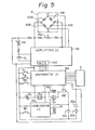
- FIG. 5 shows the basic circuit of the wristwatch shown in Fig. 1.
- the wristwatch has four IC chips, including the pressure sensor 8 (siliocn chip 8d).
- the arithmetic IC 19d and the amplifying IC 19e which includes an amplifying circuit and A/D converter 109, are supplied with 3V by two batteries 20a and 20b connected to each other in series.
- the hand driving IC 19f is supplied with 1.5V by the battery 20c.
- the pressure sensor 8 includes a bridge circuit consisting of four piezo resistances 108. The four terminals of the resistances are connected to the amplifying IC 19e.
- an offsetting trimmer resistance 19h for adjusting the output at a standard atmospheric pressure at a predetermined value.
- Resistances including a trimmer resistance 19i for adjusting the sensitivity of the amplifying IC 19e, and a condenser Cl are also provided.
- Sl, SII, and SIII designate switches which are made ON when the pushbuttons Sl, S2, and S3 are pushed, respectively.
- the LC cells 5 are connected to the arithmetic IC 19d.
- the numeral 19g is a crystal oscillator and 19j is a trimmer capacitor for adjusting the rate of the time.
- An alarm circuit is composed of an LC resonant circuit including a piezoelectric element 37 which forms a buzzer and a coil 19K which produces an increased voltage for driving the piezoelectric element 37, i.e., the buzzer, and of a transistor 19t which drives the resonant circuit.
- the alarm circuit is supplied with 1.5V by the battery 20c, in view of the balance of power consumption.
- the stepping motor 23 is connected to the hand driving IC 19f.
- the numeral 40 designates a reset switch which is made ON when the crown 7 is pulled to reset the hand driving IC 19f.
- FIG. 6 shows a block diagram of an embodiment of a pressure sensor which is used as a depth meter.
- the pressure sensor 8 in the form of a diaphragm type of semiconductor, issues analog signals to the amplifying IC 19e in response to the pressure on the pressure sensor 8.
- the output signals are converted to digital signals by the A/D converter 109 in the amplifying IC 19e.
- the arithmetic IC 19d has a time circuit 119a performing time functions, such as display of the time or date or issuing an alarm, as in an usual digital wristwatch, and a depth meter circuit 119b detecting the depth based on the measurement of the pressure by the pressure sensor 8.
- the time function or the depth function is selected by a function selection circuit 119d and is displayed by the LC cell 5.
- the function selection circuit 119d is actuated by a signal from a selection switch 119e.
- the time circuit 119a and the depth meter circuit 119b can be selectively displayed.
- the depth function is selected by the function selection circuit 119d
- the depth is displayed in the LC cell 5 in response to the depth function selection signal B from the selection switch 119e.
- the time function is selected, the time, date, etc. is displayed in the LC cell 5, in response to the time function selection signal C from the selection switch 119e.
- the selection switch 119e alternatively issues the signal B or C in response to a signal A which is input to the selection switch 119e every time the pushbuttons Sl, S2, or S3 are actuated for a long period (a few seconds).
- the signal B is also an initial pressure value setting signal.
- the signal B from the selection switch 119e is input into an abnormal value detection circuit 119f, whereupon the latter detects whether or not the pressure value to which the pressure measurement by the pressure sensor 8 is converted by the A/D converter 109 is abnormal. If the value is not abnormal, this value, which is called the initial pressure value, is stored in a memory 119g. On the contrary, if the detector 119f detects an abnormal value, the LC cell 5 displays it.
- the memory 119g opens a gate 131, so that the signal D which actuates the A/D converter 109 at a predetermined cycle passes through the gate 131.
- the signal D is fed from a clock signal generator 132 connected to the crystal oscillator 19g.
- the A/D converter 109 then converts the output from the pressure sensor 8 into a digital value which is input into depth conversion circuit 119c, in which a difference between the digital value and the above-mentioned initial pressure value is converted into a depth value which is then displayed in the LC cell 5.
- the detection of an abnormal value is effected in the detection circuit 119f on the basis of the possible maximum variation in the atmospheric pressure for a long period and a total variation of input-output characteristics in the pressure sensor and the A/D converter due to aging. Namely, the detection circuit 119f detects abnormality due to trouble or failure of the system.
- the numeral 119h designates a water detection circuit which detects whether or not the depth detected by the depth converter circuit 119c is positive.
- the selection switch 119e When the depth value is positive, which means that the pressure sensor 8 is in the water, the selection switch 119e does not operate even if the signal A is input into the selection switch 119e by the actuation of the pushbutton Sl, S2, or S3. That is, the time function cannot be selected in the water.
- the selection switch 119e which has therein means for prohibiting the issuance of output from the selection switch when the depth value is positive.
- Such a prohibiting means (circuit) is per se known. Accordingly, no signal B is issued, so that there is no possibility of reset of the initial pressure value by mistake by a diver.
- the diver selects the depth functions before he dives, so that the variation of the atmospheric pressure, variation of the input-output characteristics due to aging of the pressure sensor and A/D converter, etc. can be automatically excluded and a correct or precise depth can be displayed in the water.
- FIG. 7 shows a block diagram of a second embodiment of the depth meter according to the present invention.
- the depth meter circuit 119b has a diving information circuit 119i besides the depth conversion circuit 119c.
- the diving information circuit 119i provides the "diving information function", i.e., buzzing when an actual depth is deeper than a preset depth of diving and other functions besides the depth indication.
- the signal B is issued from the selection switch 119e in response to the signal A, and the time is displayed in the LC cell 5.
- the signal B is also an initial pressure signal, as mentioned before. If the abnormal value detection circuit 119f detects that the initial pressure value is normal, it is stored in the memory 119g.
- a switch input control circuit 119j is activated to pass a depth measurement starting signal E from the pushbutton therethrough in order to open the gate 131.
- the AID converter 109 is actuated to send the converted pressure value to the depth conversion circuit 119c, in which the difference between the converted pressure value-and the initial pressure value is converted to a depth and the depth is displayed in the LC cell 5.
- the operation of the embodiment is similar to that of Fig. 6 except for the diving information circuit.
- the diving information function is accessible under atmospheric pressure.
- the setting of the initial pressure value can be automatically effected by access also under atmospheric pressure, contributing to safe diving.
- the depth conversion circuit is not activated until the switch input control circuit ll g j receives the depth measurement starting signal, the power consumption can be decreased.
- the initial pressure value is stored in the memory when the depth function is selected from the time function, the same effect can be also expected in any state other than depth function, including the state that nothing is displayed, in place of the time function.
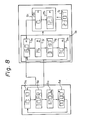
- FIG. 8 is a block diagram of the display of the LC cell 5.
- Fig. 8 are shown different modes 5a to 5j of display in the time function and diving information, which will be described later.
- the display changes from the mode 5a to the mode 5b and then changes to the mode 5e, which designates the memorized deepest depth, which is one of the depth meter functions.
- the "memorized deepest depth” referred to means the deepest depth memorized in the preceding diving once before.
- the display changes from the mode 5e to the mode 5f in which a diving depth alarm in which a buzzer sounds when the depth exceeds a preset depth is displayed, then to the mode 5g in which a recorded diving time is displayed, and then to the-mode 5h in which a diving time alarm is displayed.
- the diving time alarm sounds.
- the display further returns to the mode 5e. From Fig. 8, it can be found that the deepest depth of diving was 16.0 m, the diving time was 37 minutes and 30 seconds, and the buzzer sounded at the depth of 15 m and at the diving time of 30 minutes.
- the set values of the alarm time and depth can be modified by the pushbutton S3.
- the display changes to the depth measurement display 5i from the diving information 5K.
- the display changes from the mode 15i in which 0 m is displayed to the mode 25i in which the depth of 12.3 m is displayed in response to the water pressure in the sea.
- the display does not change even when the pushbutton Sl is pushed in the water.
- the diving time mode 5j is accessible even during diving.
- the change of the function from the depth function to the time function is effected by pushing, for example, the pushbutton S2 for a few seconds in the modes 5e to 5h, so that after the mode changes from the deepest depth mode 5e to the diving depth alarm mode 5f, the mode changes to the time mode 5a, just as with the change of the mode from the time function display to the depth function display.
- additional information such as descent rate and/or ascent rate, can be included in the diving information, so that if the actual diving or surfacing speed is greater than a preset diving or surfacing speed, the buzzer sounds.
- the display of the time mode successives changes from 5a to 5d.
- the mode 5a is the time display
- the mode 5b is the date display
- the mode 5c is the alarm time display, in which the buzzer sounds upon the preset alarm time
- the mode 5d is the stopwatch display.
- the pushbutton S2 is actuated, the modes 5a to 5d repeat.
- the time display shown in Fig. 8 when the pushbuttons Sl and S3 are actuated, the second of time appears. Correction of the time, date, and alarm time, setting and release of the alarm, starting and stopping of the stopwatch function and reset of the stopwatch, can be performed as in a usual digital wristwatch.
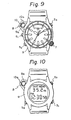
- Figure 9 shows a different arrangement of the pressure sensor 8, in which the latter is located in the vicinity of the mark representing 10 o'clock. Namely, the push button Sl and the pressure sensor 8 shown in Fig. 1 are switched in their positions.
- Figure 10 shows a different embodiment of the present invention applied to a digital wristwatch.
- the wristwatch has only digital diaplay and does not have analog display elements, such as hands, 12 marks representing hours, etc. Since there is no crown for moving the hands in a digital wristwatch, the pressure sensor 8 of the present invention can be located for example, at the position of the pushbutton Sl of the wristwatch shown in Fig. 1, i.e., in the northwest direction in plan view. Furthermore, in the arrangement illustrated in Fig. 9, the crown 7 in Fig. 1 is replaced by the pushbutton Sl.
- the various functions of the wristwatch shown in Fig. 9 are the same as those of the wristwatch shown in Fig. 1, mentioned above.
- a pressure sensor is provided, for example, in a projection provided on the wristwatch case adjacent to the nine o'clock mark. Accordingly, the pressure sensor does not decrease the visibility of the dial.
- the arrangement of the pressure sensor is advantageous, because the pressure sensor does not interfere with the back of the diver's hand when he wears the wristwatch on his left hand.
- the pressure sensor can be advantageously provided on the wristwatch case adjacent to the three o'clock mark. The provision of the pressure sensor does not have any adverse influence on the conventional functions necessary for a digital or analog wristwatch.
- the small gap between the protective plate 10 and the upper layer 8h of the pressure sensor 8 helps realize a thin wristwatch.
- the pressure sensor of the present invention can precisely detect the water pressure and can be protected from entry of foreign matter such as dust or sand. Even if foreign matter enters the pressure sensor, it can be easily removed therefrom by flushing with water.
- the pressure sensor 8 has a sufficient pressure resistance and a water-sealed construction from the module of the wristwatch.
- the actual pressure is a sum of the atmospheric pressure acting on the water surface and the weight of the water depending on the depth.
- the water depth h is given by the following formula:
- the density of sea water is slightly different from that of water. Accordingly, when the wristwatch of the present invention is used as a depth meter for sea diving, the density of the sea water is input and used in the arithmetic process of the detection.
- the atmospheric pressure is not always constant and can vary. According to the present invention, since the initial pressure preset is effected under the atmospheric pressure, namely before diving, the actual atmospheric pressure is introduced, resulting in precise detection of the depth.
- the twelve o'clock mark is shifted away from the circle along which the other marks are arranged, the twelve o'clock mark is visible despite the LCD window.
- the location of the LCD window is not limited to the illustrated embodiment. It can be also located on the six o'clock, three o'clock, or nine o'clock marks. In such an alternative, the. associated marks can be shifted slightly in the radial inward direction in comparison with the remaining marks.
- the wristwatch is used as a depth meter, the depth can be clearly displayed in response to the water pressure without being influenced by the change in the atmospheric pressure and the change of the input-output characteristics in the pressure sensor and the IC chips in the electronic circuits provided in the wristwatch.
- Various diving information can be included in the diving function. For example, a diving duration can be also recorded and displayed. Since the depth and various diving information can be displayed merely by actuating the associated pushbutton, the wristwatch is very advantageous for safety under the special environment of the sea.
Landscapes
- Physics & Mathematics (AREA)
- General Physics & Mathematics (AREA)
- Engineering & Computer Science (AREA)
- Radar, Positioning & Navigation (AREA)
- Remote Sensing (AREA)
- Mechanical Engineering (AREA)
- Ocean & Marine Engineering (AREA)
- Electric Clocks (AREA)
Applications Claiming Priority (6)
| Application Number | Priority Date | Filing Date | Title |
|---|---|---|---|
| JP3910785U JPS61154585U (de) | 1985-03-19 | 1985-03-19 | |
| JP39107/85U | 1985-03-19 | ||
| JP21332285 | 1985-09-26 | ||
| JP60213323A JPH0664161B2 (ja) | 1985-09-26 | 1985-09-26 | 水深計付電子時計 |
| JP213323/85 | 1985-09-26 | ||
| JP213322/85 | 1985-09-26 |
Publications (3)
| Publication Number | Publication Date |
|---|---|
| EP0195636A2 true EP0195636A2 (de) | 1986-09-24 |
| EP0195636A3 EP0195636A3 (en) | 1989-01-04 |
| EP0195636B1 EP0195636B1 (de) | 1991-07-10 |
Family
ID=27290038
Family Applications (1)
| Application Number | Title | Priority Date | Filing Date |
|---|---|---|---|
| EP86301936A Expired - Lifetime EP0195636B1 (de) | 1985-03-19 | 1986-03-17 | Armbanduhr mit Druckmessfühler |
Country Status (4)
| Country | Link |
|---|---|
| US (1) | US4783772A (de) |
| EP (1) | EP0195636B1 (de) |
| AU (1) | AU577452B2 (de) |
| DE (1) | DE3680127D1 (de) |
Cited By (11)
| Publication number | Priority date | Publication date | Assignee | Title |
|---|---|---|---|---|
| EP0308522A1 (de) * | 1987-09-19 | 1989-03-29 | Vertical Instruments, Inc. | Halbleiterhöhenmesser mit richtungsabhängiger Integration |
| EP0439255A1 (de) * | 1990-01-10 | 1991-07-31 | Seiko Epson Corporation | Elektronisches Gerät mit Tiefenanzeiger |
| DE4036994A1 (de) * | 1990-11-20 | 1992-05-21 | Divetronic Ag | Anzeigevorrichtung als elektrische/elektronische instrumente, insbesondere tauchcomputer |
| EP0388138B1 (de) * | 1989-03-15 | 1994-06-08 | Seiko Instruments Inc. | Uhr |
| EP0640896A1 (de) * | 1993-07-01 | 1995-03-01 | Seiko Epson Corporation | Elektronische Uhr |
| WO2004107826A2 (en) | 2003-05-29 | 2004-12-09 | Timex Group B.V. | Multi functional timepiece module with application specific printed circuit boards |
| US7159469B2 (en) * | 2003-12-17 | 2007-01-09 | Eta Sa Manufacture Horlogère Suisse | Portable electronic appliance including a pressure sensor |
| EP1544696A3 (de) * | 2003-12-17 | 2009-06-24 | ETA SA Manufacture Horlogère Suisse | Tragbares elektronisches Gerät, das mit einem Drucksensor ausgerüstet ist |
| US7733794B2 (en) | 2005-06-17 | 2010-06-08 | Alcatel Lucent | Performance monitoring of frame transmission in data network OAM protocols |
| CN1904772B (zh) * | 2005-07-29 | 2011-04-27 | Eta瑞士钟表制造股份有限公司 | 包含冗余瞬时深度显示的电子潜水手表 |
| ITGE20130094A1 (it) * | 2013-09-25 | 2015-03-26 | Cressi Sub Spa | Computer da polso per subacquei |
Families Citing this family (83)
| Publication number | Priority date | Publication date | Assignee | Title |
|---|---|---|---|---|
| GB2202950B (en) * | 1987-03-17 | 1990-09-12 | Citizen Watch Co Ltd | Sensor signal processor |
| DE8711105U1 (de) * | 1987-08-14 | 1987-11-26 | Siemens AG, 1000 Berlin und 8000 München | Leiterplatte für die Elektronik |
| USD315512S (en) | 1988-04-22 | 1991-03-19 | Timex Corporation | Timing watch |
| DE68909842T2 (de) * | 1988-06-07 | 1994-04-14 | Citizen Watch Co Ltd | Einrichtung zur Messung von Höhe und barometrischem Druck. |
| US5224059A (en) * | 1988-06-07 | 1993-06-29 | Citizen Watch Co., Ltd. | Device for measuring altitude and barometric pressure |
| US5189646A (en) * | 1988-07-20 | 1993-02-23 | Seiko Epson Corporation | Small-sized electronic device with depth gauge |
| US5031160A (en) * | 1988-07-20 | 1991-07-09 | Seiko Epson Corporation | Small-sized electronic device with depth gauge |
| USD316983S (en) | 1988-08-05 | 1991-05-21 | Timex Corporation | Combined analog and digital wristwatch |
| USD316676S (en) | 1988-08-26 | 1991-05-07 | Timex Corporation | Wrist watch |
| US5148376A (en) * | 1989-07-12 | 1992-09-15 | Casio Computer Co., Ltd. | Pressure instrument with depth/altitude and time display |
| US5357488A (en) * | 1990-07-03 | 1994-10-18 | Citizen Watch Co., Ltd. | Watch having a sensor |
| USD333100S (en) | 1990-08-30 | 1993-02-09 | Casio Computer Co., Ltd. | Wrist watch |
| USD343584S (en) | 1990-09-05 | 1994-01-25 | Sunburst Products, Inc. dba Free Style U.S.A. | Watch |
| US5251190A (en) * | 1991-02-22 | 1993-10-05 | Citizen Watch Co., Ltd. | Electronic timepiece having functional hands |
| US6490230B1 (en) | 1991-04-16 | 2002-12-03 | Citizen Watch Co., Ltd. | Electronic watch with meter function and display means |
| JPH05240969A (ja) * | 1992-02-26 | 1993-09-21 | Casio Comput Co Ltd | センサ機能を有した電子機器 |
| US5253532A (en) * | 1992-03-09 | 1993-10-19 | Timex Corporation | Temperature compensated pressure transducer with digital output for low voltage power supply |
| DE69415305T2 (de) * | 1993-03-12 | 1999-04-29 | Citizen Watch Co., Ltd., Tokio/Tokyo | Mit funktion zur messung der wassertiefe ausgerüstetes elektronisches gerät |
| US5617848A (en) * | 1993-11-17 | 1997-04-08 | Cochran; Michael J. | Advanced dive computer that calculates and displays the user's breathing parameter and water salinity |
| ES2149316T3 (es) * | 1994-04-14 | 2000-11-01 | Citizen Watch Co Ltd | Reloj de pulsera dotado de un sensor. |
| USD363883S (en) | 1995-03-07 | 1995-11-07 | Citizen Watch Co., Ltd. | Wrist watch |
| USD392572S (en) | 1997-02-06 | 1998-03-24 | Larsen & Brusgaard Aps | Automatic timer and altimeter |
| ATE337575T1 (de) * | 1998-06-22 | 2006-09-15 | Seiko Epson Corp | Struktur zur montage eines fühlers, elektronische vorrichtung sowie uhr mit einersolchen struktur |
| JP2000138607A (ja) * | 1998-08-27 | 2000-05-16 | Casio Comput Co Ltd | リスト装置および電子機器 |
| DE69940644D1 (de) * | 1998-12-23 | 2009-05-07 | Asulab Sa | Uhr mit barometer oder höhenanzeige und verfahren zu ihrer herstellung |
| DE60040590D1 (de) * | 1999-09-08 | 2008-12-04 | Seiko Epson Corp | Informationsverarbeitungsvorrichtung für taucher |
| WO2002014959A1 (fr) * | 2000-08-15 | 2002-02-21 | Citizen Watch Co., Ltd. | Système d'horlogerie électronique et technique de commande de celui-ci |
| JP4021218B2 (ja) * | 2001-04-24 | 2007-12-12 | セイコーエプソン株式会社 | 電子時計 |
| MD20020099A (ro) * | 2002-03-20 | 2003-11-30 | Руслан ВРЕМЯ | Deşteptător cu traductor |
| JP3536852B2 (ja) * | 2002-03-27 | 2004-06-14 | セイコーエプソン株式会社 | 電子時計 |
| US6791903B2 (en) * | 2002-09-04 | 2004-09-14 | Asulab S.A. | Electronic diving watch with analog display |
| US6842402B2 (en) * | 2002-09-04 | 2005-01-11 | Asulab S.A. | Electronic diving watch with analog display |
| JP4361384B2 (ja) * | 2004-01-29 | 2009-11-11 | セイコーインスツル株式会社 | 報音機能付携帯型電子装置 |
| EP1571506A1 (de) | 2004-03-03 | 2005-09-07 | ETA SA Manufacture Horlogère Suisse | Elektronisches Gerät mit analogen Anzeige der Geschichte mindestens einer physikalischen Grösse, die von einem Sensor gemessen wird |
| DE602004012729T2 (de) * | 2004-07-13 | 2009-04-16 | Eta Sa Manufacture Horlogère Suisse | Verfahren zur Detektion des Tauchbeginnes für einen Tauchcomputer |
| US7256702B2 (en) * | 2004-08-18 | 2007-08-14 | Michael S. Isaacs | Gas supply pressure alarm device |
| EP1672443B1 (de) | 2004-12-17 | 2010-08-18 | ETA SA Manufacture Horlogère Suisse | Uhr mit einem Drucksensor |
| JP5103169B2 (ja) * | 2005-03-25 | 2012-12-19 | シチズンホールディングス株式会社 | 電子機器および表示制御方法 |
| FI119262B (fi) * | 2005-11-30 | 2008-09-15 | Suunto Oy | Sovitelma paineen mittauksen järjestämiseksi ranneinstrumenttiin |
| US7441460B2 (en) * | 2006-11-07 | 2008-10-28 | Precision Medical, Inc. | Vacuum regulator with two gauges |
| JP5279661B2 (ja) * | 2009-08-28 | 2013-09-04 | セイコーインスツル株式会社 | 携帯時計 |
| JP5405945B2 (ja) * | 2009-08-28 | 2014-02-05 | セイコーインスツル株式会社 | 携帯時計 |
| JP5285547B2 (ja) * | 2009-08-28 | 2013-09-11 | セイコーインスツル株式会社 | 携帯時計 |
| JP2011191213A (ja) * | 2010-03-15 | 2011-09-29 | Seiko Instruments Inc | センサ付電子機器 |
| JP4775749B1 (ja) * | 2010-10-02 | 2011-09-21 | 日本テクノ株式会社 | 時計 |
| JP6022715B2 (ja) * | 2013-01-18 | 2016-11-09 | ウーテーアー・エス・アー・マニファクチュール・オロロジェール・スイス | 時計センサ用の支持要素 |
| US9753436B2 (en) | 2013-06-11 | 2017-09-05 | Apple Inc. | Rotary input mechanism for an electronic device |
| JP6345782B2 (ja) | 2013-08-09 | 2018-06-20 | アップル インコーポレイテッド | 電子デバイス用のタクタイルスイッチ |
| WO2015122885A1 (en) | 2014-02-12 | 2015-08-20 | Bodhi Technology Ventures Llc | Rejection of false turns of rotary inputs for electronic devices |
| US9367100B2 (en) | 2014-07-07 | 2016-06-14 | Apple Inc. | Electronic devices with submersion detection circuitry |
| US10190891B1 (en) | 2014-07-16 | 2019-01-29 | Apple Inc. | Optical encoder for detecting rotational and axial movement |
| CN205121417U (zh) | 2014-09-02 | 2016-03-30 | 苹果公司 | 可穿戴电子设备 |
| US10145711B2 (en) | 2015-03-05 | 2018-12-04 | Apple Inc. | Optical encoder with direction-dependent optical properties having an optically anisotropic region to produce a first and a second light distribution |
| WO2016144919A1 (en) | 2015-03-08 | 2016-09-15 | Apple Inc. | Compressible seal for rotatable and translatable input mechanisms |
| US10018966B2 (en) | 2015-04-24 | 2018-07-10 | Apple Inc. | Cover member for an input mechanism of an electronic device |
| EP3136071B1 (de) * | 2015-08-25 | 2018-03-28 | The Swatch Group Research and Development Ltd. | Kalibriervorrichtung und -verfahren einer höhenmessvorrichtung |
| US10401167B2 (en) * | 2015-09-17 | 2019-09-03 | Apple Inc. | Wearable ambient pressure gauge |
| EP3168694B1 (de) * | 2015-11-11 | 2019-01-02 | Blancpain SA. | Anzeigemechanismus der aufsteigegeschwindigkeit, und mit einem solchen mechanismus ausgestattete taucheruhr |
| EP3182221A1 (de) * | 2015-12-15 | 2017-06-21 | Omega SA | Uhrenarmband |
| US9891651B2 (en) | 2016-02-27 | 2018-02-13 | Apple Inc. | Rotatable input mechanism having adjustable output |
| US10551798B1 (en) | 2016-05-17 | 2020-02-04 | Apple Inc. | Rotatable crown for an electronic device |
| US10061399B2 (en) | 2016-07-15 | 2018-08-28 | Apple Inc. | Capacitive gap sensor ring for an input device |
| US10019097B2 (en) | 2016-07-25 | 2018-07-10 | Apple Inc. | Force-detecting input structure |
| US10664074B2 (en) | 2017-06-19 | 2020-05-26 | Apple Inc. | Contact-sensitive crown for an electronic watch |
| US10962935B1 (en) | 2017-07-18 | 2021-03-30 | Apple Inc. | Tri-axis force sensor |
| JP6836193B2 (ja) * | 2017-09-27 | 2021-02-24 | カシオ計算機株式会社 | 計測装置、制御方法及びプログラム |
| US11360440B2 (en) | 2018-06-25 | 2022-06-14 | Apple Inc. | Crown for an electronic watch |
| US11561515B2 (en) | 2018-08-02 | 2023-01-24 | Apple Inc. | Crown for an electronic watch |
| US12259690B2 (en) | 2018-08-24 | 2025-03-25 | Apple Inc. | Watch crown having a conductive surface |
| US11181863B2 (en) | 2018-08-24 | 2021-11-23 | Apple Inc. | Conductive cap for watch crown |
| CN209560398U (zh) | 2018-08-24 | 2019-10-29 | 苹果公司 | 电子表 |
| US11194298B2 (en) | 2018-08-30 | 2021-12-07 | Apple Inc. | Crown assembly for an electronic watch |
| CN209625187U (zh) | 2018-08-30 | 2019-11-12 | 苹果公司 | 电子手表和电子设备 |
| US11194299B1 (en) | 2019-02-12 | 2021-12-07 | Apple Inc. | Variable frictional feedback device for a digital crown of an electronic watch |
| US20230185245A1 (en) * | 2019-08-01 | 2023-06-15 | Vladimir P. Kulikov | Time system clock face and method 364 degree for determining the time of the day |
| US10921203B1 (en) * | 2019-11-20 | 2021-02-16 | Harris Global Communications, Inc. | Communication system with immersion counter |
| US11550268B2 (en) | 2020-06-02 | 2023-01-10 | Apple Inc. | Switch module for electronic crown assembly |
| US11983035B2 (en) | 2020-06-11 | 2024-05-14 | Apple Inc. | Electronic device |
| US12092996B2 (en) | 2021-07-16 | 2024-09-17 | Apple Inc. | Laser-based rotation sensor for a crown of an electronic watch |
| US12189347B2 (en) | 2022-06-14 | 2025-01-07 | Apple Inc. | Rotation sensor for a crown of an electronic watch |
| JP7643425B2 (ja) * | 2022-09-26 | 2025-03-11 | カシオ計算機株式会社 | センサ装置および時計 |
| US12596334B2 (en) | 2023-02-07 | 2026-04-07 | Apple Inc. | Crown for an electronic watch |
| CN119148497B (zh) * | 2024-11-14 | 2025-01-07 | 深圳市琦沃科技发展有限公司 | 一种可监测水压的智能手表 |
Family Cites Families (18)
| Publication number | Priority date | Publication date | Assignee | Title |
|---|---|---|---|---|
| US3031591A (en) * | 1959-05-27 | 1962-04-24 | Gen Electric | Pressure measuring gage |
| US3198013A (en) * | 1961-10-05 | 1965-08-03 | Pechiney | Pressure gage |
| CH489048A (fr) * | 1967-04-14 | 1969-12-31 | Manuf Des Montres Doxa S A | Montre de plongeur |
| AU424116B2 (en) * | 1968-04-02 | 1972-05-12 | Fredrick James Masters | Combination watch depth meter |
| DE7518826U (de) * | 1975-06-12 | 1975-11-27 | Stusak J | Kompaktgehaeuse fuer uhr hoehenmesser barometerskala und marschkompass |
| US4107995A (en) * | 1976-09-13 | 1978-08-22 | James Raymond Ligman | Recorder for decompression data |
| US4257115A (en) * | 1977-02-12 | 1981-03-17 | Citizen Watch Co., Ltd. | Switch structure for electronic timepiece |
| DE2711343A1 (de) * | 1977-03-16 | 1978-09-21 | Heinz Meitinger | Uhr mit zusatzfunktion |
| US4109140A (en) * | 1977-04-19 | 1978-08-22 | Richard Henry Etra | Diver's control and indication apparatus |
| JPS53144776A (en) * | 1977-05-24 | 1978-12-16 | Seiko Epson Corp | Crystal wristwatch |
| CH616551B (fr) * | 1978-04-26 | Ebauches Electroniques Sa | Piece d'horlogerie electronique avec indicateur barometrique. | |
| JPS5522125A (en) * | 1978-08-04 | 1980-02-16 | Hitachi Ltd | Pressure sensor |
| US4188825A (en) * | 1978-12-14 | 1980-02-19 | Farrar James G | Monitor for divers to avoid decompression |
| US4352168A (en) * | 1980-04-14 | 1982-09-28 | Anderson Robert D | Diver's bottom timer/depth gauge or the like and direct digital input and tracking system therefor |
| JPS57169644A (en) * | 1981-04-14 | 1982-10-19 | Nippon Denso Co Ltd | Semiconductor type pressure sensor |
| IT8153632U1 (it) * | 1981-09-25 | 1983-03-25 | Allemano Emilio | Strumento subacqueo per la lettura combinata di tempi e profondita' di immersione e tempi di decompressione. |
| US4533256A (en) * | 1983-12-29 | 1985-08-06 | Divers Supply Co., Inc. | Dive timer |
| US4611923A (en) * | 1984-11-30 | 1986-09-16 | Citizen Watch Co., Ltd. | Electronic timepiece with a depth gauge |
-
1986
- 1986-03-17 DE DE8686301936T patent/DE3680127D1/de not_active Expired - Lifetime
- 1986-03-17 EP EP86301936A patent/EP0195636B1/de not_active Expired - Lifetime
- 1986-03-18 AU AU54822/86A patent/AU577452B2/en not_active Expired
-
1988
- 1988-02-29 US US07/165,361 patent/US4783772A/en not_active Expired - Lifetime
Cited By (16)
| Publication number | Priority date | Publication date | Assignee | Title |
|---|---|---|---|---|
| EP0308522A1 (de) * | 1987-09-19 | 1989-03-29 | Vertical Instruments, Inc. | Halbleiterhöhenmesser mit richtungsabhängiger Integration |
| EP0388138B1 (de) * | 1989-03-15 | 1994-06-08 | Seiko Instruments Inc. | Uhr |
| EP0439255A1 (de) * | 1990-01-10 | 1991-07-31 | Seiko Epson Corporation | Elektronisches Gerät mit Tiefenanzeiger |
| DE4036994A1 (de) * | 1990-11-20 | 1992-05-21 | Divetronic Ag | Anzeigevorrichtung als elektrische/elektronische instrumente, insbesondere tauchcomputer |
| EP0640896A1 (de) * | 1993-07-01 | 1995-03-01 | Seiko Epson Corporation | Elektronische Uhr |
| EP0769734A3 (de) * | 1993-07-01 | 1997-05-21 | Seiko Epson Corporation | Elektronische Uhr |
| US5802016A (en) * | 1993-07-01 | 1998-09-01 | Seiko Epson Corporation | Electronic watch |
| US7406003B2 (en) | 2003-05-29 | 2008-07-29 | Timex Group B.V. | Multifunctional timepiece module with application specific printed circuit boards |
| WO2004107826A2 (en) | 2003-05-29 | 2004-12-09 | Timex Group B.V. | Multi functional timepiece module with application specific printed circuit boards |
| EP1634127A4 (de) * | 2003-05-29 | 2008-02-20 | Timex Group Bv | Multifunktions-uhrmodul mit anwendungsspezifischen leiterplatten |
| US7159469B2 (en) * | 2003-12-17 | 2007-01-09 | Eta Sa Manufacture Horlogère Suisse | Portable electronic appliance including a pressure sensor |
| EP1544696A3 (de) * | 2003-12-17 | 2009-06-24 | ETA SA Manufacture Horlogère Suisse | Tragbares elektronisches Gerät, das mit einem Drucksensor ausgerüstet ist |
| US7733794B2 (en) | 2005-06-17 | 2010-06-08 | Alcatel Lucent | Performance monitoring of frame transmission in data network OAM protocols |
| CN1904772B (zh) * | 2005-07-29 | 2011-04-27 | Eta瑞士钟表制造股份有限公司 | 包含冗余瞬时深度显示的电子潜水手表 |
| ITGE20130094A1 (it) * | 2013-09-25 | 2015-03-26 | Cressi Sub Spa | Computer da polso per subacquei |
| EP2853960A3 (de) * | 2013-09-25 | 2016-07-13 | Cressi-Sub S.p.A. | Armbandrechner für Taucher |
Also Published As
| Publication number | Publication date |
|---|---|
| EP0195636B1 (de) | 1991-07-10 |
| AU577452B2 (en) | 1988-09-22 |
| US4783772A (en) | 1988-11-08 |
| DE3680127D1 (de) | 1991-08-14 |
| EP0195636A3 (en) | 1989-01-04 |
| AU5482286A (en) | 1986-09-25 |
Similar Documents
| Publication | Publication Date | Title |
|---|---|---|
| EP0195636B1 (de) | Armbanduhr mit Druckmessfühler | |
| US5500835A (en) | Weather forecasting watch | |
| EP0640896B1 (de) | Elektronische Uhr | |
| TWI324712B (en) | Electronic diving watch with analog display | |
| US4694694A (en) | Solid state accumulating altimeter | |
| US7269100B2 (en) | Electronic dive watch including a redundant instantaneous depth display | |
| US7242639B2 (en) | Altimeter watch | |
| JP3308080B2 (ja) | 温度表示装置を備えた時計 | |
| HK121997A (en) | Electronic timepiece having functional hands | |
| JP3329817B2 (ja) | 水深計測機能付電子機器 | |
| JPWO1994020886A1 (ja) | 水深計測機能付電子機器 | |
| RU2006144097A (ru) | Механизм электронного инструмента/барометра | |
| CN112051722B (zh) | 电子钟表的控制方法以及电子钟表 | |
| US6958954B2 (en) | Device indicating the state of batteries designed to equip a watch | |
| US11921465B2 (en) | Electronic watch | |
| JP2586642Y2 (ja) | 機能針付電子時計 | |
| JP3742160B2 (ja) | 水深計付き電子腕時計 | |
| EP0308522A1 (de) | Halbleiterhöhenmesser mit richtungsabhängiger Integration | |
| JP2603262Y2 (ja) | 指針式圧力計付腕時計 | |
| JP3502152B2 (ja) | 機能針付電子時計 | |
| JPH0650347B2 (ja) | 圧力センサ付電子機器 | |
| JPH0933669A (ja) | センサ付きアナログ−デジタル表示電子腕時計 | |
| AU2007101144A4 (en) | Timing Device | |
| JP3810549B2 (ja) | 電子時計の構造 | |
| JPH04315090A (ja) | 指針式機能時計 |
Legal Events
| Date | Code | Title | Description |
|---|---|---|---|
| PUAI | Public reference made under article 153(3) epc to a published international application that has entered the european phase |
Free format text: ORIGINAL CODE: 0009012 |
|
| AK | Designated contracting states |
Kind code of ref document: A2 Designated state(s): DE FR GB IT |
|
| PUAL | Search report despatched |
Free format text: ORIGINAL CODE: 0009013 |
|
| AK | Designated contracting states |
Kind code of ref document: A3 Designated state(s): DE FR GB IT |
|
| 17P | Request for examination filed |
Effective date: 19890403 |
|
| 17Q | First examination report despatched |
Effective date: 19890727 |
|
| GRAA | (expected) grant |
Free format text: ORIGINAL CODE: 0009210 |
|
| AK | Designated contracting states |
Kind code of ref document: B1 Designated state(s): DE FR GB IT |
|
| ITF | It: translation for a ep patent filed | ||
| REF | Corresponds to: |
Ref document number: 3680127 Country of ref document: DE Date of ref document: 19910814 |
|
| ET | Fr: translation filed | ||
| PLBE | No opposition filed within time limit |
Free format text: ORIGINAL CODE: 0009261 |
|
| STAA | Information on the status of an ep patent application or granted ep patent |
Free format text: STATUS: NO OPPOSITION FILED WITHIN TIME LIMIT |
|
| 26N | No opposition filed | ||
| REG | Reference to a national code |
Ref country code: GB Ref legal event code: IF02 |
|
| PGFP | Annual fee paid to national office [announced via postgrant information from national office to epo] |
Ref country code: FR Payment date: 20050308 Year of fee payment: 20 |
|
| PGFP | Annual fee paid to national office [announced via postgrant information from national office to epo] |
Ref country code: DE Payment date: 20050310 Year of fee payment: 20 |
|
| PGFP | Annual fee paid to national office [announced via postgrant information from national office to epo] |
Ref country code: GB Payment date: 20050316 Year of fee payment: 20 |
|
| PGFP | Annual fee paid to national office [announced via postgrant information from national office to epo] |
Ref country code: IT Payment date: 20050330 Year of fee payment: 20 |
|
| PG25 | Lapsed in a contracting state [announced via postgrant information from national office to epo] |
Ref country code: GB Free format text: LAPSE BECAUSE OF EXPIRATION OF PROTECTION Effective date: 20060316 |
|
| REG | Reference to a national code |
Ref country code: GB Ref legal event code: PE20 |