EP0195645A1 - Konstruktion für Zylinderverschlussgewehr - Google Patents
Konstruktion für Zylinderverschlussgewehr Download PDFInfo
- Publication number
- EP0195645A1 EP0195645A1 EP86301952A EP86301952A EP0195645A1 EP 0195645 A1 EP0195645 A1 EP 0195645A1 EP 86301952 A EP86301952 A EP 86301952A EP 86301952 A EP86301952 A EP 86301952A EP 0195645 A1 EP0195645 A1 EP 0195645A1
- Authority
- EP
- European Patent Office
- Prior art keywords
- receiver
- plates
- cartridge
- rifle
- ring
- Prior art date
- Legal status (The legal status is an assumption and is not a legal conclusion. Google has not performed a legal analysis and makes no representation as to the accuracy of the status listed.)
- Granted
Links
- 230000009471 action Effects 0.000 title claims abstract description 38
- 238000000034 method Methods 0.000 claims abstract description 14
- 230000001965 increasing effect Effects 0.000 claims abstract description 12
- 230000008878 coupling Effects 0.000 claims description 3
- 238000010168 coupling process Methods 0.000 claims description 3
- 238000005859 coupling reaction Methods 0.000 claims description 3
- 230000000284 resting effect Effects 0.000 claims description 3
- 238000007688 edging Methods 0.000 claims 1
- 239000004411 aluminium Substances 0.000 description 4
- 229910052782 aluminium Inorganic materials 0.000 description 4
- XAGFODPZIPBFFR-UHFFFAOYSA-N aluminium Chemical compound [Al] XAGFODPZIPBFFR-UHFFFAOYSA-N 0.000 description 4
- 229910000831 Steel Inorganic materials 0.000 description 3
- 210000000245 forearm Anatomy 0.000 description 3
- 238000004519 manufacturing process Methods 0.000 description 3
- 239000010959 steel Substances 0.000 description 3
- 229910001369 Brass Inorganic materials 0.000 description 2
- 239000010951 brass Substances 0.000 description 2
- 238000010276 construction Methods 0.000 description 2
- 238000010304 firing Methods 0.000 description 2
- 239000000463 material Substances 0.000 description 2
- 239000007787 solid Substances 0.000 description 2
- 238000005303 weighing Methods 0.000 description 2
- 241000755266 Kathetostoma giganteum Species 0.000 description 1
- 241001465754 Metazoa Species 0.000 description 1
- RTAQQCXQSZGOHL-UHFFFAOYSA-N Titanium Chemical compound [Ti] RTAQQCXQSZGOHL-UHFFFAOYSA-N 0.000 description 1
- 230000000903 blocking effect Effects 0.000 description 1
- 238000005219 brazing Methods 0.000 description 1
- 238000006243 chemical reaction Methods 0.000 description 1
- 230000007812 deficiency Effects 0.000 description 1
- 230000000694 effects Effects 0.000 description 1
- 230000002708 enhancing effect Effects 0.000 description 1
- 238000005555 metalworking Methods 0.000 description 1
- 230000004048 modification Effects 0.000 description 1
- 238000012986 modification Methods 0.000 description 1
- 230000004044 response Effects 0.000 description 1
- 238000005476 soldering Methods 0.000 description 1
- 230000000087 stabilizing effect Effects 0.000 description 1
- 239000010936 titanium Substances 0.000 description 1
- 229910052719 titanium Inorganic materials 0.000 description 1
- 238000003466 welding Methods 0.000 description 1
Images

Classifications
-
- F—MECHANICAL ENGINEERING; LIGHTING; HEATING; WEAPONS; BLASTING
- F41—WEAPONS
- F41A—FUNCTIONAL FEATURES OR DETAILS COMMON TO BOTH SMALLARMS AND ORDNANCE, e.g. CANNONS; MOUNTINGS FOR SMALLARMS OR ORDNANCE
- F41A3/00—Breech mechanisms, e.g. locks
- F41A3/64—Mounting of breech-blocks; Accessories for breech-blocks or breech-block mountings
- F41A3/66—Breech housings or frames; Receivers
-
- F—MECHANICAL ENGINEERING; LIGHTING; HEATING; WEAPONS; BLASTING
- F41—WEAPONS
- F41C—SMALLARMS, e.g. PISTOLS, RIFLES; ACCESSORIES THEREFOR
- F41C23/00—Butts; Butt plates; Stocks
Definitions
- This invention relates to firearms.
- the present invention relates to bolt action type rifles and more particularly concerns improvements relating to the invention described and claimed in our European Patent Application No. 84300366.6
- bolt action rifle has achieved eminence as a military weapon and as a sporting arm.
- the typical bolt action rifle in general similarity to other rifles of diverse character, comprises an action, a barrel and a stock.
- the action includes an elongate, tube-like housing referred to as the receiver.
- a forward receiver ring and a rear receiver ring reside at respective ends of the receiver.
- a tang, which receives the rear action screw, extends rearwardly from the rear receiver ring.
- An elongate opening is formed into the upper side of the receiver intermediate the rings. In a repeating type rifle, the opening functions as an ejection port and for manual single loading.
- a receiver port is formed on the underside of the receiver through which a cartridge can be fed from a magazine.
- the rear end of the barrel is affixed, usually threadedly engaged, within the forward receiver ring.
- a bolt usually having a radially projecting actuating handle, is reciprocally carried within the receiver for engaging a cartridge and urging the cartridge into a chamber at the rear end of the barrel.
- the action and barrel assembly are supported upon a stock, typically unitary members extending between a forward portion and a rearward portion, termed the forearm and the butt, respectively. The action is located intermediate the forearm and the butt, with the receiver port in alignment with a magazine opening formed in the stock.
- the bolt action rifle is favoured as a sporting arm.
- the action operates smoothly and reliably while permitting the construction of a rifle having pleasing lines.
- the action is also relatively strong.
- the action is able to withstand the pressures generated by modern high power cartridges.
- the weight of a rifle is an exceedingly important factor. Not only must the rifle be carried for extended periods of time, it must be moved quickly, frequently by an arm weary hunter, to track a rapidly fleeing game animal. Capable of being produced in calibers appropriate for large game and yet having a weight frequently of around seven pounds, or even less, the bolt action rifle is ideally suited as a hunting weapon.
- the receiver is an elongate generally tubular member. After removal of sufficient material to create the receiver port and the ejection port, the intermediate portion of the receiver is reduced to a pair of side rails of tenuous cross-section. At the crucial time of the firing of the rifle, the rails flex in response to the induced stress thereby enhancing inherent barrel vibrations with attendant loss of accuracy.
- the Winchester Model 70 receiver is fabricated from stock of generally rectangular cross-section, resulting in relatively deep siderails. Being one of the most rigid standard designs, the Model 70 is calcluated to have a rigidity number of 1.5 x 10 6 .
- the Remington Model 700 receiver on the other hand, having a substantially cylindrical cross-section displays a rigidity of 0.5 x 10 6 . It is noted that the Winchester receiver weighs approximately 19.3 ounces while the Remington counterpart weighs approximately 15 ounces.
- Rigidity values as set forth above are inadequate for certain uses such as varmint hunting and target shooters. Accordingly, various methods have been developed to stiffen and stabilize the receiver. According to one such method, the receiver is encased in an aluminium sleeve. Adding approximately 16 ounces to the weight of the receiver, and blocking off the receiver port thereby imposing single shot limitation, the conversion raises the rigidity of the Remington Model 700 to 3.3 x 10 6 .
- Another object of the invention is the provision of means and method for substantially increasing rigidity while only minimally increasing weight.
- a further object of the invention is to provide rigidizing means which include optional means for varying the weight of a rifle.
- a further object of the invention is the provision of stabilizing apparatus which includes a cartridge loading platform.
- Yet a further object of the invention is to provide means and apparatus which may be readily practiced as a kit for retrofit to pre-existing action or incorporated into original manufacture.
- a still further object of the invention is the provision of means and method, according to the above, which are relatively simple and inexpensive to effect.
- said first and second plates incorporate apertures.
- At least one of the apertures may be adapted to receive a retaining element, such as a screw.
- an apparatus for increasing the rigidity of a conventional pre-existing rifle action receiver of the type which includes a forward receiver ring, a rear receiver ring, a receiver port intermediate said rings for receiving a magazine cartridge and having first and second longitudinal edges, and ejection port, and a bolt which reciprocates within said receiver so as to engage a cartridge and urge the cartridge into a chamber at the rearward end of a barrel which is secured within the forward receiver ring.
- the receiver is supported by a unitary stock extending continuously between a butt and a fore end and having an intermediate aperture with first and second side surfaces for normally enclosing a cartridge magazine.
- a first plate fixedly coupled along an edge thereof to the receiver proximate the first longitudinal edge and extending downward adjacent the first side surface of the opening within the stock.
- a second plate fixedly coupled along an edge thereof to the receiver proximate the second longitudinal edge and extending downwardly therefrom adjacent the second side surface of the opening within the stock.
- the invention includes a third plate transversely coupled to and extending between the first and second plates.
- the plate may be positioned so as to permit a cartridge resting thereon to-be engaged by the bolt.
- the invention includes means for selectively varying the weight of the rifle. More specifically, there is provided an insert having a predetermined weight and sized to be received between the first and second plates. The insert is detachably held in place by attachment means interacting with at least one of the plates. The insert may further include a loading platform surface to permit a cartridge resting thereon to be engaged by the bolt.
- the invention may be practiced as a kit for retrofit to pre-existing rifles.
- the plates may be incorporated into the original manufacture of the receiver.
- a method for increasing the rigidity of conventional pre-existing rifle action including coupling a first plate along an edge thereof to said receiver proximate said first longitudinal edge and extending downwardly therefrom and coupling a second plate along an edge thereof to the receiver proximate said second longitudinal edge and extending downwardly thereform.
- Figure 1 shows a rifle action receiver 10 having forward receiver ring 12 and rear receiver ring 13. Bore 14 extends longitudinally through receiver 10. Threaded aperture 15 within forward receiver ring 12 receives a barrel (not shown).
- receiver 10 further includes an ejection port 17 extending between forward receiver ring 12 and rear receiver ring 13.
- a receiver port or magazine port 18 having first and second longitudinal edges 19 and 20 also resides intermediate the rings 12 and 13. Magazine port 18 resides on the underside of receiver 10.
- Ejection port 17 is substantially opposite magazine port 18, residing on the upper side of receiver 10. Remaining between forward receiver ring and rear receiver ring 13 are side rails 22 and 23.
- Receiver 10 is intended to be representative of the typical receiver used in conventional bolt action rifles which are commercially produced by numerous domestic and foreign manufacturers.
- the brief, foregoing description is set forth for purposes of orientation and understanding in connection with the ensuing detailed description of the instant invention.
- a cartridge receiving chamber is formed in the rear end of the barrel within the forward receiver ring.
- a bolt usually rotationally and reciprocally carried within the receiver, engages a cartridge from the magazine and inserts the cartridge into the chamber.
- the bolt is also capable of extracting the cartridge from the chamber for discharge through the-ejection port.
- a pair of spaced apart plates 24 and 25 are fixedly coupled to the under side of the receiver proximate edges 19 and 20, respectively, and extend downwardly therefrom in parallel relationship to each other.
- the plates may be generally trapezoidal in shape, being secured to the receiver by the longer one of the parallel edges.
- each plate is of sufficient length to have forward and rearward terminal portions affixed to the forward receiver ring and the rear receiver ring, respectively.
- Plates 28 and 30 may be manufactured from for example, steel, brass, titanium, aluminium, etc. and may be secured to the receiver by any qonvenient normal metal working technique such as welding, brazing or soldering.
- a plurality of openings 27 extend through each plate 24 and 25 for the purpose of reducing weight.
- the openings may be of any suitable shape but in the immediately preferred embodiment, the openings are generally triangular and placed in a regular pattern whereby each plate generally assumes the characteristics of a truss. Alternately, the openings may be of other forms, such as circular, and placed in a desired pattern. It is also within the teachings of the instant invention, that the plates are solid.
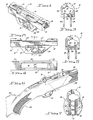
- FIG. 5 With referfence to Figure 5, there is seen a second embodiment of the invention wherein the rigidity is even further increased due to a transverse lateral plate 28 which is fixedly coupled between vertical plates 24 and 25. Furthermore, plate 28, when properly positioned, serves as a loading platform such that a cartridge placed thereon will be engaged by the bolt and urged into the rifle's chamber.
- FIGs 6 and 7. On of the distinct advantages of the inventive receiver is illustrated in Figures 6 and 7. That is, when the inventive receiver is used in connection with a rifle having a single piece stock 30 extending continuously between butt 33 and forearm 32 and having a trigger assembly 34, plates 24 and 25 may be inserted downwardly into stock 30 and hidden thereby. The cartridge magazine 35 is then inserted between plates 24 and 25 as is shown in Figure 7. Thus, rigidity has been increased without detracting from the overall appearance of the weapon.
- the magazine or receiver port is in substantial alignment with the magazine opening in the stock.
- plate 24 and 25 extend within stock 30 in susbtantial juxtaposition to the respective side walls 37 and 38 of the magazine opening 39. Magazine 35 is received therebetween.
- Figure 6 additional references made to Figure 6 in which is seen barrel 40 engaged within threaded opening 15 and presenting firing chamber 42 within forward receiver ring 12.
- Plates 44 and 45 are affixed to receiver 10.
- Plates 44 and 45 are generally analogous to previously described plates 24 and 25, respectively, and are affixed to receiver 10 as set forth above. Plates 44 and 45 deviate from the previously described plates by virtue of countersunk apertures 48. In accordance with the immediately preferred embodiment of the invention, two such openings are formed in each plate. Further provided is an insert generally designated by the reference character 49.
- insert 49 is in the form of a generally rectangular block sized to be received between plates 44 and 45, as better seen in Figure 11.
- Top 50 includes a longitudinally extending recess 52 which functions as a loading platform.
- Sides 53 and 54 reside in substantial juxtaposition with plates 44 and 45, respectively.
- Attachment means for securing insert 49 includes threaded apertures 55 extending inwardly from sides 53 and 54 and receiving flathead machine screws 57 extending through countersunk apertures 48.
- Insert 49 in similarity to lateral plate 28, further increases rigidity and provides a loading platform. Additionally, insert 49 functions to increase the weight of the rifle when desired. Accordingly, a previously reinforced, lightweight hunting rifle may be converted into a target rifle when desired. Insert 49 may be readily fabricated of various materials of differing weights, such as aluminium, steel or brass. Accordingly, the optional weight may be selectively varied to achieve the balance desired by the individual shooter.
- insert 60 is sized to be received between plates 44 and 45 and includes recess 52 and threaded apertures 55. A portion 62 has been removed such that insert 60 weighs less than insert 49. The overall weight of insert 60 is directly proportional to the size of the cavity or portion 62. A series of inserts of varying weights may be provided.
Landscapes
- Engineering & Computer Science (AREA)
- General Engineering & Computer Science (AREA)
- Aiming, Guidance, Guns With A Light Source, Armor, Camouflage, And Targets (AREA)
- Acyclic And Carbocyclic Compounds In Medicinal Compositions (AREA)
- Telescopes (AREA)
- Portable Nailing Machines And Staplers (AREA)
- Saccharide Compounds (AREA)
Priority Applications (1)
| Application Number | Priority Date | Filing Date | Title |
|---|---|---|---|
| AT86301952T ATE43710T1 (de) | 1985-03-21 | 1986-03-18 | Konstruktion fuer zylinderverschlussgewehr. |
Applications Claiming Priority (2)
| Application Number | Priority Date | Filing Date | Title |
|---|---|---|---|
| US714961 | 1985-03-21 | ||
| US06/714,961 US4601124A (en) | 1983-01-31 | 1985-03-21 | Apparatus for increasing the rigidity of a rifle action receiver |
Publications (2)
| Publication Number | Publication Date |
|---|---|
| EP0195645A1 true EP0195645A1 (de) | 1986-09-24 |
| EP0195645B1 EP0195645B1 (de) | 1989-05-31 |
Family
ID=24872186
Family Applications (1)
| Application Number | Title | Priority Date | Filing Date |
|---|---|---|---|
| EP86301952A Expired EP0195645B1 (de) | 1985-03-21 | 1986-03-18 | Konstruktion für Zylinderverschlussgewehr |
Country Status (8)
| Country | Link |
|---|---|
| US (1) | US4601124A (de) |
| EP (1) | EP0195645B1 (de) |
| AT (1) | ATE43710T1 (de) |
| AU (1) | AU590749B2 (de) |
| BR (1) | BR8601241A (de) |
| CA (1) | CA1269268A (de) |
| DE (1) | DE3663738D1 (de) |
| NZ (1) | NZ215283A (de) |
Cited By (1)
| Publication number | Priority date | Publication date | Assignee | Title |
|---|---|---|---|---|
| EP0979986A3 (de) * | 1998-08-13 | 2000-10-11 | STEYR MANNLICHER Aktiengesellschaft & Co. KG | Pistole, deren Gehaüse aus Kunststoff besteht |
Families Citing this family (33)
| Publication number | Priority date | Publication date | Assignee | Title |
|---|---|---|---|---|
| USD329078S (en) | 1990-02-20 | 1992-09-01 | Harold Hasselbush | Firearm receiver |
| US6367188B1 (en) * | 2000-09-05 | 2002-04-09 | Eugene T. Vargas Revocable Trust | Firearm with detachable magazine |
| US20050115128A1 (en) * | 2003-05-15 | 2005-06-02 | Hahin Robert G. | Single loading enhancement device for firearm |
| US20040226211A1 (en) * | 2003-05-16 | 2004-11-18 | Ra Brands. L.L.C. | Composite receiver for firearms |
| US8621773B2 (en) | 2003-06-13 | 2014-01-07 | Battenfeld Technologies, Inc. | Shooting rests for supporting firearms |
| US8011129B2 (en) | 2003-06-13 | 2011-09-06 | Battenfeld Technologies, Inc. | Recoil-reducing shooting rest |
| US7584690B2 (en) | 2004-11-10 | 2009-09-08 | Battenfeld Technologies, Inc. | Firearm vise |
| US7631877B2 (en) | 2006-01-26 | 2009-12-15 | Battenfeld Technologies, Inc. | Firearm targets and methods for manufacturing firearm targets |
| US7681886B2 (en) | 2006-02-24 | 2010-03-23 | Battenfeld Technologies, Inc. | Shooting gallery devices and methods |
| US8104212B2 (en) | 2006-02-24 | 2012-01-31 | Battenfeld Technologies, Inc. | Firearm supports, such as shooting bags, and firearm support assemblies |
| US7726478B2 (en) | 2006-02-27 | 2010-06-01 | Battenfeld Technologies, Inc. | Containers for carrying firearm accessories and/or supporting firearms |
| US7779572B2 (en) | 2006-05-08 | 2010-08-24 | Battenfeld Technologies, Inc. | Bipod device for use with a firearm |
| US8371057B2 (en) | 2006-05-09 | 2013-02-12 | Battenfeld Technologies, Inc. | Firearm cleaning apparatus with protective coating |
| WO2008091394A2 (en) | 2006-08-22 | 2008-07-31 | Battenfeld Technologies, Inc. | Adjustable shooting rests and shooting rest assemblies |
| US7774972B2 (en) | 2006-09-11 | 2010-08-17 | Battenfeld Technologies, Inc. | Modular shooting rests and shooting rest assemblies |
| US8296988B2 (en) | 2006-11-30 | 2012-10-30 | Battenfeld Technologies, Inc. | Firearm supporting devices, methods of assembling firearm supporting devices, and methods of packaging firearm supporting devices |
| US7954272B2 (en) | 2007-05-08 | 2011-06-07 | Battenfeld Technologies, Inc. | Adjustable firearm supports and associated methods of use and manufacture |
| US8336708B2 (en) | 2007-07-20 | 2012-12-25 | Battenfeld Technologies, Inc. | System and container for organizing and carrying tools and tool sets |
| US20090025267A1 (en) * | 2007-07-26 | 2009-01-29 | Alliant Techsystems Inc. | Firearm Rest |
| US7845267B2 (en) | 2007-09-11 | 2010-12-07 | Battenfield Technologies, Inc. | Attachment mechanisms for coupling firearms to supporting structures |
| US7997021B2 (en) | 2008-11-21 | 2011-08-16 | Battenfeld Technologies | Shooting rests with adjustable height assemblies |
| US9140520B2 (en) * | 2010-10-28 | 2015-09-22 | John M. Lopes | Firearm and chassis system |
| US8695985B2 (en) | 2011-01-07 | 2014-04-15 | Battenfeld Technologies, Inc. | Stowable shooting target assemblies |
| US8931201B2 (en) | 2012-12-31 | 2015-01-13 | Battenfeld Technologies, Inc. | Gun support apparatus |
| US10330406B2 (en) * | 2015-07-30 | 2019-06-25 | Craig A. Christensen | Firearm lower receiver with non-detachable magazine |
| US9702653B2 (en) | 2015-10-09 | 2017-07-11 | Battenfeld Technologies, Inc. | Firearm shooting rest |
| GB2548791A (en) * | 2016-02-23 | 2017-10-04 | Trendall Simon | An improved receiver for fireams |
| US10859342B2 (en) * | 2016-04-29 | 2020-12-08 | H-S Precision, Inc. | Firearm stock with barrel-centering feature |
| US10514225B2 (en) | 2018-01-17 | 2019-12-24 | Battenfeld Technologies, Inc. | Firearm shooting rest |
| US10782085B2 (en) | 2019-02-15 | 2020-09-22 | Aob Products Company | Recoil-reducing firearm shooting rest having tank |
| US11841108B2 (en) | 2019-12-17 | 2023-12-12 | Aob Products Company | Multi-legged equipment support having leg angle adjustment |
| US12004658B2 (en) | 2021-04-15 | 2024-06-11 | Aob Products Company | Shooting rest chair |
| WO2025122629A1 (en) * | 2023-12-04 | 2025-06-12 | Mccreight Bobby | 3d printed bolt receiver with reinforcing blade and picatinny rail |
Citations (7)
| Publication number | Priority date | Publication date | Assignee | Title |
|---|---|---|---|---|
| US2356257A (en) * | 1939-11-28 | 1944-08-22 | Remington Arms Co Inc | Firearm |
| CH234375A (de) * | 1941-02-15 | 1944-09-30 | Steyr Daimler Puch Ag | Mehrladegewehr. |
| US3380182A (en) * | 1967-01-03 | 1968-04-30 | Browning Ind Inc | Receiver-stock assembly for firearm |
| US3739515A (en) * | 1971-04-07 | 1973-06-19 | Firearm Dev Inc | Shoulder stock and receiver combination for firearms |
| FR2493501A1 (fr) * | 1980-11-06 | 1982-05-07 | Harang Remy | Contrepoids adaptable pour pistolet a air |
| EP0081136A2 (de) * | 1981-12-08 | 1983-06-15 | Feinwerkbau Westinger & Altenburger GmbH & Co. KG | Gewehr für Sportzwecke |
| EP0115411A2 (de) * | 1983-01-31 | 1984-08-08 | STURM, RUGER & COMPANY, INC. | Gewehrverschlussgehäuse |
Family Cites Families (4)
| Publication number | Priority date | Publication date | Assignee | Title |
|---|---|---|---|---|
| CA234375A (en) * | 1923-09-18 | Frederick Marcus | Gravity propelled vehicle | |
| US1376834A (en) * | 1920-07-09 | 1921-05-03 | Us Ordnance Co | Automatic firearm |
| US2611204A (en) * | 1947-11-28 | 1952-09-23 | Marlin Firearms Co | Receiver and action assembly for firearms |
| US2795881A (en) * | 1956-02-09 | 1957-06-18 | Orren W Bellows | Gun receiver reinforcing sleeve |
-
1985
- 1985-03-21 US US06/714,961 patent/US4601124A/en not_active Expired - Fee Related
-
1986
- 1986-02-25 NZ NZ215283A patent/NZ215283A/en unknown
- 1986-03-18 AT AT86301952T patent/ATE43710T1/de not_active IP Right Cessation
- 1986-03-18 DE DE8686301952T patent/DE3663738D1/de not_active Expired
- 1986-03-18 EP EP86301952A patent/EP0195645B1/de not_active Expired
- 1986-03-20 BR BR8601241A patent/BR8601241A/pt unknown
- 1986-03-21 AU AU55008/86A patent/AU590749B2/en not_active Ceased
- 1986-03-21 CA CA000504697A patent/CA1269268A/en not_active Expired
Patent Citations (7)
| Publication number | Priority date | Publication date | Assignee | Title |
|---|---|---|---|---|
| US2356257A (en) * | 1939-11-28 | 1944-08-22 | Remington Arms Co Inc | Firearm |
| CH234375A (de) * | 1941-02-15 | 1944-09-30 | Steyr Daimler Puch Ag | Mehrladegewehr. |
| US3380182A (en) * | 1967-01-03 | 1968-04-30 | Browning Ind Inc | Receiver-stock assembly for firearm |
| US3739515A (en) * | 1971-04-07 | 1973-06-19 | Firearm Dev Inc | Shoulder stock and receiver combination for firearms |
| FR2493501A1 (fr) * | 1980-11-06 | 1982-05-07 | Harang Remy | Contrepoids adaptable pour pistolet a air |
| EP0081136A2 (de) * | 1981-12-08 | 1983-06-15 | Feinwerkbau Westinger & Altenburger GmbH & Co. KG | Gewehr für Sportzwecke |
| EP0115411A2 (de) * | 1983-01-31 | 1984-08-08 | STURM, RUGER & COMPANY, INC. | Gewehrverschlussgehäuse |
Cited By (1)
| Publication number | Priority date | Publication date | Assignee | Title |
|---|---|---|---|---|
| EP0979986A3 (de) * | 1998-08-13 | 2000-10-11 | STEYR MANNLICHER Aktiengesellschaft & Co. KG | Pistole, deren Gehaüse aus Kunststoff besteht |
Also Published As
| Publication number | Publication date |
|---|---|
| DE3663738D1 (en) | 1989-07-06 |
| EP0195645B1 (de) | 1989-05-31 |
| BR8601241A (pt) | 1986-12-02 |
| US4601124A (en) | 1986-07-22 |
| AU590749B2 (en) | 1989-11-16 |
| NZ215283A (en) | 1988-05-30 |
| AU5500886A (en) | 1986-09-25 |
| CA1269268A (en) | 1990-05-22 |
| ATE43710T1 (de) | 1989-06-15 |
Similar Documents
| Publication | Publication Date | Title |
|---|---|---|
| EP0195645B1 (de) | Konstruktion für Zylinderverschlussgewehr | |
| US7937874B2 (en) | Firearm grips and firearm grip construction sets | |
| US8484877B2 (en) | Rifle upper receiver with integral magazine well | |
| US9631885B2 (en) | Rifle stock assembly for different barreled receivers | |
| US7305789B2 (en) | Reversible weapon telescope mount | |
| EP2943733B1 (de) | Austauschbares schaftsystem für feuerwaffen | |
| US7665240B1 (en) | Modular system rifle stock | |
| US5123194A (en) | Rifle barrel truss mounting | |
| US7610712B2 (en) | Adjustable rear pistol sight | |
| US5149899A (en) | Gunstock having interchangeable combs | |
| US8028458B2 (en) | Housing for a rifle | |
| US3611607A (en) | Firearm conversion system | |
| US20070089347A1 (en) | Easy connect stock and forend system | |
| US20070199225A1 (en) | Accessory Rail Assembly for Firearms | |
| US7165352B2 (en) | Rifle with trigger pull weight adjustment | |
| US10976127B2 (en) | Accessory attachment system for a handgun having a polymer slide cover | |
| FI86338B (fi) | Handvapen med en kolv. | |
| EP1625342B1 (de) | Verbundwerkstoffgehäuse für feuerwaffen | |
| US5481818A (en) | Gun sight mounting system | |
| US12455126B2 (en) | Modular frame and chassis system for a firearm | |
| US4440062A (en) | Reversible bolt for firearms | |
| CA1122837A (en) | Platform ramp sight for firearms | |
| US4244114A (en) | Stepped platform ramp sight for firearms | |
| US3726037A (en) | Shotgun | |
| US4713903A (en) | Choke assemblies for shotguns |
Legal Events
| Date | Code | Title | Description |
|---|---|---|---|
| PUAI | Public reference made under article 153(3) epc to a published international application that has entered the european phase |
Free format text: ORIGINAL CODE: 0009012 |
|
| AK | Designated contracting states |
Kind code of ref document: A1 Designated state(s): AT BE CH DE FR GB IT LI LU NL SE |
|
| 17P | Request for examination filed |
Effective date: 19860917 |
|
| 17Q | First examination report despatched |
Effective date: 19871204 |
|
| GRAA | (expected) grant |
Free format text: ORIGINAL CODE: 0009210 |
|
| AK | Designated contracting states |
Kind code of ref document: B1 Designated state(s): AT BE CH DE FR GB IT LI LU NL SE |
|
| PG25 | Lapsed in a contracting state [announced via postgrant information from national office to epo] |
Ref country code: NL Effective date: 19890531 |
|
| REF | Corresponds to: |
Ref document number: 43710 Country of ref document: AT Date of ref document: 19890615 Kind code of ref document: T |
|
| ITF | It: translation for a ep patent filed | ||
| REF | Corresponds to: |
Ref document number: 3663738 Country of ref document: DE Date of ref document: 19890706 |
|
| ET | Fr: translation filed | ||
| NLV1 | Nl: lapsed or annulled due to failure to fulfill the requirements of art. 29p and 29m of the patents act | ||
| PLBE | No opposition filed within time limit |
Free format text: ORIGINAL CODE: 0009261 |
|
| STAA | Information on the status of an ep patent application or granted ep patent |
Free format text: STATUS: NO OPPOSITION FILED WITHIN TIME LIMIT |
|
| 26N | No opposition filed | ||
| ITTA | It: last paid annual fee | ||
| PGFP | Annual fee paid to national office [announced via postgrant information from national office to epo] |
Ref country code: GB Payment date: 19930308 Year of fee payment: 8 |
|
| PGFP | Annual fee paid to national office [announced via postgrant information from national office to epo] |
Ref country code: FR Payment date: 19930309 Year of fee payment: 8 |
|
| PGFP | Annual fee paid to national office [announced via postgrant information from national office to epo] |
Ref country code: AT Payment date: 19930311 Year of fee payment: 8 |
|
| PGFP | Annual fee paid to national office [announced via postgrant information from national office to epo] |
Ref country code: SE Payment date: 19930315 Year of fee payment: 8 |
|
| PGFP | Annual fee paid to national office [announced via postgrant information from national office to epo] |
Ref country code: DE Payment date: 19930324 Year of fee payment: 8 |
|
| PGFP | Annual fee paid to national office [announced via postgrant information from national office to epo] |
Ref country code: CH Payment date: 19930325 Year of fee payment: 8 |
|
| PGFP | Annual fee paid to national office [announced via postgrant information from national office to epo] |
Ref country code: LU Payment date: 19930421 Year of fee payment: 8 |
|
| PGFP | Annual fee paid to national office [announced via postgrant information from national office to epo] |
Ref country code: BE Payment date: 19930504 Year of fee payment: 8 |
|
| EPTA | Lu: last paid annual fee | ||
| PG25 | Lapsed in a contracting state [announced via postgrant information from national office to epo] |
Ref country code: LU Free format text: LAPSE BECAUSE OF NON-PAYMENT OF DUE FEES Effective date: 19940318 Ref country code: GB Effective date: 19940318 Ref country code: AT Effective date: 19940318 |
|
| PG25 | Lapsed in a contracting state [announced via postgrant information from national office to epo] |
Ref country code: SE Free format text: LAPSE BECAUSE OF NON-PAYMENT OF DUE FEES Effective date: 19940319 |
|
| PG25 | Lapsed in a contracting state [announced via postgrant information from national office to epo] |
Ref country code: LI Effective date: 19940331 Ref country code: CH Effective date: 19940331 Ref country code: BE Effective date: 19940331 |
|
| BERE | Be: lapsed |
Owner name: STURM RUGER & CY INC. Effective date: 19940331 |
|
| GBPC | Gb: european patent ceased through non-payment of renewal fee |
Effective date: 19940318 |
|
| PG25 | Lapsed in a contracting state [announced via postgrant information from national office to epo] |
Ref country code: FR Effective date: 19941130 |
|
| REG | Reference to a national code |
Ref country code: CH Ref legal event code: PL |
|
| PG25 | Lapsed in a contracting state [announced via postgrant information from national office to epo] |
Ref country code: DE Effective date: 19941201 |
|
| REG | Reference to a national code |
Ref country code: FR Ref legal event code: ST |
|
| EUG | Se: european patent has lapsed |
Ref document number: 86301952.7 Effective date: 19941010 |
|
| PG25 | Lapsed in a contracting state [announced via postgrant information from national office to epo] |
Ref country code: IT Free format text: LAPSE BECAUSE OF NON-PAYMENT OF DUE FEES;WARNING: LAPSES OF ITALIAN PATENTS WITH EFFECTIVE DATE BEFORE 2007 MAY HAVE OCCURRED AT ANY TIME BEFORE 2007. THE CORRECT EFFECTIVE DATE MAY BE DIFFERENT FROM THE ONE RECORDED. Effective date: 20050318 |