EP0195653B1 - Drehbar miteinander verbundene starre Zellenketten - Google Patents
Drehbar miteinander verbundene starre Zellenketten Download PDFInfo
- Publication number
- EP0195653B1 EP0195653B1 EP86301988A EP86301988A EP0195653B1 EP 0195653 B1 EP0195653 B1 EP 0195653B1 EP 86301988 A EP86301988 A EP 86301988A EP 86301988 A EP86301988 A EP 86301988A EP 0195653 B1 EP0195653 B1 EP 0195653B1
- Authority
- EP
- European Patent Office
- Prior art keywords
- group
- hinge
- cell
- adjacent
- cells
- Prior art date
- Legal status (The legal status is an assumption and is not a legal conclusion. Google has not performed a legal analysis and makes no representation as to the accuracy of the status listed.)
- Expired - Lifetime
Links
- 230000001902 propagating effect Effects 0.000 claims description 5
- 230000008878 coupling Effects 0.000 claims description 4
- 238000010168 coupling process Methods 0.000 claims description 4
- 238000005859 coupling reaction Methods 0.000 claims description 4
- 239000007787 solid Substances 0.000 description 3
- 239000002689 soil Substances 0.000 description 2
- 238000010276 construction Methods 0.000 description 1
- 239000011521 glass Substances 0.000 description 1
- 239000000463 material Substances 0.000 description 1
- 238000000465 moulding Methods 0.000 description 1
- 229920003023 plastic Polymers 0.000 description 1
- 239000004033 plastic Substances 0.000 description 1
- 230000000644 propagated effect Effects 0.000 description 1
- 230000000717 retained effect Effects 0.000 description 1
Images

Classifications
-
- A—HUMAN NECESSITIES
- A01—AGRICULTURE; FORESTRY; ANIMAL HUSBANDRY; HUNTING; TRAPPING; FISHING
- A01C—PLANTING; SOWING; FERTILISING
- A01C1/00—Apparatus, or methods of use thereof, for testing or treating seed, roots, or the like, prior to sowing or planting
- A01C1/04—Arranging seed on carriers, e.g. on tapes, on cords ; Carrier compositions
- A01C1/042—Tapes, bands or cords
-
- A—HUMAN NECESSITIES
- A01—AGRICULTURE; FORESTRY; ANIMAL HUSBANDRY; HUNTING; TRAPPING; FISHING
- A01G—HORTICULTURE; CULTIVATION OF VEGETABLES, FLOWERS, RICE, FRUIT, VINES, HOPS OR SEAWEED; FORESTRY; WATERING
- A01G9/00—Cultivation in receptacles, forcing-frames or greenhouses; Edging for beds, lawn or the like
- A01G9/02—Receptacles, e.g. flower-pots or boxes; Glasses for cultivating flowers
- A01G9/029—Receptacles for seedlings
- A01G9/0295—Units comprising two or more connected receptacles
Definitions
- the present invention relates to connected individual cells intended for use in the mechanized propagation of seeds and the handling of plants propagated therein.
- the invention relates to a cell as described in our Australian Patent Specification No. 516,117.
- Cell chains are known wherein the cells are each tubular cylindrical constructions of substantially uniform cross-section with pivot connections formed between adjacent cells. These chains are moved between desired locations by drive sprocket wheels engaging essentially between the tubular cells with the open face of the cell directed upwardly to receive propagating material and a seed. While these cell chains are effective in operation they do suffer from certain practical disadvantages. Cell chains of this type because of their pivot arrangements between cells are stored in a circular spiral manner which take up considerable space both between individual cells and by the fact that a circular array of cells leaves substantial areas which cannot be occupied by cells.
- U.S. Patent Specification No. 4,167,911 discloses a plurality of individual cells, each of which is joined to the next adjacent cell by a thin, deliberately weakened paper or film connector. Not only are the connectors formed of weakened paper or film, but the cells themselves are formed of paper of the kind that is rottable or degradable, thereby enabling each individual cell to be separated from its adjacent cells and planted along with the seedling and its propagating medium.
- the disclosure is therefore such as to provide a plurality of containers which are initially linked by a weak connecting link but are subsequently separated and therefore consumed during seedling planting.
- the objective of the present invention is therefore to provide a reusable cell chain arrangement which will overcome or substantially minimise the aforementioned disadvantages associated with the known arrangements.
- the present invention provides a device for use in propagating plants comprising a plurality of open top individual cells joined to one another in an elongate row, said device being characterised in that the open top individual cells are held together in a rigid group (10) having opposed ends, first hinge means (12') carried at one end of said group (10), second hinge means (20, 21b) carried at an opposite end of said group (10), the first hinge means (12') at said one end of said group (10) being engageable with the second hinge means (20, 21b) of a like said group (11) to form a hinge connection (13) to enable pivotal coupling of said groups together whereby said first and second hinge means (12', 20, 21b) enables said one group (10) to pivot relative to an adjacent said like group (11) when interconnected in at least one direction through an arc of such length as to locate said one group (10) and said adjacent like group (11) substantially parallel to one another in side by side relation.
- the individual cells in each group of cells are arranged in a straight line and the arrangement is such as to allow groups of cells to lie side by side in storage positions to make up a rectangular array of individual cells.
- a cell chain including a plurality of containers for holding seeds or seedlings and propagating medium therein, the containers being interconnected by at least one link formed and located in such a way that a tooth of a toothed driving means may interengage the link and/or the containers for moving the cell chain from one point to another.
- the cross sectional shape of the containers may vary from circular, hexagonal, square or the like depending upon the desired mode of stacking and use of the invention, and the invention is not limited to any specific container shape.
- the chain can be easily produced as a plastics moulding.
- the containers may be formed with a bottom or alternatively, with inwardly tapered walls to prevent loss of soil therein.
- the containers may be shaped with hexagonal cross section thereby facilitating close stacking in straight lines.
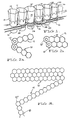
- the cell chain may consist of a series of cells or plant compartments rigidly connected to form rigid groups containing a number of cells. Each group may be pivoted at either end using a link cell which will allow the previous and the following group to pivot about each other. In this way a continuous chain of alternating cell groups and links can be concertined into a solid block of cells to allow ease of handling and storage.
- the cell chain may be broken at any point where a link cell exists.
- the plant cells may vary in shape and size between derivatives of the cell chain. Some possibilities include conical shapes, cylinders and tapered hexagons. Provision can be made between each cell for engagement with a toothed driving means when the chain is straightened into a single strand.
- the link cell is uniquely designed to allow the rigid cell groups to hinge in either direction but still allow the cells to nest against each other to form a pack of hexagonal cells to appear as a solid sheet of honeycomb.
- the unique feature of the product is that in the packed configuration the container forms a rectangular mass able to maximize the use of space and fit in with standard horticultural practice in existing glass houses.
- the pack When hinged apart (or straightened) the pack transforms into a single line of hinged cell groups of hexagonal cells, able to be mechanically handled at high speed in single file to select and transplant the soil block (plug) and plant at high speed.
- Each of the cells has a polygonal, preferably regular/hexagonal open upper face 14 with a hollow body 15 tapering downwardly to a drainage opening 16 in the base of the cell.
- the drainage opening 16 comprises a restricted passage 17 together with a widening lower section 18.
- Each group of cells 10, 11 comprise cells 12 arranged rigidly in line.
- the number of cells in each group may be variable.
- the last cell 12' in each group has a curved outer face 19 allowing for pivoting movement of the group relative to the hinge element 13 as will hereinafter be explained.
- the other end of the group includes a pivot connecting collar 20 enabling the group to be hingedly connected to the hinge element 13.
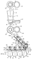
- the hinge element 13 is shown in greater detail in Figures 5 a, b and c.
- the hinge element preferably comprises a single propagation cell 21 with a connecting hinge collar 22 equivalent to the collar 20 of the cell groups.
- a double pivot hinge is formed between the adjacent cell groups 10, 11.
- the rigid element 12 has stop means 27, 28 arranged to limit pivoting movement but permitting pivoting in both directions from the centre line of the rigidly connected cells to a degree sufficient to allow the groups of cells to lie adjacent one another in a stcorage position.
- the individual cells 12 are interconnected in each group by a pair of rigid webs 25, 26.
- the polygonal upper face of the cells are so arranged whereby adjacent groups of cells are adapted to nest into one another with substantially no space between adjacent cells. In this manner a substantially rectangular array of cells can be formed in a storage position with minimum wastage of space.
- FIG. 6 shows a slightly modified form of the invention comprising a number of rigidly interconnected individual cells 12 having essentially hexagonal upper faces 14 forming rigid groups of in line cells 10 and 11.
- a hinge element 13 joins the two groups.
- the hinge element comprises a cell 21 having a base section 21 press fitted but retained for pivoting movement within a retaining ring 21b rigidly formed at the end of the group 10 of the rigidly connected cells.
- the hinge element 13 further includes a ring or collar 13' extending laterally from the cell 21 which press fits in a pivoting manner over the base section 12b of the end cell 12' of the rigid group of cells 11. In this manner, a double hinge connection is formed.
- a pair of web structures 25 and 26 hold the cells 12, 12' together and lateral projections 26' are provided between the webs and extending outwardly beyond the webs to be located within the space 26b between the webs when the groups of cells are folded to be nested into one another in side by side relationship.
- a pair of stop projections 27 are provided on a flange section 27' of the rigid element 12. The stop projections limit the rotation of the hinge element to substantially equal amounts on either side of the centre line of the group of cells 10 and 11.
- the embodiment of Figure 6 is essentially similar to the embodiment illustrated in Figures 1 to 5.
Landscapes
- Life Sciences & Earth Sciences (AREA)
- Environmental Sciences (AREA)
- Soil Sciences (AREA)
- Cultivation Receptacles Or Flower-Pots, Or Pots For Seedlings (AREA)
Claims (15)
- Vorrichtung zur Verwendung um Pflanzen zu vermehren, die eine Vielzahl von einzelnen, oben offenen Zellen umfasst, die miteinander in einer langgestreckten Reihe verbunden sind, wobei die Vorrichtung dadurch gekennzeichnet ist, dass die einzelnen, oben offenen Zellen in einer stabilen Gruppe (10) mit entgegengesetzten Enden zusammengehalten werden, mit einem ersten Gelenk (12'), das an einem Ende der Gruppe (10) getragen wird, einem zweiten Gelenk (20, 21b), das an dem entgegengesetzten Ende der Gruppe (10) getragen wird, wobei das erste Gelenk (12') an dem einen Ende der Gruppe (10) mit dem zweiten Gelenk (20, 21b) einer gleichen solchen Gruppe (11) in Verbindung gebracht werden kann, um eine Gelenkverbindung (13) zu bilden, um schwenkbare Verbindung der Gruppen miteinander zu ermöglichen, wobei das erste und zweite Gelenk (12', 20, 21b) die eine Gruppe (10) befähigt, relativ zu einer benachbarten gleichen Gruppe (11) zu schwenken, wenn sie in wenigsten einer Richtung durch einen Bogen solcher Länge miteinander verbunden sind, um die eine Gruppe (10) und die benachbarte gleiche Gruppe (11) im wesentlichen parallel zueinander in einer nebeneinanderliegenden Beziehung anzuordnen.
- Vorrichtung nach Anspruch 1, dadurch gekennzeichnet, dass die eine Gruppe (10) mit der benachbarten Gruppe (11) durch die Gelenkverbindung (13) verbunden ist.
- Vorrichtung nach Anspruch 2, dadurch gekennzeichnet, dass die Gelenkverbindung die benachbarte Gruppe (11) befähigt, sich zur Verlängerung der einen Gruppe (10) längs einer geraden Linie zu erstrecken.
- Vorrichtung nach Anspruch 2, dadurch gekennzeichnet, dass die Zellen (12) der Gruppen (10, 11) versetzt angeordnet sind, wenn die Gruppen (10, 11) schwenkbar gelagert sind, um sich nebeneinander und im wesentlichen parallel zueinander zu erstrecken.
- Vorrichtung nach Anspruch 2, dadurch gekennzeichnet, dass die Gelenkverbindung (13) die eine Gruppe (10) befähigt, relativ zu der benachbarten Gruppe (11) in irgendeine von zwei entgegengesetzten Richtungen zu schwenken, um die eine Gruppe (10) und die benachbarte Gruppe (11) in einer im wesentlichen parallelen, nebeneinanderliegenden Beziehung anzuordnen.
- Vorrichtung nach Anspruch 2, dadurch gekennzeichnet, dass die Gelenkverbindung (13) ein Begrenzungsmittel (27, 28) einschliesst, um relative Schwenkbewegung der benachbarten Gruppen (10, 11) zu begrenzen.
- Vorrichtung nach Anspruch 2, dadurch gekennzeichnet, dass jede der Gruppen (10, 11) eine entfernteste Zelle (12') hat, die mit einer gekrümmten äusseren Oberfläche (19) gebildet ist.
- Vorrichtung nach Anspruch 7, dadurch gekennzeichnet, dass die entfernteste Zelle (12') nur an einem Ende der zugeordneten Gruppe (10, 11) liegt.
- Vorrichtung nach Anspruch 2, dadurch gekennzeichnet, dass die Gelenkverbindung (13) einen Bund (20, 21b) einschliesst, in dem ein unteres Ende einer entferntesten Zelle (12') drehbar angeordnet ist.
- Vorrichtung nach Anspruch 9, dadurch gekennzeichnet, dass die Gelenkverbindung (13) einen Bund (22) einschliesst, der von einer Zelle (21) getragen wird und davon hervorragt, welche ihr unteres Ende drehbar in dem Bund (20, 21b) angeordnet hat.
- Vorrichtung nach Anspruch 1, dadurch gekennzeichnet, dass das erste Gelenk einen Bund (20, 21b) umfasst, der sich über ein Ende der ersten Gruppe (10) hinaus erstreckt.
- Vorrichtung nach Anspruch 11, dadurch gekennzeichnet, dass das Gelenk eine Zelle (12') umfasst, die an ihrem unteren Ende eine Hülse mit einer derartigen Grösse hat, um drehbar in dem Bund (20, 21b) angeordnet zu werden.
- Vorrichtung nach Anspruch 11, dadurch gekennzeichnet, dass das erste Gelenk weiterhin ein Gelenkelement einschliesst, das eine Zelle (21) mit einem unteren Ende umfasst, welches schwenkbar mit dem Bund (20, 21b) verbunden ist, und einen zweiten Bund (22), der sich von der Zelle (21) erstreckt.
- Vorrichtung nach Anspruch 1, dadurch gekennzeichnet, dass ein Verbindungselement (13) mit dem zweiten Gelenk (20, 21b) schwenkbar verbunden ist, wobei das Verbindungselement zur Schwenkverbindung mit dem ersten Gelenk (12') einer gleichen solchen Gruppe angeordnet ist.
- Vorrichtung nach einem der Ansprüche 1 bis 14, dadurch gekennzeichnet, dass die eine Gruppe (10) wenigstens ein Eingriffsglied (26') einschliesst, das mit dem Abstandhalter (25, 26) einer benachbarten solchen gleichen Gruppe zusammenwirken kann, wenn die Gruppen parallel zueinander in einer nebeneinanderliegenden Beziehung angeordnet sind.
Priority Applications (1)
| Application Number | Priority Date | Filing Date | Title |
|---|---|---|---|
| AT86301988T ATE78129T1 (de) | 1985-03-19 | 1986-03-18 | Drehbar miteinander verbundene starre zellenketten. |
Applications Claiming Priority (5)
| Application Number | Priority Date | Filing Date | Title |
|---|---|---|---|
| AU9818/85 | 1985-03-19 | ||
| AUPG981885 | 1985-03-19 | ||
| AU3301/85 | 1985-11-06 | ||
| AUPH330185 | 1985-11-06 | ||
| AU54924/86A AU591102B2 (en) | 1985-03-19 | 1986-03-18 | Improvements relating to cell chains |
Publications (3)
| Publication Number | Publication Date |
|---|---|
| EP0195653A2 EP0195653A2 (de) | 1986-09-24 |
| EP0195653A3 EP0195653A3 (en) | 1988-02-24 |
| EP0195653B1 true EP0195653B1 (de) | 1992-07-15 |
Family
ID=27154959
Family Applications (1)
| Application Number | Title | Priority Date | Filing Date |
|---|---|---|---|
| EP86301988A Expired - Lifetime EP0195653B1 (de) | 1985-03-19 | 1986-03-18 | Drehbar miteinander verbundene starre Zellenketten |
Country Status (1)
| Country | Link |
|---|---|
| EP (1) | EP0195653B1 (de) |
Families Citing this family (3)
| Publication number | Priority date | Publication date | Assignee | Title |
|---|---|---|---|---|
| US4926587A (en) * | 1986-11-21 | 1990-05-22 | Wingerden Aart Van | Method and apparatus for propagating plants |
| NL1009527C2 (nl) * | 1998-06-30 | 2000-01-18 | V O F Gebr Smak & Zn | Gewas-tray alsmede teeltsysteem voorzien van een dergelijke gewas-tray. |
| BR102018001526B1 (pt) * | 2018-01-24 | 2023-02-23 | Éder Alexandre Buscarato | Transplantadora de mudas |
Family Cites Families (6)
| Publication number | Priority date | Publication date | Assignee | Title |
|---|---|---|---|---|
| US2197594A (en) * | 1937-08-05 | 1940-04-16 | Orlo C Lull | Seed and fertilizer tape |
| US4167911A (en) * | 1976-03-02 | 1979-09-18 | Nippon Tensai Seito Kabushiki Kaisha | Apparatus for separation and transplanting paper tube seedlings from a continuous paper tube seedling assembly |
| AU516117B2 (en) * | 1976-09-09 | 1981-05-21 | Williames, G.A. | Chain of seed cultivating containers |
| FR2407664A2 (fr) * | 1977-07-12 | 1979-06-01 | Bully Clos | Amenagement de pepinieres hors sol |
| AU524308B2 (en) * | 1978-10-27 | 1982-09-09 | Williames, G.A. | Conveyor links made of plant containers |
| EP0097735B1 (de) * | 1982-06-30 | 1987-03-04 | Kaiser, Christian, Dr.agr. | Verfahren zur Anzucht und zum Aussetzen von Pflanzen oder Keimlingen |
-
1986
- 1986-03-18 EP EP86301988A patent/EP0195653B1/de not_active Expired - Lifetime
Also Published As
| Publication number | Publication date |
|---|---|
| EP0195653A2 (de) | 1986-09-24 |
| EP0195653A3 (en) | 1988-02-24 |
Similar Documents
| Publication | Publication Date | Title |
|---|---|---|
| US5241784A (en) | Plant root container and method of air root pruning | |
| US5031359A (en) | Garden structure and method of producing same | |
| ES2217426T3 (es) | Bandejas de cultivo mejoradas y mecanismos de manipulacion de las mismas. | |
| US4939865A (en) | Method and container for growing transplantable plants | |
| EP0323674B2 (de) | Behälter für Pflanzen | |
| US4006558A (en) | Seedling plant propagation container | |
| JPH01501677A (ja) | 植物栽培用容器システム | |
| CA1208019A (en) | Seedling propagating container and method | |
| US5934018A (en) | Molded plant tray | |
| CN101711216B (zh) | 用于培养植物的容器及其载体 | |
| US4248014A (en) | Seedling containers | |
| GB1571145A (en) | Plant containers for growing plants to be transplanted | |
| US4159597A (en) | Planting system including articles of manufacture | |
| US4763443A (en) | Cell chains | |
| USRE32808E (en) | Plant propagating container and method | |
| EP3148320B1 (de) | Systeme zum züchten von pflanzen mit luftwurzeln | |
| US6061953A (en) | Potted plant protector device | |
| EP0195653A2 (de) | Drehbar miteinander verbundene starre Zellenketten | |
| CA1301457C (en) | Device for use in propagating plants | |
| US4777764A (en) | Plant growing container and method | |
| CA1104346A (en) | Propagator for growing and transplanting plants | |
| US4216621A (en) | Planting system including articles of manufacture | |
| US5267389A (en) | Container with integrally formed handle | |
| WO1993019583A1 (en) | Propagation cell with means for mechanized handling | |
| WO1997021339A1 (en) | Plant container with transformable walls |
Legal Events
| Date | Code | Title | Description |
|---|---|---|---|
| PUAI | Public reference made under article 153(3) epc to a published international application that has entered the european phase |
Free format text: ORIGINAL CODE: 0009012 |
|
| AK | Designated contracting states |
Kind code of ref document: A2 Designated state(s): AT BE CH DE FR GB IT LI LU NL SE |
|
| PUAL | Search report despatched |
Free format text: ORIGINAL CODE: 0009013 |
|
| AK | Designated contracting states |
Kind code of ref document: A3 Designated state(s): AT BE CH DE FR GB IT LI LU NL SE |
|
| RHK1 | Main classification (correction) |
Ipc: A01G 9/10 |
|
| 17P | Request for examination filed |
Effective date: 19880813 |
|
| 17Q | First examination report despatched |
Effective date: 19891214 |
|
| GRAA | (expected) grant |
Free format text: ORIGINAL CODE: 0009210 |
|
| AK | Designated contracting states |
Kind code of ref document: B1 Designated state(s): AT BE CH DE FR GB IT LI LU NL SE |
|
| PG25 | Lapsed in a contracting state [announced via postgrant information from national office to epo] |
Ref country code: SE Effective date: 19920715 Ref country code: LI Effective date: 19920715 Ref country code: CH Effective date: 19920715 Ref country code: BE Effective date: 19920715 Ref country code: AT Effective date: 19920715 |
|
| REF | Corresponds to: |
Ref document number: 78129 Country of ref document: AT Date of ref document: 19920815 Kind code of ref document: T |
|
| REF | Corresponds to: |
Ref document number: 3685974 Country of ref document: DE Date of ref document: 19920820 |
|
| ITF | It: translation for a ep patent filed | ||
| REG | Reference to a national code |
Ref country code: CH Ref legal event code: PL |
|
| ET | Fr: translation filed | ||
| PGFP | Annual fee paid to national office [announced via postgrant information from national office to epo] |
Ref country code: GB Payment date: 19930309 Year of fee payment: 8 |
|
| PGFP | Annual fee paid to national office [announced via postgrant information from national office to epo] |
Ref country code: FR Payment date: 19930311 Year of fee payment: 8 |
|
| PG25 | Lapsed in a contracting state [announced via postgrant information from national office to epo] |
Ref country code: LU Free format text: LAPSE BECAUSE OF NON-PAYMENT OF DUE FEES Effective date: 19930331 |
|
| PGFP | Annual fee paid to national office [announced via postgrant information from national office to epo] |
Ref country code: NL Payment date: 19930331 Year of fee payment: 8 |
|
| PGFP | Annual fee paid to national office [announced via postgrant information from national office to epo] |
Ref country code: DE Payment date: 19930406 Year of fee payment: 8 |
|
| PLBE | No opposition filed within time limit |
Free format text: ORIGINAL CODE: 0009261 |
|
| STAA | Information on the status of an ep patent application or granted ep patent |
Free format text: STATUS: NO OPPOSITION FILED WITHIN TIME LIMIT |
|
| 26N | No opposition filed | ||
| PG25 | Lapsed in a contracting state [announced via postgrant information from national office to epo] |
Ref country code: GB Effective date: 19940318 |
|
| PG25 | Lapsed in a contracting state [announced via postgrant information from national office to epo] |
Ref country code: NL Effective date: 19941001 |
|
| GBPC | Gb: european patent ceased through non-payment of renewal fee |
Effective date: 19940318 |
|
| NLV4 | Nl: lapsed or anulled due to non-payment of the annual fee | ||
| PG25 | Lapsed in a contracting state [announced via postgrant information from national office to epo] |
Ref country code: FR Effective date: 19941130 |
|
| PG25 | Lapsed in a contracting state [announced via postgrant information from national office to epo] |
Ref country code: DE Effective date: 19941201 |
|
| REG | Reference to a national code |
Ref country code: FR Ref legal event code: ST |
|
| PG25 | Lapsed in a contracting state [announced via postgrant information from national office to epo] |
Ref country code: IT Free format text: LAPSE BECAUSE OF NON-PAYMENT OF DUE FEES;WARNING: LAPSES OF ITALIAN PATENTS WITH EFFECTIVE DATE BEFORE 2007 MAY HAVE OCCURRED AT ANY TIME BEFORE 2007. THE CORRECT EFFECTIVE DATE MAY BE DIFFERENT FROM THE ONE RECORDED. Effective date: 20050318 |