EP0195720A2 - Disposition de ventilation pour disque optique d'enregistrement - Google Patents
Disposition de ventilation pour disque optique d'enregistrement Download PDFInfo
- Publication number
- EP0195720A2 EP0195720A2 EP86400577A EP86400577A EP0195720A2 EP 0195720 A2 EP0195720 A2 EP 0195720A2 EP 86400577 A EP86400577 A EP 86400577A EP 86400577 A EP86400577 A EP 86400577A EP 0195720 A2 EP0195720 A2 EP 0195720A2
- Authority
- EP
- European Patent Office
- Prior art keywords
- disc
- optical recording
- spacer
- bonding material
- recording disc
- Prior art date
- Legal status (The legal status is an assumption and is not a legal conclusion. Google has not performed a legal analysis and makes no representation as to the accuracy of the status listed.)
- Granted
Links
Images




Classifications
-
- G—PHYSICS
- G11—INFORMATION STORAGE
- G11B—INFORMATION STORAGE BASED ON RELATIVE MOVEMENT BETWEEN RECORD CARRIER AND TRANSDUCER
- G11B7/00—Recording or reproducing by optical means, e.g. recording using a thermal beam of optical radiation by modifying optical properties or the physical structure, reproducing using an optical beam at lower power by sensing optical properties; Record carriers therefor
- G11B7/24—Record carriers characterised by shape, structure or physical properties, or by the selection of the material
- G11B7/24015—Air-sandwiched discs
-
- G—PHYSICS
- G11—INFORMATION STORAGE
- G11B—INFORMATION STORAGE BASED ON RELATIVE MOVEMENT BETWEEN RECORD CARRIER AND TRANSDUCER
- G11B7/00—Recording or reproducing by optical means, e.g. recording using a thermal beam of optical radiation by modifying optical properties or the physical structure, reproducing using an optical beam at lower power by sensing optical properties; Record carriers therefor
- G11B7/24—Record carriers characterised by shape, structure or physical properties, or by the selection of the material
- G11B7/26—Apparatus or processes specially adapted for the manufacture of record carriers
Definitions
- the present invention relates to a ventilation type optical recording disc,-more particularly, to a ventilation type optical recording disc comprising one or more of ventilation paths, through which outside air of the optical recording disc passes into the inside air gap of the optical recording disc.
- an optical recording disc has a well known sandwich construction, that is, in the optical recording disc, a pair of disc substrates are bonded together through an inner spacer and an outer spacer, so that each of recording layers of a pair of the disc substrates, which is formed on the surface of the disc substrate, faces together.
- a space which is called “the air gap” below, is formed between the recording layers of both of the disc substrates, wherein the air gap is isolated from the outside of the optical recording disc.
- the optical recording disc comprising the isolated air gap can prevent an alien substance such as dust etc.
- the substance can not enter the air gap, thereby information can be recorded correctly on the recording layer.
- the environment condition of the optical recording disc such as the temperature or the atmospheric pressure changes, there will be a pressure difference between the air gap and the outside of the optical recording disc, and it will be difficult to track and focus on a predetermined tracking line of the recording layer.
- the disc substrate may be broken when the shape of the disc substrate changes.
- an optical recording disc comprising a ventilation path was proposed in the Japanese patent provisional publications Nos. 106204/1979 and 171049/1984, wherein the ventilation path was provided to make the air pass through between the inside air gap and outside of the optical recording disc.
- an air gap is formed between a pair of recording layers 21a and 22a formed on the surfaces of disc substrates 21 and 22, a ventilation path 26 is formed between the surface of the disc substrate 21 and the surface of an inner spacer 24 in an annular shape, and a ventilation path 27 is formed between the surface of the disc substrate 21 and the surface of an outer spacer 25 in an annular shape.
- a space is formed so that the space extends from the air gap through the ventilation paths 26 and 27 to the outside of the optical recording disc.
- the conventional ventilation type optical recording disc comprising the filters 28 has the (isadvantage of more number of the assembling members and More number of the making process than a ventilation type of optical recording disc not comprising the filter 28, and also has the disadvantage that it is difficult to deal with the very small filters 28. Therefore, the optical recording disc comprising the filters 28 increases the cost of making the optical recording disc. Moreover, the filters 28 are easily taken off from the wall surface of the inner and outer spacers 24 and 25 by a centrifugal force when rotating the optical recording disc, and a strong air flow when a large pressure difference or a large temperature difference between the inside air gap and outside of the optical recording disc occurs, thereby the recording layers 21a and 22a_are easily damaged by the filters 28 and the alien substance such as dust etc. entered from the outside of the optical recording disc through the ventilation paths 26 and 27 into the inside air gap.
- An essential object of the present invention is to provide an optical recording disc which can overcome the aforementioned problems, that is, to provide an optical recording disc which enables to record information correctly on a recording layer formed on the surface of the disc substrate, wherein an alien substance such as dust etc. cannot enter the inside air gap of the optical recording disc, the substance cannot adhere to the recording layer, and the shape of the optical recording disc cannot be changed and the optical recording disc cannot be broken, even if the environment condition such as the temperature or the atmospheric pressure changes.
- an optical recording disc comprising two disc substrates, each in a cylindrical shape having a round center hole, at least one recording layer formed on the surface of at least one said disc substrate, and at least one bonding material layer is formed at an inner rim portion and/or an outer rim portion of the surface of the said disc substrate, on the surface of which the recording layer is formed, except for at least one portion of the said rim portion of the surface of the disc substrate, wherein the bonding material layer is provided to bond the said two disc substrates together, so that the surfaces of the said disc substrates, on the surface of which the recording layer is formed, face each other, thereby a space gap is formed between the said disc substrates, and the said one portion of the said rim portion of the surface of the disc substrate, where the bonding material layer is not formed, can act as a ventilation path, through which the air can pass from the said air gap into the outside of the optical recording disc, and reversely.
- the said ventilation path enables to prevent the shape of the disc substrate from changing and enables to prevent the disc substrate from breaking, even if there is a pressure difference between the inside air gap and the outside of the optical recording disc.
- the optical recording disc according to the present invention comprises a filtering function, however, does not comprise any filter member. Therefore, the filter member cannot be taken off, and the filter member, whi ' ch is taken off, cannot damage to the recording layer of the disc substrate.
- the optical recording disc according to the present invention has the advantage of a lower number of pieces and a lower number of manufacturing steps than required for a conventional ventilation type optical recording disc comprising the filter member, thereby the optical recording disc according to the present invention decreases the cost of making as compared with the said conventional ventilation type optical recording disc.
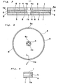
- Fig. 3 shows a first preferred embodiment of a ventilation type optical recording disc according to the present invention.
- a pair of disc substrates 1 in an annular disc shape, in the center of which a round center hole 1a is formed.
- the respective disc substrate 1 is made of an inorganic material such as glass etc., or a plastic material such as polymethyl meta acrylate, polycarbonate, polymethyl pentane, epoxy resin etc..
- An uneven pattern 2 is formed on the one side surface of the disc substrate 1 by a known forming process such as the photopolymerization process, the injection process, the compression process, the injection-compression process etc..
- a recording layer 3 is formed on the one side surface of the disc substrate 1, where the uneven pattern 2 is formed, by a known film forming process such as the spattering process, the vacuum evaporation process, the ion plating process, the plasma evaporation process, the non- electrolysis plating process etc..
- the recording layer 3 is made of a recording material which is suitable to record information on it, such as a recording material used for a heat mode, or an optical thermal magnetic recording material etc.
- An inner spacer 4 and an outer spacer 5 are formed in an annular shape having a predetermined inner diameter and a predetermined outer diameter by an injection forming process, a cutting process, or a punching process etc..
- the spacers 4 and 5 are made by forming a synthetic resin material made of polycarbonate resin, acrylic resin, polymethyl pentane resin, epoxy resin, vinyl chloride resin, or nylon resin etc..
- the spacers 4 and 5 is made by forming a material in a disc shape, made of the aforementioned synthetic resin. Both of the surfaces of the spacers 4 and 5 are flat, and the one side surface of the inner spacer 4 and the outer spacer 5 is coated with a bonding material 8 except for several portions 4a and 5a of the surface, respectively, as shown in Fig. 4.
- a pair of disc substrates 1 are bonded together through the inner spacer 4 and the outer spacer 5, so that each of recording layers 3 of a pair of the disc substrates 1 faces together.
- an inside air gap 6 is formed between the recording layers 3 of both of the disc substrates 1, wherein the inside air gap is isolated from the outside of the optical recording disc.
- Fig. 5 is a partial longitudinal sectional view of the outer spacer 5 on line of I - I' shown in Fig. 4.
- the several portions 5a of the surface of the outer spacer 5, where the bonding material 8 is not coated are formed so that the respective portion 5a extends from the inner rim portion to the outer rim portion of the outer spacer 5, thereby the aforementioned several portions 5a provide several ventilation paths 5a, so that the air in the inside air gap 6 between both of the disc substrates 1 can pass through the ventilation-paths 5a and reversely.
- Fig. 6 shows a second preferred embodiment of the inner spacer 4 and the outer spacer 5 of the optical recording disc according to the present invention.
- the bonding material 8 may be coated on the one side of the inner spacer 4 and the outer spacer 5 with a pattern comprising a number of around ellipse shape, at a predetermined interval between the said around ellipse shapes.
- the portions 4a and 5a of the surface of the spacers 4 and 5, where the bonding material 8 is not coated are formed on the one surface of the spacers 4 and 5, and the portions 4a and 5a of the surface of the spacers 4 and 5 provide a lot of ventilation paths 4a and 5a. Therefore, the ventilation quantity of the optical recording disc shown in Fig.
- the ventilation quantity per a ventilation path 4a or 5a shown in Fig. 6 is less than the ventilation quantity per a ventilation path 4a or 5a shown in Fig. 3.
- Fig. 7 is a partial longitudinal sectional view of ;he outer spacer 5 on line of II - II' shown in Fig. 6.
- the optical recording disc comprises a lot of rentilation paths 5a formed between several pieces of Conding material 8, which are coated between the disc substrate 1 and the outer-spacer 5, wherein the ventilation paths 5a are formed at a predetermined interval. Thereby, the air in the inside air gap 6 and the air in the outside of the optical recording disc can pass through the ventilation paths 5a.
- the width of the ventilation paths 4a and 5a preferably is approximately 5 mm, more particularly in the range of about 3 - 15 mm.
- the thickness of the ventilation paths 4a and 5a preferably is similar to the thickness of the bonding material 8, for example, in the range of 0.5 - 20 ⁇ m.
- the thickness of the ventilation paths 4a and 5a is preferably in the range of 0.5 - 5 ⁇ m in order to prevent an alien substance such as dust etc. from entering the inside air gap 6, which is formed among both of the disc substrates 1, the inner spacer 4 and the outer spacer 5 in the inside portion of the optical recording disc.
- the bonding material 8 may be coated on the surface of the spacers 4 and 5 by person's hand, on the other hand, a mechanical process such as the screen printing process etc. may be used to coat the bonding material 8 uniformly and fast on the surface of the spacers 4 and 5 with the aforementioned pattern comprising a number of around ellipse shape. Either of epoxy resin or ultravioletrays hardening resin may be used as the bonding material 8.
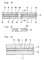
- Fig. 8 shows a third preferred embodiment of the optical recording disc according to the present invention
- Fig. 9 is a longitudinal sectional view of the optical recording disc on line of A - A' shown in Fig. 8.
- the optical recording disc comprises an inner spacer 4 and an outer spacer 5 in an annular shape having a predetermined inner diameter and a predetermined outer diameter, wherein a rough surface 4c is formed on the one side surface of the inner spacer 4 as shown in Fig. 9, with a predetermined roughness taken account into an air conductance, a dust prevention and a process precision to be required.
- the interval between the top points of the rough surface 4c corresponding to the roughness of the rough surface 4c is less than 0.5 ⁇ m, the speed of the ventilation air passing through the ventilation path 4a is less than 2 x10 -10 m 3 /sec and it is difficult to form an uniform rough surface 4c with the said roughness.
- the interval between the top points of the rough surface 4c is more than 3 ⁇ m, the dust whose length is more than 3 ⁇ m can pass through the ventilation path 4a and can adhere to the recording layer 3, thereby it become difficult to record information correctly on the recording layer 3.
- the interval between the top points of the rough surface 4c corresponding to the roughness of the rough surface 4c is preferably in the range of 0.5 - 3 um.
- the inside air gap 6 may be formed between both of the disc substrates 1 with interval members such as the inner spacer 4 and the outer spacer 5, wherein the top and bottom surface of the spacers 4 and 5 are coated with the bonding material 8.
- the ventilation paths 4a are formed between the one side of the disc substrate 1 and the rough surface 4c of the inner spacer 4, where the bonding material 8 is not coated, as shown in Fig. 10, thereby the outside air of the optical recording disc can pass through the ventilation paths 4a into the inside air gap 6 and reversely.
- the dust in the outside air of the optical recording disc is filtered by the ventilation paths 4a and the ventilation paths 4a can prevent the dust in the outside air of the optical recording disc from entering the inside air gap 6, since the width of the respective ventilation path 4a is very small such as approximately 0.5 - 3 ⁇ m. Therefore, it become possible to record information correctly on the recording layer 3 of the optical recording disc.
- Fig. 11 shows a fourth preferred embodiment of the optical recording disc according to the present invention.
- a significant feature is to arrange a pair of disc substrates 11, each comprising two annular projected portions 12 and 13 at the inner rim portion and the outer rim portion of the disc substrate 11.
- the inner annular projected portion 12 is formed as one portion of the disc substrate 11 at the inner rim portion of the disc substrate 11, and the outer annular projected portion 13 is formed as one portion of the disc substrate 11.
- the same reference number is used as the reference number used in Fig. 8 when the member shown in Fig. 11 is similar to the member shown in Fig. 8, respectively.
- a rough surface 12c is formed on at least one side of the surface of the inner projected portion 12.facing the surface of the inner projected portion 12 of another disc substrate 11.
- the interval between the top points of the rough surface 12c corresponding to the roughness of the rough surface 12c is around same as the aforementioned interval shown in the third preferred embodiment of the optical recording disc of Fig. 8, which is in the range of approximately 0.5 - 3 ⁇ m.
- the optical recording disc of the fourth preferred embodiment is made as one body by bonding a pair of disc substrates 11 without the said spacers 4 and 5 shown in the first and second preferred embodiments of Figs. 3 and 8, wherein the surfaces of the inner and outer projected portions 12 and 13, facing the surface of another projected portions 12 and 13, are coated. Ventilation paths 12a are formed between both of the faced surfaces of the inner projected portion 12 of the disc substrate 11 and at the portion where the bonding material 8 is not coated, as shown in Fig. 13.
- the fourth preferred embodiment of the optical recording disc has the same effect as the effect of the third preferred embodiment of the optical recording disc, and the inner and outer spacers 4 and 5 used in the first, second and third preferred embodiment of the optical recording disc can be omitted, since the inner and outer projected portions 12 and 13 are formed at the inner and outer rim portions of both of the disc substrates 11.
- the fourth preferred embodiment of the optical recording disc has the advantage of the less number of the members, of which the optical recording disc consists, and the less number of the making process, than the first, second and third preferred embodiments.
- the bonding material 8 is coated in a belt shape at a predetermined quantity on a predetermined position of the bonding surface of the inner spacer 4, rotating the inner spacer 4, wherein the bonding material 8 is supplied by a dispenser 14. Then, the bonding material 8 is coated, so that the ventilation paths 4a are formed comprising a predetermined width between the spacer 4 and the disc substrate 1 when the bonding material 8 is extended by pressing the inner spacer 4 on the surface of the disc substrate 1.
- the bonding material 8 coated on the surface of the inner spacer 4 is extended by pressing the inner spacer 4 on the surface of the disc substrate 1, so that the one side surface of the inner spacer 4, where the bonding material 8 is coated, faces the surface of the disc substrate 1 where the recording layer 3 is formed, thereby the disc substrate 1 and the inner spacer 4 are bonded as one body.
- the very small ventilation paths 4a whose width is in the range of approximately 0.5 - 3 ⁇ m, are formed in the portion between the surface of disc substrate 1 and the surface of the inner spacer 4 where the bonding material 8 is not coated.
- the outer spacer 5, whose one side surface are coated with the bonding material 8, is bonded on the outer rim portion of the disc substrate 1.
- the bonding material 8 is coated on the one portion of the rough surface 4c, controlling the quantity of the bonding material 8 supplied by the dispenser 14.
- the aspect of the present invention is to arrange the area, where the bonding material 8 is not coated, on the surface of the inner spacer 4, and the other process for coating the bonding material 8 may be used than the aforementioned process for coating the bonding material 8.
- a mask pattern layer 15 in the rectangular disc shape is arranged on the rough surface 4c of the inner spacer 4, wherein the length of the mask pattern layer 15 is around same as the outer diameter of the inner spacer 4 and its width is around same as the required width of the ventilation path 4a.
- the bonding material 8 is coated on the all round surface of the inner spacer 4 and the mask pattern layer 15, the mask pattern layer 15 is taken off. As a result, the area where the bonding material 8 is not coated is formed on the surface of the inner spacer 4.
- the process for_coating the bonding material 8 on the surface of the inner spacer 4, shown in Fig. 16, can be applied to the process for coating on the surface of the outer spacer 5, and the area, where the bonding material 8 is not coated, can be formed on the surface of the outer spacer 5 by the aforementioned process.
- two ventilation paths 4a are formed on the inner spacer 4, however, any number of the ventilation paths 4a may be formed on the surface of the inner spacer 4 by taking account into the air conductance of the inside air gap 6 etc. to be required.
- the bonding material 8 is used as bonding means, however, the other known bonding means may be used, such as the ultrasonic bonding process.
- Fig. 17 is a perspective view of a fifth preferred embodiment of a spacer of the optical recording disc according to the pre.sent invention
- Fig. 18 is an expanded partial perspective view of the A portion shown in Fig. 17.
- a spacer 4 (5) which can be used as the inner spacer 4 and the outer spacer 5, having a predetermined inner diameter and a predetermined outer diameter.
- the spacer 4 (5) for example, is formed in an annular shape by the injection forming process, wherein the spacer 4 (5) is made by forming a synthetic resin material such as polycarbonate resin, acrylic resin, epoxy resin, vinyl chloride resin, or nylon resin etc..
- a projected portion 16 for facing the surface of the disc substrate 1 is formed projecting above the surface of the spacer 4 (5) at the outer rim portion of the surface of the spacer 4 (5), wherein the end portion of the projected portion 16 is positioned at the outer surface of the spacer 4 (5), and the width w of the projected portion 16 in the diameter direction of the spacer 4 (5) is less than the width W of the spacer 4 (5), which is the outer diameter minus the inner diameter.
- the surface 16c of the projected portion 16 is formed roughly.
- the height h and the length 1 of the projected portion 16, and the roughness of the rough surface 16c of the projected portion 16 can be determined taking account into the thickness of the bonding material 8 when the spacer 4 (5) is bonded on the disc substrate 1, an air conductance, a dust prevention and a process precision to-be required. That is, when the spacer 4 (5) is bonded on the disc substrate 1 with the bonding material 8 such as UV resin, epoxy resin and hotmelt etc., the bonding layer, whose thickness is approximately 5 - 20 u m, is generally formed.
- the projected portion 16 of the spacer 4 (5) whose height is approximately 5 - 20 ⁇ m, is formed in order to bond the spacer 4 (5) on the disc substrate 1 so that the surface-of the spacer 4 (5) parallels to the surface of the disc substrate 1.
- the air conductance in the ventilation path 4a (5a) is less than 2 x 10 -10 m3/sec at the air pressure 1 atm, then it become difficult for the outside air of the optical recording disc to pass through the ventilation path 4a (5a) into the inside air gap 6 of the optical recording disc, and it become difficult to form the rough surface 16c uniformly.
- the projected portion 16 of the spacer 4 (5) is formed, so that the interval between the top points of the rough surface 16c preferably is in the range of 0.5 - 3 ⁇ m, and the length 1 of the projected portion 16 in the circumferential direction is preferably in the range of 1 - 10 ⁇ m.
- a ventilation path 4a (5a) is formed by cutting the inner rim portion of the spacer 4a (5a), so that the ventilation path 4a (5a) extends from a 'bonding recess 17 to the inner surface of the spacer 4a (5a).
- the bonding recess 17 is formed in the around cylindrical shape, whose diameter is more than the aforementioned length 1 of the projected portion 16, at the around center portion between the inner rim portion and the outer rim portion of the surface of the spacer 4a (5a) and at the portion which is positioned a little nearer to the projected portion 16 than the said center portion.
- the bonding recess 17 is provided to drop down the bonding material 8, which is coated at the portion where the bonding recess 17 is formed, into-the bonding recess 17, when the bonding material 8 is coated on the surface of the spacer 4 (5) rotating the spacer 4 (5).
- the bonding recess 17 is also provided to prevent the rough surface 16c of the projected portion 16 from being coated with the bonding material 8, when the bonding material 8 is expanded by pressing the spacer 4 (5) on the surface of the disc substrate 1 after being coated.
- the bonding material 8 is coated in a belt shape on the surface of the inner 4 by being supplied continuously with a predetermined quantity by a predetermined quantity by a dispenser 14, wherein there is provided the bonding material 8 which is suitable to bond the inner spacer 4 on the surface of the disc substrate 1.
- the bonding material 8 is expanded by pressing the coated surface of the inner spacer 4 on the surface 1b of the disc substrate 1 where the recording layer 3 is formed, so that the surface 1b faces the rough surface 16c of the projected portion 16 of the spacer 4. Then, the bonding material 8 can not be coated on the rough surface 16c of the projected portion 16, because the bonding material 8, coated at the portion which is positioned a little nearer to the inner surface of the spacer 4 than the inner rim portion of the rough surface 16c of the projected portion 16, is dropped down into the bonding recess 17, and the bonding material 8 can not be extended to the rough surface 16c of the projected surface 16 by pressing the spacer 4 on the surface'of the disc substrate 1.
- very small ventilation paths 4a whose width is in the range of approximately 0.5 - 3 ⁇ m corresponding to the interval between the top points of the rough surface 16c of the projected portion 16, are formed between the surface 1b of the disc substrate 1, where the recording layer 3 is formed, and the rough surface 16c of the projected portion 16 of the spacer 4.
- the bonding material 8 is extended so that the thickness of the bonding material 8 is 5 - 20 um, and the geometric level of the rough surface 16a of the projected portion 16 become around equal to the level of the surface of the bonding material 8. Therefore, an excessive interval between the surface 1b of the disc substrate 1 and the rough surface 1 6c of the projected portion 16 cannot be formed, moreover, the inner spacer 4 cannot be arranged on the condition that the inner spacer slants to the disc substrate 1.
- an outer spacer 5 in an annular shape is bonded on the outer rim-portion of the surface 1b of the disc substrate 1, on the surface 1b of which the recording layer 3 is formed, wherein the outer spacer does not comprising a projected portion 16.
- another second disc substrate 1 is bonded on the opposite side surface to the side surface of the inner and outer surface 4 and 5, where the first disc substrate 1 is formed, so that the recording layer 3 of the first disc substrate 1 faces the recording layer 3 of the second disc substrate 1. Then, the process for making the optical recording disc is completed.
- the outside air of the optical recording disc can pass through the ventilation paths 4a into the inside air gap 6 of the optical recording disc, because the ventilation paths 4a are formed.between the surface 1b of the disc substrate 1 and the rough surface 16c of the projected portion 16 of the inner spacer 4.
- the ventilation paths 4a can prevent the dust in the outside air of the optical recording disc from entering the inside air gap 6 of the optical recording disc, because the width of the respective ventilation path 4a, through which the outside air passes, is very small and in the range of approximately 0.5 - 3 ⁇ m, and the outside dust is filtered by the ventilation path 4a.
- the projected portion 16 is formed only on the surface of the inner spacer 4, however, the projected portion 16 may be formed on the surface of the outer spacer 5. The projected portion 16 may be formed on the surface of both of the inner and outer spacers 4 and 5.
- only one projected portion 16 is formed on the surface of the inner spacer 4, however, any number of the projected portion 16 may be formed on the surface of the inner spacer 4 or/and the outer spacer 5.
- a plurality of the projected portion 16 can make the two disc substrates 1 and spacers 4 and 5 bond together more stably than only one projected portion 16, and they can facilitate bonding the two disc substrates 1 and the spacers 4 and 5 together.
- the projected portion 16 is formed on the outer rim portion of the surface of the spacer 4 (5) and the bonding recess 17 is formed in the cylindrical shape at the inside of the projected portion 16, however, the projected portion 16 may be formed on any position of the surface of the spacer 4 (5) and the boding recess 17 may be formed in any shape, whose diameter or width is within the width of the spacer 4 (5) corresponding to the outer diameter minus the inner diameter, and on any position of the surface of the spacer 4 (5). For example, as shown in Fig.
- the projected portion 16 may be formed on the inner rim portion of the surface of the spacer 4 (5), and the ventilation path 4a (5a) may be formed so that the ventilation path 4a (5a) extends from the bonding recess 17 to the outer surface of the spacer 4 (5).
- The.bonding recess 17 may be formed in an around rectangular shape on the surface of the spacer 4 (5).
- the projected portion 16, the ventilation path 4a (5a) and the bonding recess 17 are formed on the surface of the spacer 4 (5), however, the projected portion 16, the ventilation path 4a . (5a) and the bonding recess 17 may be formed on the surface of the disc substrate 1.
- the bonding recess 17 is formed at the nearer position on the surface of the spacer 4 (5) to the projected portion 16, however, and the bonding recess 17 is provided to prevent the bonding material 8 from being coated on the surface of the spacer 4 (5) near the surface'of the projected portion 16.
- the bonding recess . 17 may be omitted when the width of the ventilation path 4a (5a) is large enough to make the bonding material 8 drop down, that is, to prevent the bonding material 8 from being coated on the aforementioned surface of the spacer 4 (5) not to be coated.
- the disc substrate 1 is separate from the inner and outer spacers 4 and 5, and the spacers 4 and 5 are bonded on the surface of the disc substrate 1, however, projected portions in an annular shape may be formed on the inner rim portion and the outer rim portion of the surface of the disc substrates 1, instead of the inner spacer 4 and the outer spacer 5.
Landscapes
- Optical Record Carriers And Manufacture Thereof (AREA)
Applications Claiming Priority (6)
| Application Number | Priority Date | Filing Date | Title |
|---|---|---|---|
| JP60054135A JP2590304B2 (ja) | 1985-03-20 | 1985-03-20 | 情報記録用デイスク |
| JP54135/85 | 1985-03-20 | ||
| JP257856/85 | 1985-11-19 | ||
| JP60257856A JPS62119749A (ja) | 1985-11-19 | 1985-11-19 | 通気型光デイスク |
| JP61021195A JPS62180539A (ja) | 1986-02-04 | 1986-02-04 | 通気型光情報記録デイスク |
| JP21195/86 | 1986-02-04 |
Publications (3)
| Publication Number | Publication Date |
|---|---|
| EP0195720A2 true EP0195720A2 (fr) | 1986-09-24 |
| EP0195720A3 EP0195720A3 (en) | 1988-04-06 |
| EP0195720B1 EP0195720B1 (fr) | 1992-02-05 |
Family
ID=27283329
Family Applications (1)
| Application Number | Title | Priority Date | Filing Date |
|---|---|---|---|
| EP19860400577 Expired EP0195720B1 (fr) | 1985-03-20 | 1986-03-19 | Disposition de ventilation pour disque optique d'enregistrement |
Country Status (1)
| Country | Link |
|---|---|
| EP (1) | EP0195720B1 (fr) |
Cited By (6)
| Publication number | Priority date | Publication date | Assignee | Title |
|---|---|---|---|---|
| WO1987002934A1 (fr) * | 1985-11-18 | 1987-05-21 | Eastman Kodak Company | Estampage de supports d'enregistrement optique |
| DE3736879A1 (de) * | 1986-10-30 | 1988-05-11 | Pioneer Electronic Corp | Optische informationsaufzeichnungsplatte |
| EP0268352A1 (fr) * | 1986-08-28 | 1988-05-25 | Canon Kabushiki Kaisha | Procédé pour fabriquer un moyen d'enregistrement optique |
| EP0301832A1 (fr) * | 1987-07-27 | 1989-02-01 | Mitsui Petrochemical Industries, Ltd. | Procédé pour produire des disques pour enregistrement d'information |
| US5263016A (en) * | 1987-07-27 | 1993-11-16 | Mitsui Petrochemical Industries, Ltd. | Information recording discs |
| WO1999039340A1 (fr) * | 1998-01-30 | 1999-08-05 | Optidisc International Limited | Appareil de protection de support de stockage de donnees optiques |
Citations (3)
| Publication number | Priority date | Publication date | Assignee | Title |
|---|---|---|---|---|
| US4074282A (en) | 1976-05-13 | 1978-02-14 | North American Philips Corporation | Radiation-sensitive record with protected sensitive surface |
| JPS54106204A (en) | 1978-02-07 | 1979-08-21 | Matsushita Electric Ind Co Ltd | Information recording disc of transparent type |
| JPS59171049A (ja) | 1983-03-18 | 1984-09-27 | Hitachi Ltd | 光デイスク |
Family Cites Families (3)
| Publication number | Priority date | Publication date | Assignee | Title |
|---|---|---|---|---|
| US4319252A (en) * | 1980-07-21 | 1982-03-09 | Drexler Technology Corporation | Optical data storage and recording medium having a replaceable protective coverplate |
| JPS58130451A (ja) * | 1982-01-29 | 1983-08-03 | Toshiba Corp | 情報記憶媒体 |
| JPS5987636A (ja) * | 1982-11-10 | 1984-05-21 | Toshiba Corp | 情報記憶媒体 |
-
1986
- 1986-03-19 EP EP19860400577 patent/EP0195720B1/fr not_active Expired
Patent Citations (3)
| Publication number | Priority date | Publication date | Assignee | Title |
|---|---|---|---|---|
| US4074282A (en) | 1976-05-13 | 1978-02-14 | North American Philips Corporation | Radiation-sensitive record with protected sensitive surface |
| JPS54106204A (en) | 1978-02-07 | 1979-08-21 | Matsushita Electric Ind Co Ltd | Information recording disc of transparent type |
| JPS59171049A (ja) | 1983-03-18 | 1984-09-27 | Hitachi Ltd | 光デイスク |
Cited By (7)
| Publication number | Priority date | Publication date | Assignee | Title |
|---|---|---|---|---|
| WO1987002934A1 (fr) * | 1985-11-18 | 1987-05-21 | Eastman Kodak Company | Estampage de supports d'enregistrement optique |
| EP0268352A1 (fr) * | 1986-08-28 | 1988-05-25 | Canon Kabushiki Kaisha | Procédé pour fabriquer un moyen d'enregistrement optique |
| US4892606A (en) * | 1986-08-28 | 1990-01-09 | Canon Kabushiki Kaisha | Optical recording medium having space therein and method of manufacturing the same |
| DE3736879A1 (de) * | 1986-10-30 | 1988-05-11 | Pioneer Electronic Corp | Optische informationsaufzeichnungsplatte |
| EP0301832A1 (fr) * | 1987-07-27 | 1989-02-01 | Mitsui Petrochemical Industries, Ltd. | Procédé pour produire des disques pour enregistrement d'information |
| US5263016A (en) * | 1987-07-27 | 1993-11-16 | Mitsui Petrochemical Industries, Ltd. | Information recording discs |
| WO1999039340A1 (fr) * | 1998-01-30 | 1999-08-05 | Optidisc International Limited | Appareil de protection de support de stockage de donnees optiques |
Also Published As
| Publication number | Publication date |
|---|---|
| EP0195720A3 (en) | 1988-04-06 |
| EP0195720B1 (fr) | 1992-02-05 |
Similar Documents
| Publication | Publication Date | Title |
|---|---|---|
| US4720826A (en) | Ventilation arrangement for use in an optical recording disc | |
| US4699268A (en) | Magnetic recording disk cartridge | |
| US20020043328A1 (en) | Method of production of multilayer optical recording medium | |
| EP0195720B1 (fr) | Disposition de ventilation pour disque optique d'enregistrement | |
| US4800458A (en) | Recording sheet bonded to a substrate in a magnetic disk | |
| JPS59171049A (ja) | 光デイスク | |
| EP1211684B1 (fr) | Procédé de fabrication d'une cartouche de disque magnétique | |
| US4960268A (en) | Spacer holder arrangement | |
| KR880009347A (ko) | 정보기록매체 | |
| US4779160A (en) | Magnetic recording disk | |
| JPS6177163A (ja) | 磁気ヘツド | |
| JPH0344838A (ja) | 光ディスク | |
| JPS62180539A (ja) | 通気型光情報記録デイスク | |
| JPS63164043A (ja) | 光デイスクの形成方法 | |
| JP2702497B2 (ja) | 光情報記録媒体 | |
| JPS62298949A (ja) | 光記録媒体用基板の製造のための装置 | |
| JP3098816B2 (ja) | 光ディスク記録媒体 | |
| JPS61236044A (ja) | 円盤状記録担体 | |
| JPS5814342A (ja) | 光記憶素子の製造方法 | |
| JPH0457233A (ja) | 光ディスク用基板 | |
| KR100727912B1 (ko) | 디스크 결합을 위한 지지기판 | |
| JPH0378105A (ja) | マルチトラツク磁気ヘッド | |
| JPH06124482A (ja) | 光記録媒体 | |
| JPH02152044A (ja) | 光記録媒体の製造方法 | |
| JPS6242363A (ja) | 磁気デイスク装置 |
Legal Events
| Date | Code | Title | Description |
|---|---|---|---|
| PUAI | Public reference made under article 153(3) epc to a published international application that has entered the european phase |
Free format text: ORIGINAL CODE: 0009012 |
|
| AK | Designated contracting states |
Kind code of ref document: A2 Designated state(s): FR NL |
|
| PUAL | Search report despatched |
Free format text: ORIGINAL CODE: 0009013 |
|
| AK | Designated contracting states |
Kind code of ref document: A3 Designated state(s): FR NL |
|
| 17P | Request for examination filed |
Effective date: 19880725 |
|
| 17Q | First examination report despatched |
Effective date: 19891121 |
|
| GRAA | (expected) grant |
Free format text: ORIGINAL CODE: 0009210 |
|
| AK | Designated contracting states |
Kind code of ref document: B1 Designated state(s): FR NL |
|
| ET | Fr: translation filed | ||
| PLBE | No opposition filed within time limit |
Free format text: ORIGINAL CODE: 0009261 |
|
| STAA | Information on the status of an ep patent application or granted ep patent |
Free format text: STATUS: NO OPPOSITION FILED WITHIN TIME LIMIT |
|
| 26N | No opposition filed | ||
| PGFP | Annual fee paid to national office [announced via postgrant information from national office to epo] |
Ref country code: FR Payment date: 20030310 Year of fee payment: 18 |
|
| PGFP | Annual fee paid to national office [announced via postgrant information from national office to epo] |
Ref country code: NL Payment date: 20030327 Year of fee payment: 18 |
|
| PG25 | Lapsed in a contracting state [announced via postgrant information from national office to epo] |
Ref country code: NL Free format text: LAPSE BECAUSE OF NON-PAYMENT OF DUE FEES Effective date: 20041001 |
|
| PG25 | Lapsed in a contracting state [announced via postgrant information from national office to epo] |
Ref country code: FR Free format text: LAPSE BECAUSE OF NON-PAYMENT OF DUE FEES Effective date: 20041130 |
|
| NLV4 | Nl: lapsed or anulled due to non-payment of the annual fee |
Effective date: 20041001 |
|
| REG | Reference to a national code |
Ref country code: FR Ref legal event code: ST |