EP0195759A2 - Extrémité de contact pour une électrode de soudage - Google Patents
Extrémité de contact pour une électrode de soudage Download PDFInfo
- Publication number
- EP0195759A2 EP0195759A2 EP86850044A EP86850044A EP0195759A2 EP 0195759 A2 EP0195759 A2 EP 0195759A2 EP 86850044 A EP86850044 A EP 86850044A EP 86850044 A EP86850044 A EP 86850044A EP 0195759 A2 EP0195759 A2 EP 0195759A2
- Authority
- EP
- European Patent Office
- Prior art keywords
- contact
- contact tip
- electrode
- axis
- tip according
- Prior art date
- Legal status (The legal status is an assumption and is not a legal conclusion. Google has not performed a legal analysis and makes no representation as to the accuracy of the status listed.)
- Granted
Links
Images

Classifications
-
- B—PERFORMING OPERATIONS; TRANSPORTING
- B23—MACHINE TOOLS; METAL-WORKING NOT OTHERWISE PROVIDED FOR
- B23K—SOLDERING OR UNSOLDERING; WELDING; CLADDING OR PLATING BY SOLDERING OR WELDING; CUTTING BY APPLYING HEAT LOCALLY, e.g. FLAME CUTTING; WORKING BY LASER BEAM
- B23K9/00—Arc welding or cutting
- B23K9/24—Features related to electrodes
- B23K9/28—Supporting devices for electrodes
-
- B—PERFORMING OPERATIONS; TRANSPORTING
- B23—MACHINE TOOLS; METAL-WORKING NOT OTHERWISE PROVIDED FOR
- B23K—SOLDERING OR UNSOLDERING; WELDING; CLADDING OR PLATING BY SOLDERING OR WELDING; CUTTING BY APPLYING HEAT LOCALLY, e.g. FLAME CUTTING; WORKING BY LASER BEAM
- B23K9/00—Arc welding or cutting
- B23K9/12—Automatic feeding or moving of electrodes or work for spot or seam welding or cutting
- B23K9/122—Devices for guiding electrodes, e.g. guide tubes
- B23K9/123—Serving also as contacting devices supplying welding current to an electrode
Definitions
- the invention relates to a contact tip for supplying the current to a welding electrode.
- Such contact tips are commonly found in welding equipment such as e.g. Welding torches.
- the welding current is transferred to the welding electrode, for example a solid wire electrode or a powder-filled tube electrode, which is advanced through the contact tip.
- Known contact tips have the shape of a tube, the inside diameter of which is slightly larger than the diameter of the electrode. During its passage through this contact tube, the electrode slides along the tube wall and thereby creates the desired contact for the transfer of the welding current from the contact tube to the electrode.
- Contact tubes of this type can be bent somewhat in order to improve the contact between the contact tube and the electrode. However, the position of the contact between the contact tube and the electrode is not fixed. The result of this is that the length of the electrode section through which the welding current flows changes constantly between its tip and the contact. Because of the changing resistance of the current-carrying electrode section, the energy supply to the welding point also changes, which adversely affects the welding quality.
- US Pat. No. 3,112,393 describes a contact tube with a helical passage for the electrode. There is uniform electrical contact between the electrode and the inner wall of the contact tube over the entire length of the contact tube.
- the manufacture of such contact tubes, which starts from a tube with a relatively small inner diameter, is complicated and therefore also expensive.
- the welding electrodes are often covered with a protective coating to protect them against oxidation and corrosion.
- the electrodes are also exposed to dust or other contamination.
- the Abriysb electrode is dragged along with it from the electrode guide. This material accumulates in the narrow contact tube and is packed there to form a dense mass, which interferes with the desired, even feed of the electrode.
- the present invention has for its object to provide a contact tip with which the aforementioned disadvantages are avoided.
- the contact tip is rod-shaped and provided on the rod with a helical contact surface with respect to the axis of the contact tip.
- Contact tips according to the invention are simple and inexpensive to manufacture. A particular advantage is the all-round accessibility of the contact area.
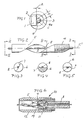
- the contact tip in Fig. 1 consists of a rod 1 with a rectangular cross section, which is wound at least once around the axis.
- the surface 2 closest to the axis and the other side surfaces of the rod form screw surfaces.
- the axis C is located outside the rod 1 at a distance A from the surface 2.
- An electrode 3 is in contact with the surface 2. Without the electrode, the contact tip has a straight cylindrical passage 4, which is indicated by the dashed circle 4a with the Diameter 2A is specified.
- the diameter D of the electrode is thus larger than the diameter of the passage 4.
- the electrode must therefore theoretically lie against the helix of the surface 2 which is closest to the axis C when it is advanced along the surface 2. Because of the geometrical imperfections of the electrode and the contact tip, the electrode touches the rod in a narrow band-shaped contact surface of the rod, which comprises said helix and extends axially along the length of the rod.
- the bending of the electrode advanced along the contact tip depends partly on the position of the axis C with respect to the rod, partly on the electrode diameter D, partly on the pitch of the screw surface and not least on the geometric imperfections of the contact tip and the electrode.
- the electrode is usually not perfectly straight when it is fed to the contact tip.
- Positive values of A mean that the axis C is located outside the rod, while negative values of A mean that the axis C penetrates the rod.
- the diameter of the passage 4 is the same as that of the electrode. If the electrode advanced along the contact tip is completely straight, the electrode in contact tips, for which the condition 0.5D e A ⁇ 0.6D applies, will only touch the contact surface of the contact tip by chance. It has been found that due to the imperfections mentioned above, a distance of up to 0.6D can be chosen and nevertheless a reliable contact between the electrode and the contact tip is established. In particular, thicker electrodes with diameters of a few millimeters glide smoothly on the helical contact surface. A suitable value of A can be determined by experiments.
- A is preferably in the range 0 A A * 0.5D. If the value of A is negative, the electrode is deformed considerably by the helical contact surface during its advance, which results in a very high contact pressure. This leads to very rapid wear of the contact tip, especially when using thick electrodes. Such wear can be accepted if a particularly low contact resistance between the electrode and the contact tip is desired. The lower the contact resistance, the lower the contact losses that affect the heating of the contact tip. If the value of A is not chosen to be greater than 0.5D, electrodes that are fed straight to the contact tip will establish a perfect contact with it.
- a lower deformation of the electrode along the contact surface results in a lower contact pressure, but also less wear. It has been found that the contact tip is optimally used if the distance A satisfies the following conditions:
- the electrode tip In order to increase the service life of the contact tip, it is expedient to provide the electrode tip with a layer of wear-resistant, conductive material, for example nickel or nickel alloy. Such a layer can be applied to the contact surface without difficulty by electroplating or another method, since the surface is accessible from all sides.
- pitch of the helix Another dimension of the helix that has a great influence on the wear of the contact tip is the pitch of the helix. This should preferably not be less than 10D. The smaller the slope and the smaller the distance A, the more the electrode is bent as it passes through the contact tip. This increases the feed resistance for the electrode and thus the wear of the contact tip.
- the length of the contact tip corresponds to at least one complete rotation of the helix around the axis.
- the electrode is bent in all directions as it passes through the contact tip. As a result, the electrode is directed in the contact tip and it always leaves it in a certain direction, which, for example, makes the precise adjustment of the welding torch with respect to the workpiece much easier.
- the contact tip in Fig. 2 consists of a rod 5 which is helically wound around the axis C '.
- the rod has a substantially semi-cylindrical shape with an outer cylindrical surface 6 and a somewhat concave surface 7.
- a welding electrode 8 is advanced along the concave surface 7 and is in contact with it.
- the contact tip in Figure 2 is dimensioned such that the distance between the helix closest to the axis C 'is greater than zero.
- the axis C ' is therefore outside the rod.
- the distance A is smaller than the radius of the electrode, which is thus forced to carry out a helical feed movement during the passage of the contact tip, as can be seen in FIGS. 2 to 5.
- Dust and other material that is carried from the electrode through the electrode conductor to the contact tip falls out of the contact tip and does not interfere with the advancement of the electrode in the area of the contact tip.
- the contact tip is provided at its rear end with a thread 9 with which it is fastened in a corresponding holder 11 of a welding torch 10 provided with a gas nozzle 12 (FIG. 6).
- a slightly modified contact tip in FIG. 7 consists of a rod 13 which is provided with a V-shaped, helical groove 14 for an electrode 16.
- the groove has a rounded groove base 15, the radius of curvature of which is greater than the radius of the electrode.
- the electrode slides along the bottom of the groove, as shown in Figs. 9 and 10.
- the contact resistance is small and the heating of the contact tip is so low that welding spatter cannot get stuck on the moderately warm contact tip. If, however, with large Welding spatter losses must be expected, it may be advantageous to attach a mouthpiece 17 to the front of the contact tip, which essentially protects the contact tips from the welding spatter and also ensures that the electrode emerges from the mouthpiece in a certain direction.
- the contact tip in FIGS. 11 and 12, which corresponds to the contact tip in FIG. 2, is surrounded by a sleeve 18.
- the flow of the protective gas surrounding the contact tip - as indicated by the arrows 19 in Fig. 6 - can be disturbed by the helical surface of the contact tip. Since the flow rate of the gas through the mouthpiece is relatively slow, such disturbances can normally be neglected because they occur only to a very small extent.
- the sleeve is therefore only to be used if there are particularly high demands on undisturbed gas protection. Unless the contact tip to be provided with a wear layer, it is introduced to e-g, before the tip is inserted into the sleeve.
- the contact tips according to the invention can be produced in various ways. It is e.g. this is obvious by turning an originally straight rod around an axis that is at a distance A from the surface of the rod. However, certain problems can arise if the material, which is usually a hard copper alloy, is difficult to deform in this way. However, it is also possible to produce such contact tips by extrusion or continuous casting. Furthermore, it is conceivable to process appropriately shaped rod-shaped starting material in such a way that the desired helical contact surface is obtained. For example, contact tips according to FIG. 7 can be produced without the additional mouthpiece 17 in a similar manner to twist drills.
Landscapes
- Engineering & Computer Science (AREA)
- Plasma & Fusion (AREA)
- Mechanical Engineering (AREA)
- Physics & Mathematics (AREA)
- Arc Welding In General (AREA)
- Contacts (AREA)
- Resistance Welding (AREA)
- Manufacture Of Switches (AREA)
- Motor Or Generator Current Collectors (AREA)
- Connections Effected By Soldering, Adhesion, Or Permanent Deformation (AREA)
- Manufacturing Of Electrical Connectors (AREA)
- Ultra Sonic Daignosis Equipment (AREA)
- Detergent Compositions (AREA)
- Saccharide Compounds (AREA)
Priority Applications (1)
| Application Number | Priority Date | Filing Date | Title |
|---|---|---|---|
| AT86850044T ATE51554T1 (de) | 1985-02-15 | 1986-02-12 | Kontaktspitze fuer schweisselektrode. |
Applications Claiming Priority (2)
| Application Number | Priority Date | Filing Date | Title |
|---|---|---|---|
| SE8500714A SE8500714L (sv) | 1985-02-15 | 1985-02-15 | Kontaktmunstycke med en skruvlinjeformig passage for en smeltbar svetstrad |
| SE8500714 | 1985-02-15 |
Publications (3)
| Publication Number | Publication Date |
|---|---|
| EP0195759A2 true EP0195759A2 (fr) | 1986-09-24 |
| EP0195759A3 EP0195759A3 (en) | 1988-01-20 |
| EP0195759B1 EP0195759B1 (fr) | 1990-04-04 |
Family
ID=20359130
Family Applications (1)
| Application Number | Title | Priority Date | Filing Date |
|---|---|---|---|
| EP86850044A Expired - Lifetime EP0195759B1 (fr) | 1985-02-15 | 1986-02-12 | Extrémité de contact pour une électrode de soudage |
Country Status (14)
| Country | Link |
|---|---|
| US (1) | US4733052A (fr) |
| EP (1) | EP0195759B1 (fr) |
| JP (1) | JPS61235081A (fr) |
| AT (1) | ATE51554T1 (fr) |
| AU (1) | AU578795B2 (fr) |
| BR (1) | BR8600612A (fr) |
| CA (1) | CA1247707A (fr) |
| DE (2) | DE8603602U1 (fr) |
| DK (1) | DK161572C (fr) |
| ES (1) | ES8704104A1 (fr) |
| FI (1) | FI81286C (fr) |
| IE (1) | IE57194B1 (fr) |
| NO (1) | NO167718C (fr) |
| SE (1) | SE8500714L (fr) |
Cited By (3)
| Publication number | Priority date | Publication date | Assignee | Title |
|---|---|---|---|---|
| WO1988006072A1 (fr) * | 1987-02-23 | 1988-08-25 | Ossi Hiltunen | Injecteur de courant pour chalumeau de soudage du type mig et mag |
| US11938542B2 (en) | 2018-12-20 | 2024-03-26 | Messer Se & Co. Kgaa | Method for finishing a workpiece made by additive manufacturing |
| US12091737B2 (en) | 2018-10-02 | 2024-09-17 | Messer Se & Co. Kgaa | Method for improved current contacting when welding using a current-carrying wire electrode |
Families Citing this family (47)
| Publication number | Priority date | Publication date | Assignee | Title |
|---|---|---|---|---|
| SE467531B (sv) * | 1989-03-07 | 1992-08-03 | Esab Ab | Kontaktmunstycke |
| US5319175A (en) * | 1992-12-23 | 1994-06-07 | Basix Industries Ltd. | Apparatus for transferring electrical current to and from a moving wire |
| US5384444A (en) * | 1992-12-23 | 1995-01-24 | Basix Technologies Ltd. | Sleeve forming wire passageway around pickup |
| US5380973A (en) * | 1992-12-23 | 1995-01-10 | Basix Technologies Ltd. | Current pickup indexing apparatus |
| US5430268A (en) * | 1992-12-23 | 1995-07-04 | Basix Technologies Ltd. | Method and apparatus for adjusting and replacing EDM components from the guide assembly working end |
| DE4404802C1 (de) * | 1994-02-16 | 1995-08-03 | Zentrum Fuer Material Und Umwe | Kontaktrohr für Lichtbogenschweißbrenner |
| WO1998042472A1 (fr) * | 1997-03-21 | 1998-10-01 | Warner Chemical Co., Ltd. | Extremite de tete de soudage et tete de soudage |
| DE19737934C1 (de) * | 1997-08-30 | 1998-12-10 | Binzel Alexander Gmbh Co Kg | Stromdüse |
| US6011237A (en) * | 1999-06-17 | 2000-01-04 | Yang; Daniel | Locking electrode tip for resistance spot-welding |
| US6559416B1 (en) | 2000-08-25 | 2003-05-06 | Illinois Tool Works | Alternate current path for mig gun |
| US6689988B2 (en) * | 2001-09-28 | 2004-02-10 | Illinois Tool Works Inc. | Welding gun having a plated tip and method for making same |
| US7271366B2 (en) * | 2004-04-05 | 2007-09-18 | M.K. Products, Inc. | Welding gun contact tip |
| GB0418899D0 (en) * | 2004-08-24 | 2004-09-29 | Saipem Spa | Welding torch |
| USD535166S1 (en) | 2005-04-04 | 2007-01-16 | M.K. Products, Inc. | Welding gun |
| US7244909B2 (en) * | 2005-04-04 | 2007-07-17 | M.K. Products, Inc. | Welding gun |
| AT503468B1 (de) * | 2006-04-04 | 2008-04-15 | Fronius Int Gmbh | Verfahren zur reinigung eines kontaktrohres eines schweissbrenners |
| DE102007041711A1 (de) | 2007-05-07 | 2008-11-13 | Eiche, Daniel | Stromleitungsdüse für das Lichtbogenschweissen mit drahtförmigen Elektroden |
| US8357877B2 (en) * | 2009-06-11 | 2013-01-22 | Illinois Tool Works Inc. | Front consumables for pulse GMAW torches |
| US8383987B2 (en) * | 2009-09-25 | 2013-02-26 | Illinois Tool Works Inc. | Welding contact tips for pulse applications |
| US9782852B2 (en) | 2010-07-16 | 2017-10-10 | Hypertherm, Inc. | Plasma torch with LCD display with settings adjustment and fault diagnosis |
| US10486260B2 (en) * | 2012-04-04 | 2019-11-26 | Hypertherm, Inc. | Systems, methods, and devices for transmitting information to thermal processing systems |
| US10455682B2 (en) | 2012-04-04 | 2019-10-22 | Hypertherm, Inc. | Optimization and control of material processing using a thermal processing torch |
| EP2640545B1 (fr) | 2010-11-19 | 2020-05-06 | Cooper, Edward L. | Combinaison d'une buse contact et d'un fil de soudage, et methode de soudage metallique a l'arc sous gaz sur une surface de soudage |
| US9193005B2 (en) | 2011-11-02 | 2015-11-24 | Illinois Tool Works Inc. | Contact tip with contoured bore |
| PL2776200T3 (pl) | 2011-11-13 | 2017-04-28 | Victor Equipment Company | Urządzenia do spawania łukowego z urządzeniem centrującym z rurką przewodu i wykładziną przewodu |
| US20150332071A1 (en) | 2012-04-04 | 2015-11-19 | Hypertherm, Inc. | Configuring Signal Devices in Thermal Processing Systems |
| US9672460B2 (en) | 2012-04-04 | 2017-06-06 | Hypertherm, Inc. | Configuring signal devices in thermal processing systems |
| US11783138B2 (en) * | 2012-04-04 | 2023-10-10 | Hypertherm, Inc. | Configuring signal devices in thermal processing systems |
| US9737954B2 (en) | 2012-04-04 | 2017-08-22 | Hypertherm, Inc. | Automatically sensing consumable components in thermal processing systems |
| US9395715B2 (en) | 2012-04-04 | 2016-07-19 | Hypertherm, Inc. | Identifying components in a material processing system |
| US9643273B2 (en) | 2013-10-14 | 2017-05-09 | Hypertherm, Inc. | Systems and methods for configuring a cutting or welding delivery device |
| US11684995B2 (en) | 2013-11-13 | 2023-06-27 | Hypertherm, Inc. | Cost effective cartridge for a plasma arc torch |
| US11432393B2 (en) | 2013-11-13 | 2022-08-30 | Hypertherm, Inc. | Cost effective cartridge for a plasma arc torch |
| US9981335B2 (en) | 2013-11-13 | 2018-05-29 | Hypertherm, Inc. | Consumable cartridge for a plasma arc cutting system |
| US11278983B2 (en) | 2013-11-13 | 2022-03-22 | Hypertherm, Inc. | Consumable cartridge for a plasma arc cutting system |
| US10456855B2 (en) | 2013-11-13 | 2019-10-29 | Hypertherm, Inc. | Consumable cartridge for a plasma arc cutting system |
| US12275082B2 (en) | 2013-11-13 | 2025-04-15 | Hypertherm, Inc. | Consumable cartridge for a plasma arc cutting system |
| US10582605B2 (en) | 2014-08-12 | 2020-03-03 | Hypertherm, Inc. | Cost effective cartridge for a plasma arc torch |
| US9993934B2 (en) | 2014-03-07 | 2018-06-12 | Hyperthem, Inc. | Liquid pressurization pump and systems with data storage |
| US12521905B2 (en) | 2014-03-07 | 2026-01-13 | Hypertherm, Inc. | Liquid pressurization pump and systems with data storage |
| US10786924B2 (en) | 2014-03-07 | 2020-09-29 | Hypertherm, Inc. | Waterjet cutting head temperature sensor |
| US20150269603A1 (en) | 2014-03-19 | 2015-09-24 | Hypertherm, Inc. | Methods for Developing Customer Loyalty Programs and Related Systems and Devices |
| AU2016301372B2 (en) | 2015-08-04 | 2021-07-29 | Hypertherm, Inc. | Cartridge for a liquid-cooled plasma ARC torch |
| US10583514B2 (en) * | 2015-09-18 | 2020-03-10 | Illinois Tool Works Inc. | Contact tip rotary lock of a welding torch |
| US10773332B2 (en) * | 2015-09-18 | 2020-09-15 | Illinois Tool Works Inc. | Contact tip and receiving assembly of a welding torch |
| US10413991B2 (en) | 2015-12-29 | 2019-09-17 | Hypertherm, Inc. | Supplying pressurized gas to plasma arc torch consumables and related systems and methods |
| KR102518327B1 (ko) | 2017-02-09 | 2023-04-04 | 하이퍼썸, 인크. | 플라즈마 아크 토치 카트리지를 위한 선회 링 및 콘택 요소 |
Family Cites Families (10)
| Publication number | Priority date | Publication date | Assignee | Title |
|---|---|---|---|---|
| US1953915A (en) * | 1931-10-22 | 1934-04-03 | Una Welding & Bonding Company | Welding rod conduit |
| US1959180A (en) * | 1933-09-19 | 1934-05-15 | Gen Electric | Electrode nozzle |
| US3108180A (en) * | 1961-02-07 | 1963-10-22 | Pullmax Ab | Welding electrode mouthpiece |
| US3142746A (en) * | 1961-07-28 | 1964-07-28 | Smith Corp A O | Consumable electrode arc welding apparatus |
| US3112393A (en) * | 1961-09-13 | 1963-11-26 | Union Carbide Corp | Helical welding contactor tube |
| DE1197528B (de) * | 1961-09-13 | 1965-07-29 | Union Carbide Corp | Kontaktfuehrungsrohr fuer Schutzgas-Lichtbogenschweissbrenner |
| DE1540811A1 (de) * | 1964-06-26 | 1971-10-07 | Heer & Co | Vorrichtung zur Fuehrung und zur Stromueberlagerung eines abschmelzenden Zusatzdrahtes beim Metall-Inert-Gas-Schutzgasschweissverfahren |
| FR1476227A (fr) * | 1966-04-15 | 1967-04-07 | Philips Nv | Organe de contact pour l'amenée de courant à un fil de soudure |
| SE382003B (sv) * | 1974-05-07 | 1976-01-12 | Elektriska Svetsnings Ab | Kontaktdon for tillforsel av svetsstrom till en smeltbar elektrod |
| SU1007872A1 (ru) * | 1980-04-04 | 1983-03-30 | Запорожский Проектно-Конструкторский И Технологический Институт | Контактный наконечник к горелкам дл электродуговой сварки плав щимс электродом |
-
1985
- 1985-02-15 SE SE8500714A patent/SE8500714L/ not_active IP Right Cessation
-
1986
- 1986-02-07 AU AU53309/86A patent/AU578795B2/en not_active Ceased
- 1986-02-10 JP JP61026047A patent/JPS61235081A/ja active Granted
- 1986-02-11 FI FI860625A patent/FI81286C/fi not_active IP Right Cessation
- 1986-02-12 AT AT86850044T patent/ATE51554T1/de not_active IP Right Cessation
- 1986-02-12 EP EP86850044A patent/EP0195759B1/fr not_active Expired - Lifetime
- 1986-02-12 DE DE8603602U patent/DE8603602U1/de not_active Expired
- 1986-02-12 DE DE8686850044T patent/DE3670019D1/de not_active Expired - Lifetime
- 1986-02-13 BR BR8600612A patent/BR8600612A/pt unknown
- 1986-02-13 NO NO860537A patent/NO167718C/no unknown
- 1986-02-14 CA CA000501854A patent/CA1247707A/fr not_active Expired
- 1986-02-14 ES ES552025A patent/ES8704104A1/es not_active Expired
- 1986-02-14 IE IE415/86A patent/IE57194B1/en not_active IP Right Cessation
- 1986-02-14 DK DK071886A patent/DK161572C/da not_active IP Right Cessation
- 1986-02-14 US US06/829,828 patent/US4733052A/en not_active Expired - Fee Related
Cited By (3)
| Publication number | Priority date | Publication date | Assignee | Title |
|---|---|---|---|---|
| WO1988006072A1 (fr) * | 1987-02-23 | 1988-08-25 | Ossi Hiltunen | Injecteur de courant pour chalumeau de soudage du type mig et mag |
| US12091737B2 (en) | 2018-10-02 | 2024-09-17 | Messer Se & Co. Kgaa | Method for improved current contacting when welding using a current-carrying wire electrode |
| US11938542B2 (en) | 2018-12-20 | 2024-03-26 | Messer Se & Co. Kgaa | Method for finishing a workpiece made by additive manufacturing |
Also Published As
| Publication number | Publication date |
|---|---|
| DE8603602U1 (de) | 1986-07-17 |
| FI81286C (fi) | 1990-10-10 |
| NO167718C (no) | 1991-12-04 |
| JPS61235081A (ja) | 1986-10-20 |
| DK161572B (da) | 1991-07-22 |
| CA1247707A (fr) | 1988-12-28 |
| IE57194B1 (en) | 1992-05-20 |
| SE8500714D0 (sv) | 1985-02-15 |
| NO860537L (no) | 1986-08-18 |
| AU5330986A (en) | 1986-08-21 |
| BR8600612A (pt) | 1986-10-29 |
| DK71886A (da) | 1986-08-16 |
| DK161572C (da) | 1992-01-13 |
| NO167718B (no) | 1991-08-26 |
| SE444778B (sv) | 1986-05-12 |
| DE3670019D1 (de) | 1990-05-10 |
| DK71886D0 (da) | 1986-02-14 |
| IE860415L (en) | 1986-08-15 |
| FI81286B (fi) | 1990-06-29 |
| EP0195759B1 (fr) | 1990-04-04 |
| AU578795B2 (en) | 1988-11-03 |
| FI860625A0 (fi) | 1986-02-11 |
| US4733052A (en) | 1988-03-22 |
| JPH0322268B2 (fr) | 1991-03-26 |
| FI860625L (fi) | 1986-08-16 |
| ES552025A0 (es) | 1987-03-16 |
| EP0195759A3 (en) | 1988-01-20 |
| ATE51554T1 (de) | 1990-04-15 |
| SE8500714L (sv) | 1986-05-12 |
| ES8704104A1 (es) | 1987-03-16 |
Similar Documents
| Publication | Publication Date | Title |
|---|---|---|
| EP0195759B1 (fr) | Extrémité de contact pour une électrode de soudage | |
| DE3887676T2 (de) | Kontaktende für Lichtbogenschweissen des Typs mit verzehrender Elektrode. | |
| DE2906245C3 (de) | Drahtelektrode für das funkenerosive Schneiden | |
| EP0377453A1 (fr) | Fil de guidage | |
| DE2306022C3 (de) | Plasmabrenner mit Achsialzufuhr des stabilisierenden Gases | |
| DE202009018173U1 (de) | Düsenschutzkappe und Düsenschutzkappenhalter sowie Lichtbogenplasmabrenner mit derselben und/oder demselben | |
| DE3347160A1 (de) | Elektrische heizeinrichtung fuer kunststoffspritzduesen | |
| EP0372111B1 (fr) | Electrode pour un four de fusion du verre | |
| DE69802062T2 (de) | Elektrodenkörper/Elektrodenhalter Einheit für Plasmabrenner | |
| CH397905A (de) | Rohrförmiger Schweisselektrodenhalter mit austauschbaren Führungs- und Kontaktbacken | |
| EP1039982B2 (fr) | Chalumeau de soudage | |
| DE102007023494B4 (de) | Elektrode für die elektrochemische Bearbeitung eines metallischen Werkstücks | |
| DE1527835A1 (de) | Vorrichtung zum Extrudieren einer relativ weichen Metallschicht auf einen harten Kerndraht | |
| DE4016997C1 (fr) | ||
| DE1565331C3 (de) | Verfahren zum elektrolytischen Bohren | |
| DE2645679C2 (de) | Schutzgasgekühlter Schutzgasschweißbrenner für das Schweißen mit abschmelzender Elektrode | |
| DE3150469A1 (de) | Vorrichtung zum galvanisieren eines rotations-druckzylinders | |
| DE3330335C2 (de) | Elektroden-Führungs- und Kontakt-Hülse für das Lichtbogenschweißen | |
| DE937906C (de) | Schweissstabfuehrung und Kontaktbacken bei Schweisskoepfen und -pistolen fuer die automatische Lichtbogenschweissung mit sich verbrauchender Metallelektrode | |
| DE1177266B (de) | Rohrfoermiges Schweissbrennermundstueck mit austauschbaren Fuehrungs- und Kontaktbacken | |
| DE2822582B2 (de) | Kühlmittelleit- und Walzgutführungseinrichtung für die intermittierende Kühlung von Walzgut, insbesondere von Draht, Feineisen o.dgl | |
| DE2525935C3 (de) | Nichtabschmelzende Elektrode für einen Lichtbogenofen | |
| DE818536C (de) | Kathode, insbesondere fuer Elektronen-Entladungsgeraete | |
| DE2062971C3 (de) | Verfahren zur Herstellung von Brennerspitzen | |
| DE102013214551B4 (de) | Drahtdüse und Verfahren zum Laserfügen mit Zusatzdraht mit taktiler Drahtführung |
Legal Events
| Date | Code | Title | Description |
|---|---|---|---|
| PUAI | Public reference made under article 153(3) epc to a published international application that has entered the european phase |
Free format text: ORIGINAL CODE: 0009012 |
|
| AK | Designated contracting states |
Kind code of ref document: A2 Designated state(s): AT BE CH DE FR GB IT LI LU NL SE |
|
| ITCL | It: translation for ep claims filed |
Representative=s name: DR. ING. A. RACHELI & C. |
|
| 17P | Request for examination filed |
Effective date: 19861008 |
|
| EL | Fr: translation of claims filed | ||
| TCNL | Nl: translation of patent claims filed | ||
| EM | Fr: revised translation of claims filed | ||
| PUAL | Search report despatched |
Free format text: ORIGINAL CODE: 0009013 |
|
| AK | Designated contracting states |
Kind code of ref document: A3 Designated state(s): AT BE CH DE FR GB IT LI LU NL SE |
|
| 17Q | First examination report despatched |
Effective date: 19880725 |
|
| GRAA | (expected) grant |
Free format text: ORIGINAL CODE: 0009210 |
|
| AK | Designated contracting states |
Kind code of ref document: B1 Designated state(s): AT BE CH DE FR GB IT LI LU NL SE |
|
| PG25 | Lapsed in a contracting state [announced via postgrant information from national office to epo] |
Ref country code: SE Effective date: 19900404 |
|
| REF | Corresponds to: |
Ref document number: 51554 Country of ref document: AT Date of ref document: 19900415 Kind code of ref document: T |
|
| REF | Corresponds to: |
Ref document number: 3670019 Country of ref document: DE Date of ref document: 19900510 |
|
| ET | Fr: translation filed | ||
| ITF | It: translation for a ep patent filed | ||
| GBT | Gb: translation of ep patent filed (gb section 77(6)(a)/1977) | ||
| PLBE | No opposition filed within time limit |
Free format text: ORIGINAL CODE: 0009261 |
|
| STAA | Information on the status of an ep patent application or granted ep patent |
Free format text: STATUS: NO OPPOSITION FILED WITHIN TIME LIMIT |
|
| ITTA | It: last paid annual fee | ||
| 26N | No opposition filed | ||
| PGFP | Annual fee paid to national office [announced via postgrant information from national office to epo] |
Ref country code: DE Payment date: 19930201 Year of fee payment: 8 |
|
| PGFP | Annual fee paid to national office [announced via postgrant information from national office to epo] |
Ref country code: FR Payment date: 19930205 Year of fee payment: 8 |
|
| PGFP | Annual fee paid to national office [announced via postgrant information from national office to epo] |
Ref country code: CH Payment date: 19930524 Year of fee payment: 8 |
|
| PGFP | Annual fee paid to national office [announced via postgrant information from national office to epo] |
Ref country code: GB Payment date: 19931223 Year of fee payment: 9 |
|
| PGFP | Annual fee paid to national office [announced via postgrant information from national office to epo] |
Ref country code: AT Payment date: 19931228 Year of fee payment: 9 |
|
| PGFP | Annual fee paid to national office [announced via postgrant information from national office to epo] |
Ref country code: LU Payment date: 19940131 Year of fee payment: 9 |
|
| PGFP | Annual fee paid to national office [announced via postgrant information from national office to epo] |
Ref country code: BE Payment date: 19940209 Year of fee payment: 9 |
|
| PG25 | Lapsed in a contracting state [announced via postgrant information from national office to epo] |
Ref country code: LI Effective date: 19940228 Ref country code: CH Effective date: 19940228 |
|
| PGFP | Annual fee paid to national office [announced via postgrant information from national office to epo] |
Ref country code: NL Payment date: 19940228 Year of fee payment: 9 |
|
| EPTA | Lu: last paid annual fee | ||
| PG25 | Lapsed in a contracting state [announced via postgrant information from national office to epo] |
Ref country code: FR Effective date: 19941031 |
|
| REG | Reference to a national code |
Ref country code: CH Ref legal event code: PL |
|
| PG25 | Lapsed in a contracting state [announced via postgrant information from national office to epo] |
Ref country code: DE Effective date: 19941101 |
|
| REG | Reference to a national code |
Ref country code: FR Ref legal event code: ST |
|
| PG25 | Lapsed in a contracting state [announced via postgrant information from national office to epo] |
Ref country code: LU Free format text: LAPSE BECAUSE OF NON-PAYMENT OF DUE FEES Effective date: 19950212 Ref country code: GB Effective date: 19950212 Ref country code: AT Effective date: 19950212 |
|
| PG25 | Lapsed in a contracting state [announced via postgrant information from national office to epo] |
Ref country code: BE Effective date: 19950228 |
|
| BERE | Be: lapsed |
Owner name: ESAB A.B. Effective date: 19950228 |
|
| PG25 | Lapsed in a contracting state [announced via postgrant information from national office to epo] |
Ref country code: NL Effective date: 19950901 |
|
| GBPC | Gb: european patent ceased through non-payment of renewal fee |
Effective date: 19950212 |
|
| NLV4 | Nl: lapsed or anulled due to non-payment of the annual fee |
Effective date: 19950901 |
|
| PG25 | Lapsed in a contracting state [announced via postgrant information from national office to epo] |
Ref country code: IT Free format text: LAPSE BECAUSE OF NON-PAYMENT OF DUE FEES;WARNING: LAPSES OF ITALIAN PATENTS WITH EFFECTIVE DATE BEFORE 2007 MAY HAVE OCCURRED AT ANY TIME BEFORE 2007. THE CORRECT EFFECTIVE DATE MAY BE DIFFERENT FROM THE ONE RECORDED. Effective date: 20050212 |