EP0195807B1 - Systeme de caisse de tete pour machine a papier - Google Patents
Systeme de caisse de tete pour machine a papier Download PDFInfo
- Publication number
- EP0195807B1 EP0195807B1 EP85904806A EP85904806A EP0195807B1 EP 0195807 B1 EP0195807 B1 EP 0195807B1 EP 85904806 A EP85904806 A EP 85904806A EP 85904806 A EP85904806 A EP 85904806A EP 0195807 B1 EP0195807 B1 EP 0195807B1
- Authority
- EP
- European Patent Office
- Prior art keywords
- width
- guide device
- distribution box
- headbox
- branch pipes
- Prior art date
- Legal status (The legal status is an assumption and is not a legal conclusion. Google has not performed a legal analysis and makes no representation as to the accuracy of the status listed.)
- Expired
Links
Images



Classifications
-
- D—TEXTILES; PAPER
- D21—PAPER-MAKING; PRODUCTION OF CELLULOSE
- D21F—PAPER-MAKING MACHINES; METHODS OF PRODUCING PAPER THEREON
- D21F1/00—Wet end of machines for making continuous webs of paper
- D21F1/02—Head boxes of Fourdrinier machines
- D21F1/022—Means for injecting material into flow within the headbox
-
- D—TEXTILES; PAPER
- D21—PAPER-MAKING; PRODUCTION OF CELLULOSE
- D21F—PAPER-MAKING MACHINES; METHODS OF PRODUCING PAPER THEREON
- D21F1/00—Wet end of machines for making continuous webs of paper
- D21F1/02—Head boxes of Fourdrinier machines
-
- D—TEXTILES; PAPER
- D21—PAPER-MAKING; PRODUCTION OF CELLULOSE
- D21F—PAPER-MAKING MACHINES; METHODS OF PRODUCING PAPER THEREON
- D21F1/00—Wet end of machines for making continuous webs of paper
- D21F1/02—Head boxes of Fourdrinier machines
- D21F1/024—Details of the feed chamber
-
- D—TEXTILES; PAPER
- D21—PAPER-MAKING; PRODUCTION OF CELLULOSE
- D21F—PAPER-MAKING MACHINES; METHODS OF PRODUCING PAPER THEREON
- D21F1/00—Wet end of machines for making continuous webs of paper
- D21F1/02—Head boxes of Fourdrinier machines
- D21F1/026—Details of the turbulence section
-
- D—TEXTILES; PAPER
- D21—PAPER-MAKING; PRODUCTION OF CELLULOSE
- D21F—PAPER-MAKING MACHINES; METHODS OF PRODUCING PAPER THEREON
- D21F1/00—Wet end of machines for making continuous webs of paper
- D21F1/02—Head boxes of Fourdrinier machines
- D21F1/028—Details of the nozzle section
-
- D—TEXTILES; PAPER
- D21—PAPER-MAKING; PRODUCTION OF CELLULOSE
- D21F—PAPER-MAKING MACHINES; METHODS OF PRODUCING PAPER THEREON
- D21F1/00—Wet end of machines for making continuous webs of paper
- D21F1/06—Regulating pulp flow
Definitions
- the invention relates to a headbox device for a paper machine with a distribution box for distributing a stock suspension fed over the web width of the paper machine, a guide device for the stock suspension having a plurality of holes or channels and a subsequent nozzle space with an adjustable outlet gap for distributing the stock suspension over the Web width of the paper machine, the mass distribution over the web width of the paper machine being adjustable to a predetermined basis weight over the width of the paper machine and for which purpose branches and a collecting container for the adjustable removal of the stock suspension and optionally branches for the adjustable feeding of the suspension in the distribution box are provided on the distribution box.
- Headbox devices of this type are known, for example, from US Pat. No. 4,087,321. They are used to feed a prepared pulp suspension to a paper machine and to distribute it over its entire web width in a certain way. This distribution of the stock suspension should take place in such a way that the paper web produced with the paper machine has certain properties across the web width, whereby usually an even basis weight (mass per unit area) after drying, an even moisture content, and an even fiber orientation over the entire web width are aimed for .
- DE-A-2151 906 it is proposed to achieve a uniform speed and quantity of material also in the edge area by providing a gap that can be individually adjusted over the width on the distributor. Differences in pressure and cross flows in the outlet gap are also present here.
- a device shows the inflow of additional liquid into a high-consistency headbox.
- additional fibrous material is fed through a slot located at the bottom across the entire width.
- German design step DE-AS 11 65 397 it is described how the air which separates at the top of the perforated roller headbox can also be discharged in a controlled manner.
- the invention sets itself the task of eliminating the aforementioned disadvantages of the prior art and, in particular, of creating a headbox device for a paper machine with which, despite the change in the local mass flow rate necessary to set the desired transverse profiles of the basis weight, a flow state in the nozzle chamber and reached at the outlet gap, which is free of cross flows.
- a paper web produced in this way should have a uniform fiber orientation across the web width.
- the headbox device shown in Figure 1 has a distribution box 1, the cross section of which decreases in the direction of flow F of the stock suspension.
- the substance suspension is e.g. to understand a mixture of fibers with additives for paper or cardboard manufacture, but also filler suspensions for paper coating.
- a connecting pipe 2 is connected for supplying the stock suspension, and at the other, opposite end with the smaller cross section, a return line 3.
- the distributor preferably has an approximately conical shape or can be designed as a truncated pyramid.
- a guide device 5 is connected to a longitudinal side 4 of the distributor 1.
- this can be designed as any guiding device customary in paper machine technology, for example, as shown in detail in the figure, as a step diffuser with step-widening parallel channels 6, e.g. according to CH 518406 (US 3725197).
- a nozzle chamber 29 with an outlet gap 8 This being formed by two lips 7 or by a lip and a diaphragm mounted on the lip but freely movable relative to it.
- the stock suspension now passes through the channels 6, the nozzle chamber 29 and the outlet gap 8 to the wire section of the paper machine.
- At least one of the lips 7 or an orifice attached to it is provided with a plurality of adjustment devices 30 distributed over the width, with which the gap width can be adjusted individually over the width manually or by means of a regulating device in order to flow with the material suspension flow rate flowing out of the gap 8 Set the desired oven-dry basis weight profile of the paper web thus produced over the width.
- the gap width is changed locally via adjusting devices 30 at the outlet gap 8
- the local flow conditions such as pressure and Ge, also change in addition to the local mass flow and the basis weight profile speed in the nozzle area.
- the result of the pressure differences are cross flows in the nozzle space, which are present up to the outlet gap 8 and act on the fiber storage on the sieve of the paper machine until the entire fiber structure is fixed in the sheet.
- Pressure compensation can be carried out individually or in combination with various measures.
- One possibility for pressure compensation over the web width of the machine is that, as shown in FIG. 1, on a longitudinal side of the distribution box 1, distributed over its length, a plurality of branches formed as branch lines 11, 12, 13 and 14 are connected to the inside of distributor 1 are connected.
- controllable valves 15, 16, 17, 18, 19 are provided, by means of which the flow of the branch lines and the return line can be changed.
- the branch lines 11, 12, 13 and 14 and the return line 3 are e.g. connected to a common manifold 20.
- the material suspension branched off at the individual connection points of the branch lines and via the return line can be discharged via this.
- the hydrostatic pressure profile in the distributor 1 changes from the location of the connection of the relevant branch lines.
- the extent of the change in pressure can be adjusted by means of the valves 15, 16, 17, 18 and 19, so that by actuating these valves it is possible to set the required pressure curve over the length of the distributor or the width of the paper machine.
- the shape of the distributor 1 can initially roughly predefine a specific pressure profile in the distributor, so that only the remaining deviations need to be corrected by actuating the valves.
- the pressure setting at the various setting points can either be done manually, by means of a visual pressure indicator or after observing the paper web generated or according to the measurement results for certain paper properties, which were determined with suitable sensors across the width of the paper web, e.g. the basis weight, or the fiber orientation, or, as indicated in FIG. 1, with the aid of a control device 26 connected to the various measuring devices.
- pressure measuring devices 21, 22, 23, 24 and 25 are provided along the flow direction F on the distributor 1, with which the hydrostatic pressure of the suspension in the distributor 1 or its course in the longitudinal direction is determined.
- such pressure measuring devices can be designed and arranged as desired, wherein the pressure measurement can also take place in the nozzle area.
- the measuring devices can be assigned to the individual valves and control them directly, or the measuring devices can supply their measured values to the control device 26 independently of the valves, which controls and adjusts the individual valves in a suitable manner, for example by means of a process computer, until as long as the desired pressure prevails at all measuring points.
- the pressure profile specified by the control device 26 can be selected so that the pressure shows a desired course, for example is kept constant over the entire width, or certain edge corrections can be included, for example a somewhat higher pressure at both edges, to prevent pressure losses to compensate for the side walls.
- the control device 26 can also be controlled by further sensors, not shown, which, for example, determine or measure the thickness, the basis weight, the curl (curl) or the fiber orientation of the paper produced along the width of the paper web and deliver corresponding additional control signals 28 by means of an additional pressure correction can be carried out or a pressure profile can be specified. If suitable operating personnel are available, such a control can also be carried out in a simpler manner manually or semi-automatically by observing the measured values of the individual measuring devices and adjusting accordingly.
- the cross section of the branch lines 11, 12, 13 and 14 can be different, depending on the necessary correction. Likewise, the mutual distance between these branch lines can be selected differently. However, it is also readily possible to provide lines of the same diameter at the same distance from one another, in a number that ensures the necessary controllability.
- the branch lines can also be used to supply additional stock suspension.
- a feed line is to be provided instead of a return line 20.
- This can be connected to the supply line 2, which is present anyway, or else to a supply line separate therefrom, the devices for flow control 15, 16, 17, 18, 19 being designed as suitable, controllable pumps. If necessary, however, only a part of the branches can be used to remove stock suspension, while the other branches can supply stock suspension.
- the control members can be designed so that the flow direction and the flow rate can be controlled.
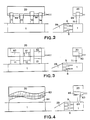
- FIG. 2 shows a variant in two vertical sections, in which the distribution box 1 is connected to a collecting container 20 via connecting lines 11-14.
- the height of the end of the connecting lines 11, 12, 13, 14, which goes into the collecting container 20, is adjustable, for example by sleeves 66 which can be displaced from the outside or by a telescopic design of the connecting lines which extends over at least part of the connecting lines. This creates a weir that is adjustable in height and thus makes the local pressure in the distributor individually adjustable.
- Figure 3 shows a modification in which the connecting lines 11, 12, 13 are designed as slots with underlying, adjustable surface elements 60, 61 and 62, which serve as overflow weirs. By adjusting these surface elements, the effective weir height can be changed locally, so that a local pressure correction in the distribution box 1 also takes place here.
- FIG. 4 Another possibility for influencing the pressure conditions is shown in FIG. 4, in which material is not drawn off via individual branch lines arranged across the machine width, but via an outlet slot 64 between distribution box 1 and collecting container 20, the outlet slot 64 covering the entire machine width goes.
- a vertical overflow weir 63 extending over the entire width is also provided in the collecting container 20, the height of which can be adjusted locally over the width from the outside.
- a change in the hydrostatic pressure in the distributor or in the nozzle can thereby be achieved simply by changing the weir height of the outlet slot 64.
- a displaceable screen 65 can also be provided, by means of which the outlet slot 64 can be individually adjusted over the width.
- branch lines or connecting slots can also be provided at other points of the headbox device, for example on the diffuser block 5, or in the nozzle chamber 29 immediately after the diffuser block or just before the outlet gap 8 or in between.
- FIG. 5 shows an analog headbox device in vertical section, in which a distributor 1, a diffuser 5 with a row of parallel channels 6, and a nozzle chamber 29 with an outlet gap 8 are again provided.
- the stock suspension flows from the nozzle chamber 29 onto the screen 32 of a paper machine which is guided over a breast roller 31.
- the front part 33 of the upper delimitation lip 7 of the nozzle chamber 29 can be individually adjusted over the width by means of a joint 34 and by adjusting device 35 distributed over the width of the outlet gap 8.
- the exit gap is delimited at the top by a diaphragm which is mounted on the upper lip, but is freely movable to a certain extent in relation to the upper lip. The gap width can then be changed using the adjustment devices attached to the panel.
- the amount of suspension emerging from the gap can be controlled locally independently over the width.
- the supply or discharge of fibrous suspension again takes place via branch lines 11 on the distributor 1 and also or optionally via branch lines 51 on the nozzle chamber 29, valves or pumps 36 or the designs shown in FIGS. 2-4 being provided for quantity regulation.
- branch lines are provided either selectively or in combination on the distributor 1, on the diffuser block 5 or on the nozzle chamber 29. Changes in the pressure curve can be compensated for as close as possible to the point of origin.
- the possibility is provided to provide branch lines 37 on the upper side of the distributor 1 or at another location. Instead, the branch lines can also be led directly out of the diffuser block 5.
- lines 39 are in the first diffuser stage, lines 40 into the second diffuser stage immediately after the paragraph to the first stage, or lines 41 into the third diffuser stage immediately after the paragraph to the second stage.
- supply lines can also be provided in the nozzle space 29 itself, for example lines 42 in the beginning of the nozzle space, directly behind the outlet openings 43 from the diffuser channels or lines 44, which are in the vicinity of the outlet gap 8 of the nozzle space 29 in the movable part 33 of the upper part Lippe flows out.
- these lines can be used to add or remove water or white water with a lower consistency or suspension, depending on the requirements for the purpose of pressure control or to change the consistency.
- Another possibility of regulating the pressure in the distributor 1 can be created by changing the distributor cross-section, e.g. through a movably designed rear wall 45 of the distributor.
- the mobility can be achieved in that the rear wall 45 can be adjusted either manually or by means of a control device over the width of the distribution box, as a result of which the pressure profile in the distributor can be set, or in that the rear wall 45 is designed as a flexible and deformable membrane which is automatic , for example with the help of a pressure pad on the back so that the same pressure prevails over the entire width of the distribution box.
- adjustment options 52 are necessary, which are to be provided immediately after the guide device, in front of the outlet gap or also in between, wherein the adjustment devices can also be attached at two and more positions in the machine direction.
- adjustable screens 46 in front of the inlet openings 38 of the diffuser channels 6 or corresponding adjustable screens 47 in front of the outlet openings 43 of the diffuser channels.
- adjustable screens 46 can consist of sliding elements, iris diaphragms, inflatable bodies or other elements.
- Suspension or water can also be supplied via lines 50 directly at the inlet 38 of the channels, or the channels can be narrowed by controllable pressure bodies 27.
- the increased pressure loss at the edges e.g. due to friction on the side walls 9 can be compensated for by changing the pressure loss of the guide device in the edge zones, e.g. is reduced, which is achieved by changing the passage cross section per unit width.
- FIG. 7 shows an example of a diffuser block 5 with a plurality of rows of stacked diffusers arranged one above the other.
- the cross section of the diffusers in the edge zone 48 on the side wall 9 is larger than in the adjoining central zone 49, so that the pressure loss in the stock suspension in the edge zone is somewhat smaller than in the middle and thus the increased Pressure losses in the peripheral zone can be compensated.
- the individual rows of step diffusers are offset from one another, which means that a lower nozzle pressure is created in the edge zone 48 due to the diffusers missing relative to the center 49.
- a larger material flow per unit of width is achieved in the edge zone by making additional bores or by reducing the pressure loss of the individual element of the guide device in the edge area, so that a pressure correction is also possible here.
- fundamental defects in the distribution board design or at another location on the paper machine can also be compensated for by changing and adapting the hole diameter or pressure loss across the web width.
- the branch lines 11 connected to the collecting line 20 can advantageously also be connected at the highest point of the distributor 1, which ensures that any air excretions can be safely removed.
- the connection for the diffuser 5 can be provided, so that the pressure control takes place in the immediate vicinity of the inlet of the diffuser.
- the collecting line can also be guided directly along the distributor 1, so that the branches 11 are formed by openings which connect the distributor 1 and the collecting line 20.
- FIG. 10 shows an example in which the diffuser is designed as a guide device which is known per se and which connects a distributor 1 with the lips 7 and an outlet gap 8 and which has two pipe systems 53 and which are connected in series and are separated by a space 55 bypassing the suspension 54 has.
- This intermediate space 55 is connected through branch openings 56 with an independently controllable or adjustable cross section to an overflow line 57, which at the same time shows a damping effect.
- FIG. 11 shows an analogous example in which controllability is achieved by means of slide 58. that change the cross section of the branch openings.
- the openings 59 can optionally also be brought forward to the beginning of the nozzle chamber 29.
Landscapes
- Paper (AREA)
Abstract
Claims (17)
Priority Applications (1)
| Application Number | Priority Date | Filing Date | Title |
|---|---|---|---|
| AT85904806T ATE47438T1 (de) | 1984-09-19 | 1985-09-16 | Stoffauflauf-vorrichtung fuer eine papiermaschine. |
Applications Claiming Priority (5)
| Application Number | Priority Date | Filing Date | Title |
|---|---|---|---|
| CH448984 | 1984-09-19 | ||
| CH4489/84 | 1984-09-19 | ||
| CH915/85 | 1985-02-28 | ||
| CH91585 | 1985-02-28 | ||
| PCT/EP1985/000473 WO1986001844A1 (fr) | 1984-09-19 | 1985-09-16 | Systeme de caisse de tete pour machine a papier, et procede pour son utilisation |
Publications (3)
| Publication Number | Publication Date |
|---|---|
| EP0195807A1 EP0195807A1 (fr) | 1986-10-01 |
| EP0195807B1 true EP0195807B1 (fr) | 1989-10-18 |
| EP0195807B2 EP0195807B2 (fr) | 1994-07-13 |
Family
ID=25686098
Family Applications (1)
| Application Number | Title | Priority Date | Filing Date |
|---|---|---|---|
| EP85904806A Expired - Lifetime EP0195807B2 (fr) | 1984-09-19 | 1985-09-16 | Systeme de caisse de tete pour machine a papier |
Country Status (5)
| Country | Link |
|---|---|
| US (3) | US4898643A (fr) |
| EP (1) | EP0195807B2 (fr) |
| DE (1) | DE3514554C3 (fr) |
| FI (1) | FI90359B (fr) |
| WO (1) | WO1986001844A1 (fr) |
Families Citing this family (86)
| Publication number | Priority date | Publication date | Assignee | Title |
|---|---|---|---|---|
| US4687548A (en) * | 1984-10-31 | 1987-08-18 | Valmet Oy | Method and apparatus for controlling distortion of fibre orientation in a paper web |
| FI73766C (fi) * | 1985-12-13 | 1987-11-09 | Ahlstroem Oy | INLOPPSLAODA FOER PAPPERSMASKIN. SIIRRETTY PAEIVAEMAEAERAE-FOERSKJUTET DATUM PL 14 ç 17.12.85. |
| CH671418A5 (fr) * | 1987-02-23 | 1989-08-31 | Escher Wyss Gmbh | |
| GB8711330D0 (en) * | 1987-05-14 | 1987-06-17 | Beloit Corp | Headbox |
| DE3802298A1 (de) * | 1987-06-09 | 1988-12-22 | Peter G Mercer | Verfahren und vorrichtung zum verbessern der homogenitaet der faserverteilung beim maschinellen herstellen einer faserstoffbahn |
| FI80090C (fi) * | 1987-12-23 | 1990-04-10 | Ahlstroem Valmet | Foerfarande och anordning i inloppslaodan av en pappersmaskin foer stabilisering av dess laeppstraole. |
| FI79365C (fi) * | 1988-03-28 | 1989-12-11 | Ahlstroem Valmet | Aktivdaempare foer daempning av tryckvibrationer i inloppslaodan och massaroersystemet i pappers- och kartongmaskiner. |
| AT392989B (de) * | 1988-05-17 | 1991-07-25 | Voith Ag J M | Stoffauflauf fuer papiermaschinen |
| DE3836062A1 (de) * | 1988-10-22 | 1990-04-26 | Voith Gmbh J M | Stoffauflauf fuer eine maschine zur herstellung von faserstoffbahnen, insbesondere von papierbahnen |
| FI81848C (fi) * | 1989-07-17 | 1990-12-10 | Valmet Paper Machinery Inc | Foerfarande foer reglering och on-line maetning av fiberorienteringen av en bana som framstaells pao en pappersmaskin. |
| FI896202A7 (fi) * | 1989-12-22 | 1991-06-23 | Ahlstroem Valmet | Menetelmä ja laite paperi-, kartonki- tai selluloosan kuivatuskoneen perälaatikossa |
| JPH03249297A (ja) * | 1990-02-26 | 1991-11-07 | Mitsubishi Heavy Ind Ltd | 抄紙機ヘッドボックスの流向調整方法 |
| DE4019235A1 (de) * | 1990-06-15 | 1991-12-19 | Voith Gmbh J M | Stoffauflauf |
| DE4019593C2 (de) * | 1990-06-20 | 1994-01-20 | Voith Gmbh J M | Stoffauflauf für Papiermaschinen |
| US5707495A (en) * | 1990-06-20 | 1998-01-13 | J.M. Voith Gmbh | Headbox for papermaking machine with more uniform flow |
| DE4025675C2 (de) * | 1990-08-14 | 1994-10-20 | Escher Wyss Gmbh | Stoffauflauf |
| DE4108759C2 (de) * | 1991-03-18 | 1997-07-31 | Schultz Hans Joachim Dr Ing | Verbindung zwischen einem Vielfachverteiler und einem Stoffauflauf |
| US5196091A (en) * | 1991-10-29 | 1993-03-23 | Beloit Technologies, Inc. | Headbox apparatus with stock dilution conduits for basis weight control |
| DE4213707A1 (de) * | 1992-04-25 | 1993-10-28 | Escher Wyss Gmbh | Stoffauflaufeinrichtung für eine Papiermaschine |
| JP3021219B2 (ja) * | 1992-10-29 | 2000-03-15 | 三菱重工業株式会社 | 抄紙機ヘッドボックスの端部流量調整装置 |
| DE4237310C2 (de) * | 1992-11-05 | 1994-07-07 | Voith Gmbh J M | Stoffauflauf mit Vorrichtung zur Einstellung der Faserorientierung |
| DE4241076C2 (de) * | 1992-11-05 | 1995-04-06 | Voith Gmbh J M | Stoffauflauf einer Papiermaschine mit variabler Unterlippe |
| FI934697L (fi) * | 1992-11-05 | 1994-05-06 | Voith Gmbh J M | Inloppslaoda foer en pappersmaskin med en modifierbar underlaepp |
| DE4237309A1 (fr) * | 1992-11-05 | 1993-04-08 | Voith Gmbh J M | |
| DE4239845C2 (de) * | 1992-11-05 | 1998-12-03 | Voith Gmbh J M | Verfahren zur Messung der Auswirkung von Verstellungen am Stoffauflauf und zur Korrektur des Flächengewichts- und Faserorientierungs-Querprofils |
| DE4237307C2 (de) * | 1992-11-05 | 1994-08-18 | Voith Gmbh J M | Stoffauflauf einer eine Faserbahn bildenden Maschine |
| DE4239647C2 (de) * | 1992-11-26 | 1994-11-03 | Voith Gmbh J M | Verfahren und Vorrichtung zur Vergleichmäßigung des Flächengewichtsquerprofils mittels Siebkreislaufsektionierung |
| DE4239644C2 (de) * | 1992-11-26 | 1994-10-27 | Voith Gmbh J M | Stoffauflauf einer Papiermaschine mit Welleneinsatz |
| FI103995B (fi) * | 1993-06-17 | 1999-10-29 | Valmet Paper Machinery Inc | Menetelmä ja laite sekä säätöjärjestely paperikoneessa paperirainan poikittaisen profiilin hallinnassa |
| DE4320243C2 (de) * | 1993-06-18 | 1996-02-22 | Voith Sulzer Papiermasch Gmbh | Stoffauflauf für eine Papiermaschine |
| DE4321268C2 (de) * | 1993-06-28 | 1996-08-14 | Voith Gmbh J M | Stoffauflauf und Verfahren zur Erzeugung einer mehrschichtigen und mehrlagigen Papierbahn |
| EP1099793B1 (fr) * | 1993-07-01 | 2006-08-02 | Metso Paper, Inc. | Procédé et dispositif pour la régulation d' une caisse de tête |
| DE4323263C2 (de) * | 1993-07-12 | 2001-11-29 | Voith Paper Patent Gmbh | Verfahren zur sektionalen Beeinflussung der Stoffdichte und der Faserorientierung in einem Stoffauflauf einer Papiermaschine und Stoffauflauf zur Durchführung des Verfahrens |
| DE4408713A1 (de) * | 1994-03-15 | 1995-09-21 | Escher Wyss Gmbh | Verfahren und Vorrichtung zum Führen einer Materialbahn |
| DE4409415C5 (de) * | 1994-03-18 | 2005-02-17 | Voith Sulzer Papiermaschinen Gmbh | Dosiervorrichtung für einen Stoffauflauf einer Papiermaschine |
| CA2121967C (fr) * | 1994-04-22 | 1996-05-21 | Douglas Henry Offerhaus | Methode pour aplanir les defauts surperficiels dans la caisse ded tete d'une machine a fabriquer le papier |
| DE4417461C2 (de) * | 1994-05-19 | 1998-12-03 | Voith Sulzer Papiermasch Gmbh | Zentralverteiler |
| DE4422907C2 (de) * | 1994-06-30 | 1997-03-06 | Voith Gmbh J M | Sektionale Stoffzuführung des Stoffauflaufs einer Papiermaschine |
| US5510005A (en) * | 1994-07-25 | 1996-04-23 | Westvaco Corporation | Venturi headbox for a papermaking machine |
| US5549793A (en) * | 1994-08-02 | 1996-08-27 | Abb Industrial Systems, Inc. | Control of dilution lines in a dilution headbox of a paper making machine |
| DE4433445C1 (de) * | 1994-09-20 | 1996-03-28 | Voith Gmbh J M | Stoffauflauf einer Papiermaschine |
| DE4437181C2 (de) * | 1994-10-18 | 1997-02-27 | Voith Sulzer Papiermasch Gmbh | Stoffauflauf für eine Papiermaschine |
| DE9416731U1 (de) * | 1994-10-18 | 1995-01-12 | Sulzer-Escher Wyss Gmbh, 88212 Ravensburg | Stoffauflauf für eine Papiermaschine |
| US5560807A (en) * | 1995-03-29 | 1996-10-01 | Beloit Technologies, Inc. | Headbox additive injection system |
| US5603806A (en) * | 1995-06-01 | 1997-02-18 | Valmet Corporation | Method and apparatus for lateral alignment of the cross-direction quality profile of a web in a paper machine |
| US5626722A (en) * | 1995-06-01 | 1997-05-06 | Valmet Corporation | Headbox of a paper/board machine |
| EP0774540B1 (fr) | 1995-11-17 | 2002-02-27 | Voith Paper Patent GmbH | Procédé pour régler la longueur de rupture dans le sens transversal d'une bande fibreuse en mouvement |
| US5853545A (en) * | 1996-03-08 | 1998-12-29 | Valmet-Karlstad Ab | Arrangement for feeding stock to a headbox in a papermaking machine |
| SE506322C2 (sv) * | 1996-03-08 | 1997-12-01 | Valmet Karlstad Ab | Anordning för matning av mäld till en inloppslåda i en pappersmaskin |
| US5882482A (en) * | 1996-06-10 | 1999-03-16 | Beloit Technologies, Inc. | Convergent flow headbox |
| US6235159B1 (en) | 1996-06-10 | 2001-05-22 | Beloit Technologies, Inc. | Convergent flow headbox |
| FI98938C (fi) * | 1996-06-20 | 1997-09-10 | Valmet Corp | Laitteisto laimennusvirtauksen yhdistämiseksi paperikoneen/kartonkikoneen jakotukista johdettuun massavirtaukseen |
| DE59705631D1 (de) * | 1996-08-14 | 2002-01-17 | Voith Paper Patent Gmbh | Stoffauflauf und Verfahren zur Verteilung einer Faserstoffsuspension im Stoffauflauf einer Papiermaschine |
| DE19654390A1 (de) * | 1996-12-27 | 1998-07-02 | Basf Ag | Verfahren zur Herstellung von Papier |
| FI115645B (fi) * | 1997-01-14 | 2005-06-15 | Metso Paper Inc | Paperikoneen perälaatikko, jossa on reunasyöttöjärjestelyt |
| US5833808A (en) * | 1997-01-21 | 1998-11-10 | Beloit Technologies, Inc. | Method of controlling curl employing inline headbox edge flow control valve |
| US20020084051A1 (en) * | 1998-02-06 | 2002-07-04 | Andritz-Patenverwaltungs-Gesellschaft M.B.H. | Process and a device for the formation of fiberboard |
| US20050045299A1 (en) * | 1998-02-06 | 2005-03-03 | Franz Petschauer | Process and a device for the formation of fiberboard |
| FI113284B (fi) | 1998-02-13 | 2004-03-31 | Metso Paper Inc | Paperikoneen/kartonkikoneen perälaatikko, jolla rainan neliöpaino on säädettävissä |
| US6004431A (en) * | 1998-02-24 | 1999-12-21 | Beloit Technologies, Inc. | Headbox with active local flow control |
| US6146500A (en) * | 1998-06-19 | 2000-11-14 | Kimberly-Clark Worldwide, Inc. | Suction breast roll former and method, with flexible headbox roof |
| US6033527A (en) * | 1998-07-06 | 2000-03-07 | Beloit Technologies, Inc. | Paper machine edge fiber alignment control by angled headbox sides |
| DE19835295A1 (de) * | 1998-08-05 | 2000-02-10 | Voith Sulzer Papiertech Patent | Verfahren zur Einstellung eines gleichmäßigen Eigenschaftsquerprofils einer Papierbahn |
| US6117272A (en) * | 1998-09-03 | 2000-09-12 | Voith Sulzer Papiermaschinen | Device and process for metering auxiliary materials into the flow box of a paper machine |
| DE19908898A1 (de) | 1999-03-02 | 2000-09-07 | Voith Sulzer Papiertech Patent | Verfahren zur Zudosierung eines fluiden Mediums in einen Suspensionsstrom eines Stoffauflaufes und Stoffauflauf |
| US6294051B1 (en) | 1999-04-13 | 2001-09-25 | Kimberly-Clark Worldwide, Inc. | Method for improving the edge strength of a fibrous mat |
| FI113672B (fi) | 1999-04-28 | 2004-05-31 | Metso Paper Inc | Menetelmä ja laitteisto laimennusnesteen sekoittamiseksi massavirtaukseen paperikoneessa tai kartonkikoneessa |
| DE19923149A1 (de) * | 1999-05-20 | 2000-11-23 | Voith Sulzer Papiertech Patent | Regelung des Druckes in einer Stoffauflaufdüse |
| DE19926809A1 (de) * | 1999-06-13 | 2000-12-14 | Voith Sulzer Papiertech Patent | Turbulenzerzeuger |
| US6270625B1 (en) * | 1999-06-29 | 2001-08-07 | The Mead Corporation | Method for manufacturing colored stripped paper |
| WO2001029297A1 (fr) * | 1999-10-20 | 2001-04-26 | Auckland Uniservices Limited | Procede de separation de fibres |
| US6770171B2 (en) * | 1999-12-30 | 2004-08-03 | Metso Paper, Inc. | Method and system for controlling headbox in a paper/board machine |
| GB2367564B (en) | 2000-10-04 | 2004-02-18 | Sandusky Walmsley Ltd | Method of and apparatus for distribution of paper stock in paper or board making machinery |
| FI109136B (fi) * | 2000-12-07 | 2002-05-31 | Metso Paper Inc | Menetelmä ja laite rainan kuiva-aineprofiilin säätämiseksi paperikoneen/kartonkikoneen viiraosalla |
| DE10208610B4 (de) * | 2002-02-27 | 2014-03-06 | Voith Patent Gmbh | Verfahren zum Verteilen einer Faserstoffsuspension im Stoffauflauf einer Papier- oder Kartonmaschine und Stoffauflauf |
| FI113197B (fi) * | 2002-09-20 | 2004-03-15 | Metso Paper Inc | Levityslaite |
| DE10341448A1 (de) * | 2003-09-09 | 2005-03-31 | Voith Paper Patent Gmbh | Siebpartie in einer Maschine zur Herstellung einer Faserstoffbahn |
| SE0502140L (sv) * | 2005-09-28 | 2006-11-14 | Kvaerner Pulping Tech | Apparat för inblandning av ånga till ett flöde av cellulosamassa |
| WO2007089900A2 (fr) | 2006-02-01 | 2007-08-09 | Astenjohnson, Inc. | Caisse de tete et systeme d'alimentation en pate de machine a papier |
| WO2012155052A1 (fr) * | 2011-05-11 | 2012-11-15 | Hollingsworth & Vose Company | Systèmes et procédés de fabrication de bandes fibreuses |
| WO2013016515A1 (fr) | 2011-07-27 | 2013-01-31 | Hollingsworth & Vose Company | Systèmes et procédés pour réaliser des bandes fibreuses |
| US8758559B2 (en) | 2011-07-27 | 2014-06-24 | Hollingsworth & Vose Company | Systems and methods for making fiber webs |
| US8871059B2 (en) * | 2012-02-16 | 2014-10-28 | International Paper Company | Methods and apparatus for forming fluff pulp sheets |
| CN104120616B (zh) * | 2014-07-25 | 2016-05-18 | 陕西科技大学 | 免回流可微调方锥总管 |
| FI12114U1 (fi) * | 2018-05-25 | 2018-08-15 | Valmet Technologies Oy | Reunasyöttöväline lisäsyöttövirtauksen järjestämiseksi kuiturainakoneen perälaatikon turbulenssigeneraattoriin |
| WO2021207626A1 (fr) * | 2020-04-09 | 2021-10-14 | Andritz Inc. | Régulation de l'écoulement de tranches de pâte liquide à travers une caisse d'arrivée |
Family Cites Families (32)
| Publication number | Priority date | Publication date | Assignee | Title |
|---|---|---|---|---|
| US2688276A (en) * | 1951-05-11 | 1954-09-07 | Marathon Corp | Head box for paper machines |
| US2956623A (en) * | 1957-04-01 | 1960-10-18 | Ikavalko Erkki | Process and apparatus for delivering paper stock to a wire mesh pulley belt |
| US2904461A (en) * | 1957-08-23 | 1959-09-15 | Beloit Iron Works | Method and apparatus for controlling flow of stock through a slice jet |
| US2965623A (en) * | 1957-11-08 | 1960-12-20 | Borden Co | Polymerization of vinyl esters |
| DE1165397B (de) * | 1958-01-23 | 1964-03-12 | Rice Barton Corp | Stoffauflauf fuer Papiermaschinen |
| BE658601A (fr) * | 1964-01-23 | |||
| US3434923A (en) * | 1965-08-04 | 1969-03-25 | Beloit Corp | Headbox of a papermaking machine |
| US3547775A (en) * | 1966-04-29 | 1970-12-15 | Industrial Nucleonics Corp | Means and method for modulating fiber stock flow in papermaking headbox in response to paper sheet product parameters |
| FR1519450A (fr) * | 1967-04-19 | 1968-03-29 | Industrial Nucleonics Corp | Procédé et équipement pour la fabrication de produits en feuille, notamment en papier et en matière plastique |
| US3556935A (en) * | 1968-04-03 | 1971-01-19 | Procter & Gamble | Papermaking headbox with adjustable hydraulic nozzle and slice |
| GB1216114A (en) * | 1968-07-04 | 1970-12-16 | St Annes Board Mill Co Ltd | Flowbox system |
| US3575800A (en) * | 1968-11-13 | 1971-04-20 | Beloit Corp | Multiple gallonage header for paper machine headbox |
| US3573160A (en) * | 1969-01-29 | 1971-03-30 | Kasimir Lopas | Tapered manifold stock distribution system for a papermaking machine with movable wall therein |
| DE1941424C3 (de) * | 1969-08-14 | 1980-07-10 | Escher Wyss Gmbh, 7980 Ravensburg | Stoffauflauf für eine Papiermaschine |
| DE7034695U (de) * | 1970-09-18 | 1971-12-23 | Voith Gmbh J M | Stoffauflauf mit einer vielzahl der auslaufduese vorgeschalteten kanaelen. |
| DE2151906A1 (de) * | 1971-10-19 | 1973-04-26 | Bellmer Geb Kg Maschf | Stoffauflauf fuer papiermaschinen |
| US3791918A (en) * | 1972-03-08 | 1974-02-12 | Valmet Oy | Headbox of a paper making machine having multiple, vertically inclined vanes |
| ZA735253B (en) * | 1972-10-12 | 1974-07-31 | Crown Zellerbach Corp | Apparatus and method for delivering a fiber slurry |
| US3960654A (en) * | 1974-08-19 | 1976-06-01 | Westvaco Corporation | Shear pump headbox |
| FI50650C (fi) * | 1975-02-25 | 1976-05-10 | Valmet Oy | Paperikoneen hydraulinen perälaatikko. |
| CH608049A5 (fr) * | 1976-01-23 | 1978-12-15 | Escher Wyss Gmbh | |
| CH608532A5 (fr) * | 1976-01-27 | 1979-01-15 | Escher Wyss Gmbh | |
| CH608255A5 (fr) * | 1976-05-11 | 1978-12-29 | Escher Wyss Gmbh | |
| US4285767A (en) * | 1978-03-13 | 1981-08-25 | Beloit Corporation | Headbox having adjustable flow passages |
| FR2429867A1 (fr) * | 1978-06-30 | 1980-01-25 | Centre Tech Ind Papier | Commande du fonctionnement de la caisse de tete d'une machine a papier |
| DE2912152A1 (de) * | 1979-03-28 | 1980-10-09 | Fr Schiettinger Niederlassung | Vorrichtung zur regelung des flaechengewicht-querprofils bei der erzeugung von papier, karton, pappe o.dgl. |
| ATA755479A (de) * | 1979-11-29 | 1981-08-15 | Stroemungsmasch Anst | Stoffauflauf fuer siebbandpressen |
| AT363776B (de) * | 1980-01-31 | 1981-08-25 | Stroemungsmasch Anst | Stoffauflauf fuer siebbandpressen |
| AT377026B (de) * | 1980-12-19 | 1985-01-25 | Escher Wyss Gmbh | Stoffauflauf fuer eine papiermaschine |
| US4414062A (en) * | 1981-11-18 | 1983-11-08 | Valmet Oy | Headbox of a paper machine |
| AT387410B (de) * | 1983-06-09 | 1989-01-25 | Escher Wyss Gmbh | Stoffauflauf fuer eine papiermaschine |
| US4687548A (en) * | 1984-10-31 | 1987-08-18 | Valmet Oy | Method and apparatus for controlling distortion of fibre orientation in a paper web |
-
1985
- 1985-04-23 DE DE3514554A patent/DE3514554C3/de not_active Expired - Fee Related
- 1985-09-16 WO PCT/EP1985/000473 patent/WO1986001844A1/fr not_active Ceased
- 1985-09-16 EP EP85904806A patent/EP0195807B2/fr not_active Expired - Lifetime
-
1986
- 1986-05-09 FI FI861944A patent/FI90359B/fi not_active Application Discontinuation
- 1986-05-19 US US06/873,196 patent/US4898643A/en not_active Expired - Lifetime
-
1988
- 1988-06-13 US US07/206,496 patent/US4888094A/en not_active Expired - Lifetime
- 1988-11-17 US US07/272,340 patent/US4897158A/en not_active Expired - Lifetime
Also Published As
| Publication number | Publication date |
|---|---|
| DE3514554C3 (de) | 1998-01-08 |
| US4898643A (en) | 1990-02-06 |
| FI90359B (fi) | 1993-10-15 |
| FI861944A7 (fi) | 1986-05-09 |
| FI861944A0 (fi) | 1986-05-09 |
| EP0195807B2 (fr) | 1994-07-13 |
| DE3514554A1 (de) | 1986-03-27 |
| DE3514554C2 (de) | 1994-06-16 |
| US4888094A (en) | 1989-12-19 |
| US4897158A (en) | 1990-01-30 |
| WO1986001844A1 (fr) | 1986-03-27 |
| EP0195807A1 (fr) | 1986-10-01 |
Similar Documents
| Publication | Publication Date | Title |
|---|---|---|
| EP0195807B2 (fr) | Systeme de caisse de tete pour machine a papier | |
| DE4019593C2 (de) | Stoffauflauf für Papiermaschinen | |
| AT392807B (de) | Stoffauflauf fuer eine papiermaschine od.dgl. | |
| DE4005281C2 (de) | Stoffauflauf mit Regelung des Flächengewicht-Querprofiles über die Verdünnung der Fasersuspension | |
| DE69434813T2 (de) | Verfahren und Vorrichtung zur Regelung eines Stoffauflaufkastens | |
| DE69913450T2 (de) | Stoffauflauf zur Verteilung von Faserstoffsuspension und Zusatzstoffe | |
| DE4323263A1 (de) | Stoffauflauf einer Papiermaschine | |
| DE69707256T3 (de) | DOPPELSIEBFORMER MIT ROLLE UND KLINGE FüR EINE PAPIERMASCHINE | |
| WO2010069652A1 (fr) | Caisson de tête pour machine de fabrication d'une bande de matière fibreuse | |
| WO1993022495A1 (fr) | Agencement de caisse de tete pour machines a papier | |
| DE3306145A1 (de) | Verfahren zur herstellung von papier | |
| DE9115296U1 (de) | Stoffauflauf | |
| AT392989B (de) | Stoffauflauf fuer papiermaschinen | |
| DE4409415C5 (de) | Dosiervorrichtung für einen Stoffauflauf einer Papiermaschine | |
| DE1511218B2 (de) | Papierbrei-aufgabevorrichtung fuer papiermaschinen | |
| WO1982003413A1 (fr) | Machine a papier ayant une caisse de tete a plusieurs tuyeres | |
| DE1290797B (de) | Stoffauflaufkasten fuer eine Papiermaschine | |
| DE3045279T1 (de) | Method and device in a paper making machine | |
| DE3639823C2 (fr) | ||
| DE4140657C2 (de) | Stoffauflauf | |
| DE2830046C2 (de) | Einrichtung zur Regelung des Querprofils der Faserbahn in einer Papiermaschine | |
| DE4025675C2 (de) | Stoffauflauf | |
| DE2607310C3 (de) | Geschlossener Stoffauflauf für eine Papiermaschine | |
| DE19634993A1 (de) | Verfahren und Vorrichtung zum Einstellen des Stoffdichte- und Faserorientierungsprofils in einem Stoffauflauf | |
| DE1906334C3 (de) | Vorrichtung zum Herstellen einer faserstoffhaltigen Bahn mit einer Einlage verhältnismäßig hoher Festigkeit |
Legal Events
| Date | Code | Title | Description |
|---|---|---|---|
| PUAI | Public reference made under article 153(3) epc to a published international application that has entered the european phase |
Free format text: ORIGINAL CODE: 0009012 |
|
| 17P | Request for examination filed |
Effective date: 19860423 |
|
| AK | Designated contracting states |
Kind code of ref document: A1 Designated state(s): AT DE GB IT SE |
|
| RIN1 | Information on inventor provided before grant (corrected) |
Inventor name: SEIDER, WERNER Inventor name: STOTZ, WOLF-GUNTER Inventor name: ZEMBROT, ANTON Inventor name: KURTZ, RUEDIGER Inventor name: HOLIK, HERBERT Inventor name: DAHL, HANS Inventor name: BUBIK, ALFRED Inventor name: WEISSHUHN, ELMER |
|
| 17Q | First examination report despatched |
Effective date: 19871117 |
|
| GRAA | (expected) grant |
Free format text: ORIGINAL CODE: 0009210 |
|
| AK | Designated contracting states |
Kind code of ref document: B1 Designated state(s): AT DE GB IT SE |
|
| ITF | It: translation for a ep patent filed | ||
| REF | Corresponds to: |
Ref document number: 47438 Country of ref document: AT Date of ref document: 19891115 Kind code of ref document: T |
|
| REF | Corresponds to: |
Ref document number: 3573813 Country of ref document: DE Date of ref document: 19891123 |
|
| GBT | Gb: translation of ep patent filed (gb section 77(6)(a)/1977) | ||
| PLBI | Opposition filed |
Free format text: ORIGINAL CODE: 0009260 |
|
| 26 | Opposition filed |
Opponent name: VALMET PAPER MACHINERY INC. Effective date: 19900718 |
|
| ITTA | It: last paid annual fee | ||
| PUAA | Information related to the publication of a b2 document modified |
Free format text: ORIGINAL CODE: 0009299PMAP |
|
| PUAH | Patent maintained in amended form |
Free format text: ORIGINAL CODE: 0009272 |
|
| STAA | Information on the status of an ep patent application or granted ep patent |
Free format text: STATUS: PATENT MAINTAINED AS AMENDED |
|
| 27A | Patent maintained in amended form |
Effective date: 19940713 |
|
| AK | Designated contracting states |
Kind code of ref document: B2 Designated state(s): SE |
|
| PG25 | Lapsed in a contracting state [announced via postgrant information from national office to epo] |
Ref country code: SE Free format text: LAPSE BECAUSE OF NON-PAYMENT OF DUE FEES Effective date: 19940917 |
|
| R27A | Patent maintained in amended form (corrected) |
Effective date: 19940713 |
|
| EUG | Se: european patent has lapsed |
Ref document number: 85904806.8 Effective date: 19941017 |
|
| GBTA | Gb: translation of amended ep patent filed (gb section 77(6)(b)/1977) |
Effective date: 19950613 |
|
| PGFP | Annual fee paid to national office [announced via postgrant information from national office to epo] |
Ref country code: SE Payment date: 19950804 Year of fee payment: 11 |
|
| APAC | Appeal dossier modified |
Free format text: ORIGINAL CODE: EPIDOS NOAPO |
|
| APAC | Appeal dossier modified |
Free format text: ORIGINAL CODE: EPIDOS NOAPO |
|
| PGFP | Annual fee paid to national office [announced via postgrant information from national office to epo] |
Ref country code: GB Payment date: 19990817 Year of fee payment: 15 |
|
| PG25 | Lapsed in a contracting state [announced via postgrant information from national office to epo] |
Ref country code: GB Free format text: LAPSE BECAUSE OF NON-PAYMENT OF DUE FEES Effective date: 20000916 |
|
| PGFP | Annual fee paid to national office [announced via postgrant information from national office to epo] |
Ref country code: AT Payment date: 20000919 Year of fee payment: 16 |
|
| PGFP | Annual fee paid to national office [announced via postgrant information from national office to epo] |
Ref country code: DE Payment date: 20001006 Year of fee payment: 16 |
|
| GBPC | Gb: european patent ceased through non-payment of renewal fee |
Effective date: 20000916 |
|
| PG25 | Lapsed in a contracting state [announced via postgrant information from national office to epo] |
Ref country code: AT Free format text: LAPSE BECAUSE OF NON-PAYMENT OF DUE FEES Effective date: 20010916 |
|
| PG25 | Lapsed in a contracting state [announced via postgrant information from national office to epo] |
Ref country code: DE Free format text: LAPSE BECAUSE OF NON-PAYMENT OF DUE FEES Effective date: 20020501 |
|
| APAH | Appeal reference modified |
Free format text: ORIGINAL CODE: EPIDOSCREFNO |
|
| PLAB | Opposition data, opponent's data or that of the opponent's representative modified |
Free format text: ORIGINAL CODE: 0009299OPPO |