EP0195845A2 - Procédé d'équilibrage d'une façon permanente d'un rotor, en particulier d'une molette et arrangement de circuit à cet effet - Google Patents
Procédé d'équilibrage d'une façon permanente d'un rotor, en particulier d'une molette et arrangement de circuit à cet effet Download PDFInfo
- Publication number
- EP0195845A2 EP0195845A2 EP85112577A EP85112577A EP0195845A2 EP 0195845 A2 EP0195845 A2 EP 0195845A2 EP 85112577 A EP85112577 A EP 85112577A EP 85112577 A EP85112577 A EP 85112577A EP 0195845 A2 EP0195845 A2 EP 0195845A2
- Authority
- EP
- European Patent Office
- Prior art keywords
- unbalance
- determined
- measurement signal
- compensation
- unbalance measurement
- Prior art date
- Legal status (The legal status is an assumption and is not a legal conclusion. Google has not performed a legal analysis and makes no representation as to the accuracy of the status listed.)
- Granted
Links
Images
Classifications
-
- G—PHYSICS
- G01—MEASURING; TESTING
- G01M—TESTING STATIC OR DYNAMIC BALANCE OF MACHINES OR STRUCTURES; TESTING OF STRUCTURES OR APPARATUS, NOT OTHERWISE PROVIDED FOR
- G01M1/00—Testing static or dynamic balance of machines or structures
- G01M1/30—Compensating imbalance
- G01M1/32—Compensating imbalance by adding material to the body to be tested, e.g. by correcting-weights
- G01M1/323—Compensating imbalance by adding material to the body to be tested, e.g. by correcting-weights using balancing liquid
Definitions
- the invention relates to a method according to the preamble of claim 1 and a circuit arrangement according to the preamble of claim 9.
- the unbalance measurement signal emitted by the sensor is influenced by the machine behavior, which is unpredictable and changes constantly. As already mentioned, this is due to the fact that the mass of the rotor changes constantly during material processing. Also externally caused interference vibrations from rotating rotors, especially in material processing machine, e.g. B. grinding machine, and interference resulting from storage can lead to fluctuations in the unbalance measurement signal. A further part of the fluctuations in the unbalance measurement signal also have short-term interference vibrations, which arise when the compensating liquid is injected into the compensating armor.
- the object of the invention is therefore to provide a method and a circuit arrangement of the type mentioned at the outset in which undesired influences from disturbances or fluctuations in the unbalance measurement signal on the compensation operation or the compensation operations are eliminated.
- the invention avoids over-regulation behavior in the compensation processes and the imbalance measurements carried out at the same time, and a calming of the control loop is achieved. This is made possible by the fact that the tolerance within which permissible imbalance fluctuations are permitted is derived from the fluctuations in the imbalance measurement signal, which is continuously determined.
- the method according to the invention is preferably used in the method described in the older German patent application P 35 03 724.5 after measuring the initial unbalance and before initiating the compensation process, ie. H. before introducing the test amount of balancing liquid.
- the respective disrupted tolerance is dependent on the desired one
- Accuracy allows somewhat larger peak values of the unbalance measurement signal than they correspond to the maximum and minimum values determined within the specific time period.
- the maximum and minimum value of the unbalance measurement signal can be determined within a period of less than 5 seconds, in particular from approximately 1 to 2 seconds.
- a value greater than 1, preferably between 1 and 2 is selected for the multiplier by which the difference between the determined maximum and minimum values is multiplied.
- the interference factor is determined by comparing the values of the unbalance measurement signal before and after the phase-dependent rectification.
- phase-dependent rectification DE-AS 11 08 475, Hofmann Info No. 2 from Gebr. Hofmann GmbH & Co. KG, D-6102 Pfungstadt, Hofmann News No. 5 from Gebr. Hofmann GmbH & Co. KG, D-6102 Pfungstadt
- the unbalance vibration coming from the transducers is rectified with a rotation-frequency rectangular phase reference voltage and then integrated via an RC element.
- two rectifiers are used, which are 90 phase-shifted in their effect.
- Two DC voltages are formed which contain the unbalance signal according to size and phase position.
- phase-dependent rectification With phase-dependent rectification, all interference vibrations and even harmonics are filtered out.
- the odd harmonics are determined by means of a between the transducers and the Circuit for phase-dependent rectification inserted filter, which is relatively broadband, suppressed.
- This filter can be designed as a so-called tracking filter (auto-tracking measurement method in Hofmann News No. 5 from Gebr. Hofmann GmbH & Co. KG, D-6102 Pfungstadt) and is adjusted with the speed of the balancing body over the entire speed range. In this way, the interference signals contained in the measurement signal are suppressed.
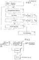
- the unbalance signal coming from the transmitter and still containing the interference signals is fed to a broadband filter 1.
- the output of the broadband filter 1 is connected to the input of a circuit 2 for phase-dependent rectification, as is known for example from DE-AS 11 08 475, and to a comparator 3.
- the output of the circuit 2 is connected to a further input of the comparator 3.
- the output signal of the circuit 2 is also passed on to a storage and / or display device for the unbalance size and unbalance angle position.
- the determined in comparator 3 The difference between the input and output signals of the circuit 2 for the phase-sensitive rectification represents a measure of the interference component and is used as the interference factor N with the multiplier TM determined as a function of permissible fluctuations in the unbalance measurement signal in a multiplier 4 connected to the output of the comparator 3 Determination of the tolerance T multiplied according to the following equation:
- one input of the comparator 3 is connected to the input of the circuit 2.
- This input of the comparator for determining the interference factor N can also be connected to the input of the broadband filter 3, which is designed in particular as a tracking filter.
- the interference component N (USmax-USmin) is determined and compared with the previously determined interference component N. If there is a difference between the two interference components N and N, the interference component N is multiplied n n-1 by the multiplier TM to redefine the tolerance T.
- the interference component N is determined by comparing the n unbalance measurement signals which occur at a point between the transmitter and the phase-controlled rectifier circuit 2, in particular at the input of the phase-controlled rectifier circuit 2 and the output of this circuit 2 are present. If there is a difference between the interference components N and the previously determined n interference components N, the interference component N is multiplied n-1 by the multiplier TM n to redefine the tolerance.
- the tolerance T can be determined anew by one or the other method.
- the tolerance can thus be made very small by the two exemplary embodiments, and this can lead to over-regulation behavior under certain circumstances.
- a method can preferably be used at the same time by which the tolerance change is limited downwards. It is assumed that a small tolerance T automatically leads to a larger fluctuation range in the phase position, so that the smallest tolerance is due to a maximum permissible fluctuation range of the phase position can be determined.
- the phase of the unbalance signal is measured and the fluctuation range of the phase position is determined. As soon as this fluctuation range reaches a certain value, in particular 0.5 to 10, e.g. due to larger disturbances, the corresponding disturbance component N is determined from the then existing unbalance measurement signal and multiplied to redefine the tolerance by the multiplier TM determined as a function of permissible fluctuations in the unbalance measurement signal in accordance with the above equation.
Landscapes
- Physics & Mathematics (AREA)
- General Physics & Mathematics (AREA)
- Testing Of Balance (AREA)
- Constituent Portions Of Griding Lathes, Driving, Sensing And Control (AREA)
- Grinding Of Cylindrical And Plane Surfaces (AREA)
Priority Applications (1)
| Application Number | Priority Date | Filing Date | Title |
|---|---|---|---|
| AT85112577T ATE49054T1 (de) | 1985-03-26 | 1985-10-04 | Verfahren zum fortlaufenden ausgleich einer unwucht eines rotors, insbesondere einer schleifscheibe und schaltungsanordnung hierfuer. |
Applications Claiming Priority (2)
| Application Number | Priority Date | Filing Date | Title |
|---|---|---|---|
| DE3510950 | 1985-03-26 | ||
| DE19853510950 DE3510950A1 (de) | 1985-03-26 | 1985-03-26 | Verfahren zum fortlaufenden ausgleich einer unwucht eines rotors, insbesondere einer schleifscheibe und schaltungsanordnung hierfuer |
Publications (3)
| Publication Number | Publication Date |
|---|---|
| EP0195845A2 true EP0195845A2 (fr) | 1986-10-01 |
| EP0195845A3 EP0195845A3 (en) | 1988-05-18 |
| EP0195845B1 EP0195845B1 (fr) | 1989-12-27 |
Family
ID=6266379
Family Applications (1)
| Application Number | Title | Priority Date | Filing Date |
|---|---|---|---|
| EP85112577A Expired EP0195845B1 (fr) | 1985-03-26 | 1985-10-04 | Procédé d'équilibrage d'une façon permanente d'un rotor, en particulier d'une molette et arrangement de circuit à cet effet |
Country Status (5)
| Country | Link |
|---|---|
| US (1) | US4688355A (fr) |
| EP (1) | EP0195845B1 (fr) |
| JP (1) | JPH0658279B2 (fr) |
| AT (1) | ATE49054T1 (fr) |
| DE (1) | DE3510950A1 (fr) |
Families Citing this family (8)
| Publication number | Priority date | Publication date | Assignee | Title |
|---|---|---|---|---|
| EP0305522A4 (en) * | 1987-03-19 | 1990-09-26 | Lipetsky Stankostroitelny Zavod | Device for automatic balancing of abrasive disks |
| SE461279B (sv) * | 1988-05-30 | 1990-01-29 | Electrolux Ab | Metod foer balansering av en kring en vaesentligen horisontell axel roterande behaallare |
| US5005439A (en) * | 1989-07-14 | 1991-04-09 | Barry Wright Corporation | Inertia force generating device |
| US5343408A (en) * | 1991-08-09 | 1994-08-30 | Industrial Technology Research Institute | Device for on-line automatic fluid injection balancing system |
| US5354186A (en) * | 1993-08-12 | 1994-10-11 | The Board Of Regents Of The University Of Michigan | Machine balancer with peristaltic fluid pump |
| DE19729172C1 (de) * | 1997-07-08 | 1998-07-30 | Hofmann Mes Und Auswuchttechni | Verfahren zum fortlaufenden Ausgleich einer Unwucht eines Rotors |
| US7267029B2 (en) * | 2001-11-14 | 2007-09-11 | Lord Corporation | Balancing device for a rotating member and associated methods |
| JP6174545B2 (ja) * | 2014-10-17 | 2017-08-02 | ファナック株式会社 | 臭気センサを用いた切削液の状態監視装置 |
Family Cites Families (5)
| Publication number | Priority date | Publication date | Assignee | Title |
|---|---|---|---|---|
| US3646601A (en) * | 1969-10-22 | 1972-02-29 | Gen Motors Corp | Off-angle balance correction method and apparatus |
| DE2357629A1 (de) * | 1973-11-19 | 1975-05-28 | Hofmann Maschf Geb | Vorrichtung zum ausgleich der unwucht eines rotierenden koerpers, insbesondere einer schleifscheibe |
| JPS5783746A (en) * | 1980-11-11 | 1982-05-25 | Matsushita Electric Ind Co Ltd | Correction method of dynamic unbalance of rotating body |
| GB2097101B (en) * | 1981-04-20 | 1984-11-14 | Kerlin Jack Harnsworth | Unbalance compensator and method of distributing balancing mass in same |
| US4432253A (en) * | 1981-04-20 | 1984-02-21 | Balance Dynamics Co. | Unbalance compensator |
-
1985
- 1985-03-26 DE DE19853510950 patent/DE3510950A1/de active Granted
- 1985-10-04 EP EP85112577A patent/EP0195845B1/fr not_active Expired
- 1985-10-04 AT AT85112577T patent/ATE49054T1/de not_active IP Right Cessation
-
1986
- 1986-03-20 JP JP61063860A patent/JPH0658279B2/ja not_active Expired - Lifetime
- 1986-03-25 US US06/843,608 patent/US4688355A/en not_active Expired - Lifetime
Also Published As
| Publication number | Publication date |
|---|---|
| DE3510950C2 (fr) | 1988-09-29 |
| EP0195845A3 (en) | 1988-05-18 |
| EP0195845B1 (fr) | 1989-12-27 |
| US4688355A (en) | 1987-08-25 |
| JPH0658279B2 (ja) | 1994-08-03 |
| ATE49054T1 (de) | 1990-01-15 |
| JPS61223627A (ja) | 1986-10-04 |
| DE3510950A1 (de) | 1986-10-02 |
Similar Documents
| Publication | Publication Date | Title |
|---|---|---|
| EP0335080B1 (fr) | Procédé et dispositif pour déterminer la grosseur de bobines à spires croisées et pour l'utilisation des résultats | |
| EP0195845B1 (fr) | Procédé d'équilibrage d'une façon permanente d'un rotor, en particulier d'une molette et arrangement de circuit à cet effet | |
| DE1947090B2 (de) | Einrichtung zum Ermitteln der Unwucht von Rädern | |
| EP0190397B1 (fr) | Méthode pour la compensation continue d'un déséquilibre d'un rotor, spécialement d'une meule | |
| DE2506068A1 (de) | Nicht-beruehrender selbstabgleichender schwingungssensor | |
| DE4117637A1 (de) | Steuervorrichtung fuer eine spanende werkzeugmaschine | |
| DE2518503C2 (fr) | ||
| EP0417414B1 (fr) | Méthode et dispositifs pour compenser le déséquilibre d'une meule | |
| DE102013110632A1 (de) | Verfahren zur Messung der Aufweitung eines drehenden Rotors | |
| DE3040713C2 (de) | Vorrichtung zum Einstellen einer kraftmessenden Auswuchtmaschine | |
| DE4235614A1 (de) | Verfahren zur Ermittlung der Unwucht einer beladenen Waschmaschinentrommel | |
| DE19813881A1 (de) | Verfahren zur Ermittlung einer Unwucht sowie Vorrichtung | |
| DE3741791C2 (fr) | ||
| EP0099937B1 (fr) | Dispositif de mesure de la position et du grandeur du balourd | |
| DE3026232A1 (de) | Verfahren und vorrichtung zur groessenanzeige einer unwucht beim auswuchten von rotoren | |
| EP0347883B1 (fr) | Procédé et dispositif d'equilibrage de pièces en rotation | |
| DE19903922A1 (de) | Radgeschwindigkeitserfassungsgerät | |
| DE3642130C2 (fr) | ||
| EP1147392A1 (fr) | Procede d'equilibrage d'un rotor | |
| DE3017240C2 (de) | Vorrichtung zum Bestimmen der Unwucht von an Kraftfahrzeugen montierten Rädern | |
| DE2730439A1 (de) | Auswuchtmaschine | |
| DE19729172C1 (de) | Verfahren zum fortlaufenden Ausgleich einer Unwucht eines Rotors | |
| WO2006042845A1 (fr) | Dispositif de commande et/ou de regulation pour un moteur | |
| DE3927314A1 (de) | Verfahren und vorrichtung zum messen einer statischen unwucht | |
| DE2556073A1 (de) | Verfahren zum pruefen von schwingungsdaempfern eines fahrzeuges im eingebauten zustand und vorrichtung zur durchfuehrung dieses verfahrens |
Legal Events
| Date | Code | Title | Description |
|---|---|---|---|
| PUAI | Public reference made under article 153(3) epc to a published international application that has entered the european phase |
Free format text: ORIGINAL CODE: 0009012 |
|
| AK | Designated contracting states |
Kind code of ref document: A2 Designated state(s): AT BE CH FR GB IT LI NL |
|
| PUAL | Search report despatched |
Free format text: ORIGINAL CODE: 0009013 |
|
| AK | Designated contracting states |
Kind code of ref document: A3 Designated state(s): AT BE CH FR GB IT LI NL |
|
| 17P | Request for examination filed |
Effective date: 19880615 |
|
| 17Q | First examination report despatched |
Effective date: 19890210 |
|
| ITF | It: translation for a ep patent filed | ||
| GRAA | (expected) grant |
Free format text: ORIGINAL CODE: 0009210 |
|
| AK | Designated contracting states |
Kind code of ref document: B1 Designated state(s): AT BE CH FR GB IT LI NL |
|
| REF | Corresponds to: |
Ref document number: 49054 Country of ref document: AT Date of ref document: 19900115 Kind code of ref document: T |
|
| ET | Fr: translation filed | ||
| GBT | Gb: translation of ep patent filed (gb section 77(6)(a)/1977) | ||
| PLBE | No opposition filed within time limit |
Free format text: ORIGINAL CODE: 0009261 |
|
| STAA | Information on the status of an ep patent application or granted ep patent |
Free format text: STATUS: NO OPPOSITION FILED WITHIN TIME LIMIT |
|
| 26N | No opposition filed | ||
| ITTA | It: last paid annual fee | ||
| REG | Reference to a national code |
Ref country code: CH Ref legal event code: PUE Owner name: HOFMANN WERKSTATT-TECHNIK GMBH TRANSFER- HOFMANN M |
|
| NLS | Nl: assignments of ep-patents |
Owner name: HOFMANN WERKSTATT-TECHNIK GMBH |
|
| NLS | Nl: assignments of ep-patents |
Owner name: HOFFMANN MASCHINENBAU GMBH |
|
| REG | Reference to a national code |
Ref country code: GB Ref legal event code: 732E |
|
| PGFP | Annual fee paid to national office [announced via postgrant information from national office to epo] |
Ref country code: FR Payment date: 19971027 Year of fee payment: 13 |
|
| PGFP | Annual fee paid to national office [announced via postgrant information from national office to epo] |
Ref country code: NL Payment date: 19971031 Year of fee payment: 13 Ref country code: AT Payment date: 19971031 Year of fee payment: 13 |
|
| PGFP | Annual fee paid to national office [announced via postgrant information from national office to epo] |
Ref country code: BE Payment date: 19971114 Year of fee payment: 13 |
|
| PG25 | Lapsed in a contracting state [announced via postgrant information from national office to epo] |
Ref country code: AT Free format text: LAPSE BECAUSE OF NON-PAYMENT OF DUE FEES Effective date: 19981004 |
|
| PGFP | Annual fee paid to national office [announced via postgrant information from national office to epo] |
Ref country code: GB Payment date: 19981006 Year of fee payment: 14 |
|
| REG | Reference to a national code |
Ref country code: CH Ref legal event code: PUE Owner name: HOFMANN MASCHINENBAU GMBH TRANSFER- SCHMITT-HOFMAN |
|
| PG25 | Lapsed in a contracting state [announced via postgrant information from national office to epo] |
Ref country code: BE Free format text: LAPSE BECAUSE OF NON-PAYMENT OF DUE FEES Effective date: 19981031 |
|
| REG | Reference to a national code |
Ref country code: GB Ref legal event code: 732E |
|
| PGFP | Annual fee paid to national office [announced via postgrant information from national office to epo] |
Ref country code: CH Payment date: 19981106 Year of fee payment: 14 |
|
| BERE | Be: lapsed |
Owner name: HOFMANN MASCHINENBAU G.M.B.H. Effective date: 19981031 |
|
| PG25 | Lapsed in a contracting state [announced via postgrant information from national office to epo] |
Ref country code: NL Free format text: LAPSE BECAUSE OF NON-PAYMENT OF DUE FEES Effective date: 19990501 |
|
| PG25 | Lapsed in a contracting state [announced via postgrant information from national office to epo] |
Ref country code: FR Free format text: LAPSE BECAUSE OF NON-PAYMENT OF DUE FEES Effective date: 19990630 |
|
| NLV4 | Nl: lapsed or anulled due to non-payment of the annual fee |
Effective date: 19990501 |
|
| REG | Reference to a national code |
Ref country code: FR Ref legal event code: ST |
|
| PG25 | Lapsed in a contracting state [announced via postgrant information from national office to epo] |
Ref country code: GB Free format text: LAPSE BECAUSE OF NON-PAYMENT OF DUE FEES Effective date: 19991004 |
|
| PG25 | Lapsed in a contracting state [announced via postgrant information from national office to epo] |
Ref country code: LI Free format text: LAPSE BECAUSE OF NON-PAYMENT OF DUE FEES Effective date: 19991031 Ref country code: CH Free format text: LAPSE BECAUSE OF NON-PAYMENT OF DUE FEES Effective date: 19991031 |
|
| GBPC | Gb: european patent ceased through non-payment of renewal fee |
Effective date: 19991004 |
|
| REG | Reference to a national code |
Ref country code: CH Ref legal event code: PL |