EP0195876A1 - Dispositif pour mesurer une masse et une force - Google Patents
Dispositif pour mesurer une masse et une force Download PDFInfo
- Publication number
- EP0195876A1 EP0195876A1 EP85810127A EP85810127A EP0195876A1 EP 0195876 A1 EP0195876 A1 EP 0195876A1 EP 85810127 A EP85810127 A EP 85810127A EP 85810127 A EP85810127 A EP 85810127A EP 0195876 A1 EP0195876 A1 EP 0195876A1
- Authority
- EP
- European Patent Office
- Prior art keywords
- mass
- measuring device
- lever
- force measuring
- disc
- Prior art date
- Legal status (The legal status is an assumption and is not a legal conclusion. Google has not performed a legal analysis and makes no representation as to the accuracy of the status listed.)
- Granted
Links
- 241000272165 Charadriidae Species 0.000 description 4
- 210000003041 ligament Anatomy 0.000 description 3
- 230000005540 biological transmission Effects 0.000 description 2
- 238000005452 bending Methods 0.000 description 1
- 230000007246 mechanism Effects 0.000 description 1
Images
Classifications
-
- G—PHYSICS
- G01—MEASURING; TESTING
- G01G—WEIGHING
- G01G21/00—Details of weighing apparatus
- G01G21/23—Support or suspension of weighing platforms
-
- G—PHYSICS
- G01—MEASURING; TESTING
- G01G—WEIGHING
- G01G21/00—Details of weighing apparatus
- G01G21/14—Beams
- G01G21/16—Beams of composite construction; Connections between different beams
- G01G21/161—Connections between different beams
-
- G—PHYSICS
- G01—MEASURING; TESTING
- G01G—WEIGHING
- G01G3/00—Weighing apparatus characterised by the use of elastically-deformable members, e.g. spring balances
- G01G3/12—Weighing apparatus characterised by the use of elastically-deformable members, e.g. spring balances wherein the weighing element is in the form of a solid body stressed by pressure or tension during weighing
-
- Y—GENERAL TAGGING OF NEW TECHNOLOGICAL DEVELOPMENTS; GENERAL TAGGING OF CROSS-SECTIONAL TECHNOLOGIES SPANNING OVER SEVERAL SECTIONS OF THE IPC; TECHNICAL SUBJECTS COVERED BY FORMER USPC CROSS-REFERENCE ART COLLECTIONS [XRACs] AND DIGESTS
- Y10—TECHNICAL SUBJECTS COVERED BY FORMER USPC
- Y10S—TECHNICAL SUBJECTS COVERED BY FORMER USPC CROSS-REFERENCE ART COLLECTIONS [XRACs] AND DIGESTS
- Y10S177/00—Weighing scales
- Y10S177/09—Scale bearings
Definitions
- the present invention relates to a mass and force measuring device with a frame, a vertical and parallel guided load carrier, a pathless measuring system and means for transferring the load to the measuring system.
- Such devices also called tied scales, are e.g. known from U.S. Patent 3,423,999. If the measuring system is removed from such devices, they form a kinematic system with a single degree of freedom.
- a pathless measuring system is one in which the movement permitted by the measuring system is virtual.
- Such measuring systems consist, for example, of at least one vibrating string or a strain gauge and suitable electronics.
- the means for transmitting the load to the measuring system usually have at least one lever that transmits the load in a step-down manner.
- a lever is known, for example, from US Pat. No. 4,088,198.
- the classic cutting and pans of the well-known lever mechanisms, which allow large rotational movements, are mostly replaced by elastic joints such as universal and hinge joints in bound scales.
- Such elements must have a given input load allow the input arm of the reduction lever to be as short as possible without thereby reducing the quality, ie the accuracy of the transmission or reduction ratio.
- the object on which the invention is based is to create elements which also enable medium-sized or even small, economically portable production series.
- lever which has a frame with a frame that has at least one hinge and is rotatably and non-rotatably mounted on it, and a second disk that has at least two hinge and rotatably and non-rotatably mounted disc is connected to the load carrier.
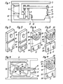
- the device has a frame 1, a load carrier 2 and a measuring system 3 attached to the frame 1.
- the load carrier is guided parallel and vertically by means of links 4.
- a lever 6 is pivotally mounted on a carrier 5 of the frame 1.
- the lever 6 is connected to the load carrier 2 at its left end. It acts on the entrance of the measuring system 3 via a stilt 7 attached to its right end.
- the lever 6 is provided with two disks 8 and 9.
- the disc 8 (Fig. 2) consists of a flat, substantially rectangular plate with an upper bore 10, two lower, preferably threaded bores 11 and two vertical Band joint 12 forming, horizontally arranged grooves.
- the disc 8 is rotatably and non-displaceably mounted on the lever 6 via the bore 10, ie in the so-called press fit. It is attached to the support 5 of the frame 1 by means of screws 13.
- the disk 9 (FIG. 3) is designed like the disk 8, but has a second hinge 14. The distance between the band joints 12 and the center of the bore 10 is the same for both disks 8, 9.
- the disk 9 is seated on the lever 6 in a rotationally and displaceably fixed manner. It is fastened to the load carrier 3 by means of screws 15.
- the stilt 7 has two tapers 16, 17 each forming a joint. It is attached to the lever 6 at its upper end and to the input of the measuring system 3 at its lower end. It thus acts as a pull rod.
- the taper 16 is arranged such that its distance from the longitudinal axis of the lever 6 is the same as the distance from the hinge 12 to the center of the bore 10.
- the device described works as follows. If a mass is placed on the load carrier 2, its weight is transferred to the lever 6 via the disk 9 acting as a tension element.
- the ligament joint 12 acts as the primary joint and the ligament joint 14 acts as the secondary joint.
- the lever 6 is pivoted about the hinge 12 of the disc 8. This is, of course, a virtual pan.
- the stilt 7 transmits the so-called measuring force to the measuring system 3.
- the taper 16 acts as the primary joint, the taper 17 as the secondary joint.
- FIGS. 4, 5 shows a variant of the design of the disks according to FIGS. 2, 3.
- a semicircular slot 18 is provided at the upper end of the disks 8, 9.
- Two horizontal grooves are provided on each side of the slot 18, which form two hinge joints 19, 20.
- This hinge pair 19, 20 corresponds to the hinge 12 of FIGS. 2, 3, but is located in the horizontal plane through the longitudinal axis of the lever 6.
- the second hinge 14 of the disk 9 of FIG. 3, which acts as a secondary joint, is in the embodiment of FIG Fig. 5 replaced by a tongue-shaped hinge 21, which has an 'increased flexibility with respect to bending and torsional moments.
- the lower part of both disks 8, 9 according to FIGS. 4, 5 has a thickness reduced by half from paragraph 22.
- the plane 23 of these lower parts runs through the center of the band joints 19, 20 or 19, 20 and 21. It goes without saying that the disks 8, 9 could be exchanged for one another.
- the measuring system 3 is attached to an arm 25 of the load carrier 2.
- the lever 6 is provided with two disks 26. It is connected to the frame 1 by means of the first disc 26. It is connected to the load carrier 2 via the second disk 26. In this embodiment, both disks 26 are identical.
- the right end of the lever 6 (as seen in FIG. 6) is connected to the measuring system 3 via a stilt 7, which is shown schematically and acts as a push rod.
- the slot 18 of the embodiment according to FIGS. 4, 5 is no longer semicircular in the case of the disk 26, but almost completely circular, so that the tongue 27 which acts as a primary joint has a width which essentially corresponds to the thickness of the disk 26.
- the slot 18 and the bore 10 are concentric.
- the remaining elements are as described with reference to FIG. 4.
- the tongue 27 could possibly also be designed like the joint 21 (FIG. 5), i.e. be thinner than the disk 26 itself.
- the ligament joints 12, 14, 19, 20 lie in the middle plane of the disks. But they could also be arranged offset with respect to this plane, whereby the length of the effective input arm of the lever 6 can be reduced.
Landscapes
- Physics & Mathematics (AREA)
- General Physics & Mathematics (AREA)
- Force Measurement Appropriate To Specific Purposes (AREA)
- Measurement Of Force In General (AREA)
- Testing Of Balance (AREA)
- Investigating Strength Of Materials By Application Of Mechanical Stress (AREA)
Priority Applications (6)
| Application Number | Priority Date | Filing Date | Title |
|---|---|---|---|
| EP85810127A EP0195876B1 (fr) | 1985-03-25 | 1985-03-25 | Dispositif pour mesurer une masse et une force |
| DE8585810127T DE3568083D1 (en) | 1985-03-25 | 1985-03-25 | Mass and force measuring device |
| AT85810127T ATE40600T1 (de) | 1985-03-25 | 1985-03-25 | Massen- und kraftmessgeraet. |
| US06/841,956 US4703816A (en) | 1985-03-25 | 1986-03-20 | Mass-measuring and force-measuring device |
| JP61064288A JPS61262620A (ja) | 1985-03-25 | 1986-03-24 | 質量及び力計測装置 |
| CA000504963A CA1269863A (fr) | 1985-03-25 | 1986-03-25 | Dispositif mesureur de masse et de force |
Applications Claiming Priority (1)
| Application Number | Priority Date | Filing Date | Title |
|---|---|---|---|
| EP85810127A EP0195876B1 (fr) | 1985-03-25 | 1985-03-25 | Dispositif pour mesurer une masse et une force |
Publications (2)
| Publication Number | Publication Date |
|---|---|
| EP0195876A1 true EP0195876A1 (fr) | 1986-10-01 |
| EP0195876B1 EP0195876B1 (fr) | 1989-02-01 |
Family
ID=8194634
Family Applications (1)
| Application Number | Title | Priority Date | Filing Date |
|---|---|---|---|
| EP85810127A Expired EP0195876B1 (fr) | 1985-03-25 | 1985-03-25 | Dispositif pour mesurer une masse et une force |
Country Status (6)
| Country | Link |
|---|---|
| US (1) | US4703816A (fr) |
| EP (1) | EP0195876B1 (fr) |
| JP (1) | JPS61262620A (fr) |
| AT (1) | ATE40600T1 (fr) |
| CA (1) | CA1269863A (fr) |
| DE (1) | DE3568083D1 (fr) |
Cited By (2)
| Publication number | Priority date | Publication date | Assignee | Title |
|---|---|---|---|---|
| DE3741409A1 (de) * | 1986-12-16 | 1988-06-30 | Wirth Gallo Messtechnik | Waage |
| WO1990001147A1 (fr) * | 1988-07-18 | 1990-02-08 | Wirth, Gallo Messtechnik Ag | Appareil de mesure de masse et de forces |
Families Citing this family (7)
| Publication number | Priority date | Publication date | Assignee | Title |
|---|---|---|---|---|
| CH673531A5 (fr) * | 1987-08-08 | 1990-03-15 | Wirth Gallo Messtechnik | |
| ATE131603T1 (de) * | 1990-09-21 | 1995-12-15 | Nuyts Orb Nv | Mobiles gerät zum wiegen einer ladung |
| CH687103A5 (de) * | 1993-08-20 | 1996-09-13 | Mettler Toledo Ag | Flache einstueckige Messaite mit zwei Knoten zur Weg- oder Kraftmessung. |
| JP2003083707A (ja) * | 2001-09-14 | 2003-03-19 | Matsushita Electric Ind Co Ltd | 歪センサ |
| GB201521633D0 (en) | 2015-12-08 | 2016-01-20 | Saifa Technology Ltd | Cash drawer |
| DE102023005463B4 (de) | 2023-06-29 | 2025-12-31 | Sartorius Lab Instruments Gmbh & Co. Kg | Wägesystem und Koppelband |
| DE102023117237A1 (de) * | 2023-06-29 | 2025-01-02 | Sartorius Lab Instruments Gmbh & Co. Kg | Wägesystem und Koppelband |
Citations (6)
| Publication number | Priority date | Publication date | Assignee | Title |
|---|---|---|---|---|
| US3423999A (en) * | 1964-11-27 | 1969-01-28 | Wirth Gallo & Co | Combined electronic mass and force meter |
| US4088198A (en) * | 1975-06-26 | 1978-05-09 | Wirth, Gallo & Co. | Load lever |
| EP0003222A2 (fr) * | 1978-01-26 | 1979-08-08 | WIRTH, GALLO & CO | Appareil de mesure des masses et des forces |
| EP0003473A1 (fr) * | 1978-02-02 | 1979-08-22 | WIRTH, GALLO & CO | Appareil de mesure des masses et des forces |
| DE2744328B2 (de) * | 1977-09-01 | 1979-09-27 | Wirth, Gallo & Co, Zuerich (Schweiz) | Massen- und Kraftmeßgerät |
| GB2142430A (en) * | 1983-06-30 | 1985-01-16 | Shinko Denshi Kk | Mechanism for converting weight into frequency |
Family Cites Families (3)
| Publication number | Priority date | Publication date | Assignee | Title |
|---|---|---|---|---|
| US3148742A (en) * | 1962-02-02 | 1964-09-15 | Illumitronic Systems Corp | Weighing cell |
| US3387679A (en) * | 1966-12-02 | 1968-06-11 | Icore Ind | Scale preloading mechanism |
| CH652207A5 (de) * | 1981-09-02 | 1985-10-31 | Mettler Instrumente Ag | Biegekoppel fuer waagen. |
-
1985
- 1985-03-25 DE DE8585810127T patent/DE3568083D1/de not_active Expired
- 1985-03-25 EP EP85810127A patent/EP0195876B1/fr not_active Expired
- 1985-03-25 AT AT85810127T patent/ATE40600T1/de not_active IP Right Cessation
-
1986
- 1986-03-20 US US06/841,956 patent/US4703816A/en not_active Expired - Fee Related
- 1986-03-24 JP JP61064288A patent/JPS61262620A/ja active Granted
- 1986-03-25 CA CA000504963A patent/CA1269863A/fr not_active Expired
Patent Citations (6)
| Publication number | Priority date | Publication date | Assignee | Title |
|---|---|---|---|---|
| US3423999A (en) * | 1964-11-27 | 1969-01-28 | Wirth Gallo & Co | Combined electronic mass and force meter |
| US4088198A (en) * | 1975-06-26 | 1978-05-09 | Wirth, Gallo & Co. | Load lever |
| DE2744328B2 (de) * | 1977-09-01 | 1979-09-27 | Wirth, Gallo & Co, Zuerich (Schweiz) | Massen- und Kraftmeßgerät |
| EP0003222A2 (fr) * | 1978-01-26 | 1979-08-08 | WIRTH, GALLO & CO | Appareil de mesure des masses et des forces |
| EP0003473A1 (fr) * | 1978-02-02 | 1979-08-22 | WIRTH, GALLO & CO | Appareil de mesure des masses et des forces |
| GB2142430A (en) * | 1983-06-30 | 1985-01-16 | Shinko Denshi Kk | Mechanism for converting weight into frequency |
Cited By (4)
| Publication number | Priority date | Publication date | Assignee | Title |
|---|---|---|---|---|
| DE3741409A1 (de) * | 1986-12-16 | 1988-06-30 | Wirth Gallo Messtechnik | Waage |
| US4844192A (en) * | 1986-12-16 | 1989-07-04 | Wirth Gallo Messtechnik Ag | Scale |
| WO1990001147A1 (fr) * | 1988-07-18 | 1990-02-08 | Wirth, Gallo Messtechnik Ag | Appareil de mesure de masse et de forces |
| US5078015A (en) * | 1988-07-18 | 1992-01-07 | Wirth Gallo Messtechnik Ag | Balance and dynamometer |
Also Published As
| Publication number | Publication date |
|---|---|
| US4703816A (en) | 1987-11-03 |
| DE3568083D1 (en) | 1989-03-09 |
| EP0195876B1 (fr) | 1989-02-01 |
| JPS61262620A (ja) | 1986-11-20 |
| CA1269863A (fr) | 1990-06-05 |
| ATE40600T1 (de) | 1989-02-15 |
| JPH0533730B2 (fr) | 1993-05-20 |
Similar Documents
| Publication | Publication Date | Title |
|---|---|---|
| DE2160278C2 (de) | Selbstnachstellende Betätigungsvorrichtung für eine Kraftfahrzeugkupplung | |
| DE4020299C2 (de) | Spiegelhaltevorrichtung | |
| EP0016238A1 (fr) | Dispositif de mesure des masses et des forces | |
| EP0195876B1 (fr) | Dispositif pour mesurer une masse et une force | |
| EP0071652A1 (fr) | Appareil de mesure de masses et de forces | |
| EP0025807A1 (fr) | Dispositif de mesure de masses et de forces | |
| DE2121357B2 (de) | Lastmessvorrichtung | |
| DE2755311A1 (de) | Seillast-messvorrichtung | |
| EP0046462A1 (fr) | Appareil pour la mesure des masses et des forces | |
| DE60211116T2 (de) | Ausgleichsmechanismus | |
| CH693154A5 (de) | Vorrichtung zur Ermittlung der Lage des Schwerpunktes eines Prüfkörpers. | |
| DE2522414C3 (de) | Auszugsvorrichtung für Schubfächer und Auszugsschränke | |
| DE2726869B2 (de) | Bandwaage | |
| DE2857525A1 (de) | Massen- und kraftmesser | |
| EP0156931B1 (fr) | Appareil de mesure de masse et de force | |
| EP0496969A2 (fr) | Dispositif de mesure des forces et couples dans un arrangement de joint | |
| DE10253060B4 (de) | Doppelachse | |
| DE857264C (de) | Fangvorrichtung fuer Aufzuege | |
| EP0115741A1 (fr) | Appareil pour mesurer des masses et des forces | |
| DE2552855C3 (de) | Einrichtung zum Steuern einer Druckluftbremse in Abhängigkeit von der Fahrzeugbelastung, insbesondere eines Schienenfahrzeuges | |
| DE2610716A1 (de) | Pruefvorrichtung der klemmkraft von seilklemmen | |
| DE3210047C2 (fr) | ||
| DE973029C (de) | Gleitsicherungsring fuer Ausbaurahmen aus ineinander gelegten rinnenfoermigen Profilen | |
| DE3938986C1 (en) | Chain attachment component - has spring which forms part of load and/or limit load warning indicator | |
| CH671100A5 (fr) |
Legal Events
| Date | Code | Title | Description |
|---|---|---|---|
| PUAI | Public reference made under article 153(3) epc to a published international application that has entered the european phase |
Free format text: ORIGINAL CODE: 0009012 |
|
| AK | Designated contracting states |
Kind code of ref document: A1 Designated state(s): AT BE CH DE FR GB IT LI NL SE |
|
| 17P | Request for examination filed |
Effective date: 19861004 |
|
| 17Q | First examination report despatched |
Effective date: 19871023 |
|
| GRAA | (expected) grant |
Free format text: ORIGINAL CODE: 0009210 |
|
| AK | Designated contracting states |
Kind code of ref document: B1 Designated state(s): AT BE CH DE FR GB IT LI NL SE |
|
| PG25 | Lapsed in a contracting state [announced via postgrant information from national office to epo] |
Ref country code: IT Free format text: LAPSE BECAUSE OF FAILURE TO SUBMIT A TRANSLATION OF THE DESCRIPTION OR TO PAY THE FEE WITHIN THE PRESCRIBED TIME-LIMIT;WARNING: LAPSES OF ITALIAN PATENTS WITH EFFECTIVE DATE BEFORE 2007 MAY HAVE OCCURRED AT ANY TIME BEFORE 2007. THE CORRECT EFFECTIVE DATE MAY BE DIFFERENT FROM THE ONE RECORDED. Effective date: 19890201 Ref country code: NL Effective date: 19890201 Ref country code: SE Effective date: 19890201 Ref country code: BE Effective date: 19890201 |
|
| REF | Corresponds to: |
Ref document number: 40600 Country of ref document: AT Date of ref document: 19890215 Kind code of ref document: T |
|
| GBT | Gb: translation of ep patent filed (gb section 77(6)(a)/1977) | ||
| REF | Corresponds to: |
Ref document number: 3568083 Country of ref document: DE Date of ref document: 19890309 |
|
| ET | Fr: translation filed | ||
| PG25 | Lapsed in a contracting state [announced via postgrant information from national office to epo] |
Ref country code: AT Effective date: 19890325 |
|
| NLV1 | Nl: lapsed or annulled due to failure to fulfill the requirements of art. 29p and 29m of the patents act | ||
| PLBE | No opposition filed within time limit |
Free format text: ORIGINAL CODE: 0009261 |
|
| STAA | Information on the status of an ep patent application or granted ep patent |
Free format text: STATUS: NO OPPOSITION FILED WITHIN TIME LIMIT |
|
| 26N | No opposition filed | ||
| REG | Reference to a national code |
Ref country code: CH Ref legal event code: NV Representative=s name: DR. REINHOLD C. SALGO PATENTANWALT |
|
| REG | Reference to a national code |
Ref country code: GB Ref legal event code: 732E |
|
| REG | Reference to a national code |
Ref country code: CH Ref legal event code: PUE Owner name: K-TRON PATENT AG C/O DR. HANS-JUERG SCHUERMANN -DA |
|
| REG | Reference to a national code |
Ref country code: FR Ref legal event code: TP |
|
| REG | Reference to a national code |
Ref country code: GB Ref legal event code: IF02 |
|
| PGFP | Annual fee paid to national office [announced via postgrant information from national office to epo] |
Ref country code: GB Payment date: 20040319 Year of fee payment: 20 |
|
| PGFP | Annual fee paid to national office [announced via postgrant information from national office to epo] |
Ref country code: FR Payment date: 20040329 Year of fee payment: 20 |
|
| PGFP | Annual fee paid to national office [announced via postgrant information from national office to epo] |
Ref country code: CH Payment date: 20040401 Year of fee payment: 20 |
|
| PGFP | Annual fee paid to national office [announced via postgrant information from national office to epo] |
Ref country code: DE Payment date: 20040504 Year of fee payment: 20 |
|
| PG25 | Lapsed in a contracting state [announced via postgrant information from national office to epo] |
Ref country code: GB Free format text: LAPSE BECAUSE OF EXPIRATION OF PROTECTION Effective date: 20050324 Ref country code: LI Free format text: LAPSE BECAUSE OF EXPIRATION OF PROTECTION Effective date: 20050324 Ref country code: CH Free format text: LAPSE BECAUSE OF EXPIRATION OF PROTECTION Effective date: 20050324 |
|
| REG | Reference to a national code |
Ref country code: GB Ref legal event code: PE20 |
|
| REG | Reference to a national code |
Ref country code: CH Ref legal event code: PL |