EP0195908A2 - Elastische Profilleiste - Google Patents
Elastische Profilleiste Download PDFInfo
- Publication number
- EP0195908A2 EP0195908A2 EP86101620A EP86101620A EP0195908A2 EP 0195908 A2 EP0195908 A2 EP 0195908A2 EP 86101620 A EP86101620 A EP 86101620A EP 86101620 A EP86101620 A EP 86101620A EP 0195908 A2 EP0195908 A2 EP 0195908A2
- Authority
- EP
- European Patent Office
- Prior art keywords
- profile
- legs
- strip
- elastic
- switching strip
- Prior art date
- Legal status (The legal status is an assumption and is not a legal conclusion. Google has not performed a legal analysis and makes no representation as to the accuracy of the status listed.)
- Granted
Links
- 239000011888 foil Substances 0.000 claims description 4
- 230000003014 reinforcing effect Effects 0.000 claims description 3
- 230000007704 transition Effects 0.000 claims description 3
- 238000005299 abrasion Methods 0.000 claims description 2
- 239000002184 metal Substances 0.000 claims description 2
- 238000000926 separation method Methods 0.000 claims description 2
- 239000000126 substance Substances 0.000 claims description 2
- 238000005452 bending Methods 0.000 claims 1
- 238000004519 manufacturing process Methods 0.000 description 2
- 230000005540 biological transmission Effects 0.000 description 1
- 239000004020 conductor Substances 0.000 description 1
- 238000010276 construction Methods 0.000 description 1
- 230000001771 impaired effect Effects 0.000 description 1
- 238000003780 insertion Methods 0.000 description 1
- 230000037431 insertion Effects 0.000 description 1
- 239000011810 insulating material Substances 0.000 description 1
- 238000000034 method Methods 0.000 description 1
- 229920006267 polyester film Polymers 0.000 description 1
- 238000005096 rolling process Methods 0.000 description 1
- 210000002105 tongue Anatomy 0.000 description 1
- 230000001960 triggered effect Effects 0.000 description 1
Images


Classifications
-
- H—ELECTRICITY
- H01—ELECTRIC ELEMENTS
- H01H—ELECTRIC SWITCHES; RELAYS; SELECTORS; EMERGENCY PROTECTIVE DEVICES
- H01H3/00—Mechanisms for operating contacts
- H01H3/02—Operating parts, i.e. for operating driving mechanism by a mechanical force external to the switch
- H01H3/14—Operating parts, i.e. for operating driving mechanism by a mechanical force external to the switch adapted for operation by a part of the human body other than the hand, e.g. by foot
- H01H3/141—Cushion or mat switches
- H01H3/142—Cushion or mat switches of the elongated strip type
-
- E—FIXED CONSTRUCTIONS
- E05—LOCKS; KEYS; WINDOW OR DOOR FITTINGS; SAFES
- E05F—DEVICES FOR MOVING WINGS INTO OPEN OR CLOSED POSITION; CHECKS FOR WINGS; WING FITTINGS NOT OTHERWISE PROVIDED FOR, CONCERNED WITH THE FUNCTIONING OF THE WING
- E05F15/00—Power-operated mechanisms for wings
- E05F15/40—Safety devices, e.g. detection of obstructions or end positions
- E05F15/42—Detection using safety edges
- E05F15/44—Detection using safety edges responsive to changes in electrical conductivity
-
- E—FIXED CONSTRUCTIONS
- E05—LOCKS; KEYS; WINDOW OR DOOR FITTINGS; SAFES
- E05Y—INDEXING SCHEME ASSOCIATED WITH SUBCLASSES E05D AND E05F, RELATING TO CONSTRUCTION ELEMENTS, ELECTRIC CONTROL, POWER SUPPLY, POWER SIGNAL OR TRANSMISSION, USER INTERFACES, MOUNTING OR COUPLING, DETAILS, ACCESSORIES, AUXILIARY OPERATIONS NOT OTHERWISE PROVIDED FOR, APPLICATION THEREOF
- E05Y2600/00—Mounting or coupling arrangements for elements provided for in this subclass
- E05Y2600/40—Mounting location; Visibility of the elements
-
- E—FIXED CONSTRUCTIONS
- E05—LOCKS; KEYS; WINDOW OR DOOR FITTINGS; SAFES
- E05Y—INDEXING SCHEME ASSOCIATED WITH SUBCLASSES E05D AND E05F, RELATING TO CONSTRUCTION ELEMENTS, ELECTRIC CONTROL, POWER SUPPLY, POWER SIGNAL OR TRANSMISSION, USER INTERFACES, MOUNTING OR COUPLING, DETAILS, ACCESSORIES, AUXILIARY OPERATIONS NOT OTHERWISE PROVIDED FOR, APPLICATION THEREOF
- E05Y2900/00—Application of doors, windows, wings or fittings thereof
- E05Y2900/10—Application of doors, windows, wings or fittings thereof for buildings or parts thereof
- E05Y2900/13—Type of wing
- E05Y2900/132—Doors
Definitions
- the invention relates to an elastic profile strip according to the preamble of claim 1.
- the aim of the invention is to provide an elastic profile strip of the type mentioned, which is particularly simple in construction with a simple possibility of manufacture and nevertheless with all occurring stresses, i.e. both in the case of centrally and laterally acting forces, the contact strip is made safe and quickly.
- the cavity which is present in the elastic profile and which is essentially triangular in cross section is largely fully utilized for accommodating the intermediate profile, which in turn contains the electrical safety edge.
- the changes in curvature of the side surfaces that occur when the elastic profile is deformed are passed on to one of the legs of the intermediate profile, which is then deformed so that the associated actuation projection presses essentially from above onto the switching strip and deforms it so that contact is reliably made.
- a response is largely independent of the direction from which the profile strip is loaded.
- a preferred embodiment is characterized in that the actuating ribs are at a short distance from the switching strip. In this way it is ensured that not every slight touch of the hollow profile leads to making contact, but that certain paths have to be covered before the contact strips in the switching strip touch.
- a preferred embodiment is characterized in that, in the normal state, at most the outer ends of the legs of the intermediate profile touch the side surfaces of the profile, preferably leaving a slight distance, in particular up to about 2 mm.
- the design should be such that the base piece is laterally spaced from the legs.
- the outer ends of the webs center the intermediate profile lying against the base with the base piece.
- the insertion of the intermediate profile into the cavity is possible with little effort, because the legs, which are clearly spaced apart, give way slightly inwards by springs and can thus be drawn into the elastic profile with only slight frictional resistance.
- the intermediate profile nevertheless assumes a defined position within the elastic profile, because the webs rebound and thus take over the securing of the position of the intermediate profile in the cavity of the elastic outer profile.
- the above-described function is not impaired if the intermediate profile can be displaced to a small extent from the central position on both sides, which is possible if the outer ends of the legs of the intermediate profile are at a short distance of up to 2 mm from the side faces.
- the legs in the area of the switching strip are at a clear angle of preferably 30 to 60 °, in particular approximately 40 to 50 °, from the base Extend piece to above the safety edge and bend there, forming the actuating ribs, in a direction essentially perpendicular to the base piece and preferably bend it.
- legs have a concave curved outer surface, preferably similar to the curvature of the side surfaces in the undeformed state.
- the intermediate profile serves at the same time to carry the profile strip, which is preferably glued to the base piece, to form the actuating ribs for the switching strip and to form the actuating end pieces of the legs.
- An advantageous development of the invention is characterized in that friction and abrasion-reducing foils are arranged between the legs and the switching strip.
- the films should be glued to the legs.
- a further embodiment is designed such that axial, preferably inwardly open channels are provided in the transition area from the base piece to the legs, in which reinforcing wires are arranged.
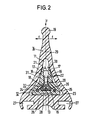
- an elastic profile 14 made of rubber for example, has an essentially triangular cross section, but the side faces 17 of the profile 14 according to FIG. 2 are slightly curved inwards, so that when the profile is bent in the direction of one of the arrows f in FIG. 2, the respectively assigned side surface 17 is more strongly arched and the opposite side surface 17 is stretched somewhat more. Due to the special triangular design of the profile 14, a bend in the direction of one of the arrows f also takes place when the profile 14 is stressed in the direction of arrow F from the opening to be closed. The bead-like triangular tip 19 of the elastic profile 14 facing the opening to be closed is then laterally deflected either in the direction of one or the other arrow f.
- the elastic profile 14 has a base 26, which in a suitable manner, e.g. can be fastened by means of the grooves 27 to the closing edge, for example a door or a rolling gate.
- an elastic intermediate profile 12 designed according to the invention is drawn, which can also be made of rubber.
- the elastic intermediate profile 12 has an elongated and essentially flat base piece 15, which lies flat against the base 13 of the cavity 11.
- the flat base piece 15 has an elongated depression 28, which has the purpose of making the intermediate profile 12 as flexible as possible.
- the two outer surfaces of the legs 16 of the intermediate profile 12 could also have a circular concave curvature, as is indicated by the dash-dotted line 31 'in FIG. 3.
- an electrical switching strip 18 is arranged in the middle, which consists of an elastic hollow profile 32, which has a flat base side and a semi-cylindrical actuating side, from which a switching rib 33 extends to the flat base area, on which an elastic pair of contact strips 34 is attached, which consists of two resilient metal strips held at a distance by an insulating material.
- the electrical safety edge 18 is of the same design as that described in the published documents 32 32 365 and 33 12 223.
- actuating ribs 20 are formed at a short distance from the electrical switching strip 18 and are located substantially slightly above the electrical switching strip 18.
- the outer ends 21 of the legs 16 lie against the inside of the side surfaces 17 of the elastic profile 14.
- an abrasion and friction-resistant polyester film 22 is inserted between the legs 16 and the electrical switching strip 18, which is preferably glued to the legs 16.
- the film also serves for the chemical separation between the hollow profile 32 made of PVC and the intermediate profile 12 made of rubber.
- axial reinforcing wires 25 In the transition area between the base piece 15 and the legs 16, approximately three-quarter circular axial longitudinal channels 24 are provided on the inside in the intermediate profile 12, in which, according to FIG. 2, axial reinforcing wires 25 can be arranged. From the base piece 15, around the lower longitudinal regions of the switching strip 18, there extend clamping tongues 35 which hold the switching strip 18 securely, which should additionally be glued in.
- the intermediate profile 12 is shaped such that it only touches the inner walls of the cavity 11 with the lower surface of the base piece 15 and the ends 21 of the legs 16.
- the cavity 11 is then closed at one end by a plug 36, while the electrical connection 37 is inserted from the other end, a closure piece 38 likewise being provided in this area.
- the edge 19 in any case deviates in the direction of one of the arrows f, ie laterally, whereupon the associated side surface 17 of the elastic profile 14 assumes a greater curvature and the associated leg 16 presses inwards by reducing the distance A.
- the actuating ribs 20 pivot essentially around the connection point with the base piece 15 and press in Fig. 2, 3 essentially from above onto the switching strip 18, whereupon the actuating rib 33 acts on the contact band pair 34 and brings about an electrical contact. A switching signal is thus triggered in a simple and safe manner.
- the safety edge 18 there is therefore an intermediate profile 12 which can be inserted into the profile 14 and which, owing to the delta-shaped cross section, transmits an easy and reliable switching operation to the safety edge 18. Since the delta-shaped outer contour of the profile 14 has to buckle with every load, the lateral curvature of this profile 14 is always transferred to the intermediate profile 12. The transmission of the forces from the intermediate profile 12 to the switching strip 18 takes place via a lever arm. This produces a switching process with very little force.
- the intermediate profile 12 is designed so that the elongated legs 16 absorb the bulge of the profile 14 and thus act on the safety edge 18 essentially from above.
Landscapes
- Push-Button Switches (AREA)
- Fittings On The Vehicle Exterior For Carrying Loads, And Devices For Holding Or Mounting Articles (AREA)
- Polishing Bodies And Polishing Tools (AREA)
- Ultra Sonic Daignosis Equipment (AREA)
- Power-Operated Mechanisms For Wings (AREA)
- Crystals, And After-Treatments Of Crystals (AREA)
- Massaging Devices (AREA)
Abstract
Description
- Die Erfindung betrifft eine elastische Profilleiste nach dem Oberbegriff des Patentanspruchs 1.
- Es ist bereits bekannt, elastische Profilleisten mit wenigstens einem sich in ihrer Längsrichtung erstreckenden Hohlraum mit einer in dem Hohlraum angeordneten elektrischen Schaltleiste zu versehen, um bei Verformungen der Profilleiste einen Kontakt innerhalb der elektrischen Schaltleiste zu schließen und so ein elektrisches Warn- und/oder Stoppsignal für den Türantrieb auszulösen (DE-OS 32 32 365, DE-OS 33 12 223).
- Bei allen bekannten elektrischen Profilleisten müssen besondere Maßnahmen vorgesehen werden, um die elektrische Schaltleiste sowohl bei senkrecht auf die Schließkante wirkenden Kräften als auch bei bis um annähernd 90° dazu versetzten seitlichen Kräften so zu beaufschlagen, daß eine Kontaktgabe stattfindet. Hierzu ist teilweise die Anordnung von zwei Schaltleisten erforderlich oder es müssen besonders gestaltete Steganordnungen innerhalb der Profilleiste verwendet werden.
- Bei einer weiteren bekannten elektrischen Kontaktleiste (DE-OS 28 08 964) sind die Kontaktleiter unmittelbar an der Innenseite des Profils angeordnet, was eine sehr aufwendige Herstellung erfordert. Eine Kontaktgabe erfolgt nur bei seitlichen Beanspruchungen, nicht aber wenn eine Kraft zentral auf das Profil einwirkt. Für die Sicherung von Schließkanten ist diese Profilleiste also nicht verwendbar.
- Demgegenüber besteht das Ziel der Erfindung darin, eine elastische Profilleiste der eingangs genannten Gattung zu schaffen, welche bei einfacher Herstellmöglichkeit von besonders einfachem Aufbau ist und gleichwohl bei allen vorkommenden Beanspruchungen, d.h. sowohl bei zentral als auch bei seitlich angreifenden Kräften sicher und schnell eine Kontaktgabe der Schaltleiste bewirkt.
- Zur Lösung dieser Aufgabe sind die Merkmale des kennzeichnenden Teils des Patentanspruchs 1 vorgesehen.
- Erfindungsgemäß wird also der in dem elastischen Profil vorhandene, im Querschnitt im wesentlichen dreieckförmige Hohlraum weitgehend vollständig für die Unterbringung des Zwischenprofils ausgenutzt, welches seinerseits die elektrische Schaltleiste enthält. Die bei Verformungen des elastischen Profils auftretenden Wölbungsänderungen der Seitenflächen werden auf jeweils einen der Schenkel des Zwischenprofils weitergegeben, welches dann so verformt wird, daß der zugeordnete Betätigungsvorsprung im wesentlichen von oben auf die Schaltleiste drückt und diese so verformt, daß sicher eine Kontaktgabe erfolgt. Ein Ansprechen erfolgt weitgehend unabhängig von der Richtung, aus der die Beanspruchung der Profilleiste erfolgt.
- Eine bevorzugte Ausführungsform kennzeichnet sich dadurch, daß die Betätigungsrippen einen geringen Abstand von der Schaltleiste besitzen. Auf diese Weise wird gewährleistet, daß nicht schon jede geringfügige Berührung des Hohlprofils zu einer Kontaktgabe führt, sondern daß erst gewisse Wege zurückgelegt werden müssen, bevor die Kontaktbänder in der Schaltleiste sich berühren.
- Eine bevorzugte Ausführungsform kennzeichnet sich dadurch, daß im Normalzustand allenfalls die äußeren Enden der Schenkel des Zwischenprofils die Seitenflächen des Profils berühren, wobei bevorzugt ein geringfügiger Abstand insbesondere bis etwa 2 mm belassen wird. Insbesondere soll die Ausführung so sein, daß auch das Basisstück seitlich einen Abstand von den Schenkeln aufweist.
- Auf diese Weise zentrieren die äußeren Enden der Stege das mit dem Basisstück an der Grundfläche anliegende Zwischenprofil. Das Einbringen des Zwischenprofils in den Hohlraum ist mit geringem Kraftaufwand möglich, weil die einen deutlichen Abstand aufweisenden Schenkel durch Federn nach innen leicht nachgeben und so unter nur geringem Reibungswiderstand in das elastische Profil eingezogen werden können. Im eingezogenen Zustand nimmt das Zwischenprofil gleichwohl eine definierte Lage innerhalb des elastischen Profils an, weil die Stege wieder ausfedern und so die Lagesicherung des Zwischenprofils in dem Hohlraum des elastischen äußeren Profils übernehmen. Die vorstehend beschriebene Funktion wird nicht beeinträchtigt, wenn das Zwischenprofil in geringem Maße aus der Mittelposition nach beiden Seiten verschiebbar ist, was möglich ist, wenn die äußeren Enden der Schenkel des Zwischenprofils von den Seitenflächen einen geringen Abstand von bis zu 2 mm haben.
- Besonders bevorzugt ist es, wenn die Schenkel im Bereich der Schaltleiste sich unter einem deutlichen Winkel von vorzugsweise 30 bis 60°, insbesondere etwa 40 bis 50°, von dem Basisstück bis oberhalb der Schaltleiste erstreckeii und dort unter Bildung der Betätigungsrippen in eine im wesentlichen senkrecht zu dem Basisstück verlaufende Richtung abbiegen und vorzugsweise abknicken.
- Eine weitere Alternative besteht darin, daß die Schenkel eine konkave gekrümmte Außenfläche aufweisen, und zwar bevorzugt ähnlich der Wölbung der Seitenflächen im unverformten Zustand.
- Auf diese Weise dient das Zwischenprofil gleichzeitig zum Tragen der vorzugsweise an das Basisstück angeklebten Profilleiste zur Bildung der Betätigungsrippen für die Schaltleiste und zur Bildung der Betätigungsendstücke der Schenkel.
- Eine vorteilhafte Weiterbildung der Erfindung kennzeichnet sich dadurch, daß zwischen den Schenkeln und der Schaltleiste reibungs- und abriebmindernde Folien angeordnet sein. Insbesondere sollen die Folien an die Schenkel angeklebt sein.
- Zur Verstärkung des Zwischenprofils ist eine weitere Ausführungsform so ausgebildet, daß im Übergangsbereich vom Basisstück zu den Schenkeln axiale, vorzugsweise nach innen offene Kanäle vorgesehen sind, in denen Verstärkungsdrähte angeordnet sind.
- Die Erfindung wird im folgenden beispielsweise anhand der Zeichnung beschrieben; in dieser zeigt:
- Fig. 1 eine teilweise geschnittene Seitenansicht einer erfindungsgemäßen Profilleiste,
- Fig. 2 einen Schnitt nach Linie II-II in Fig. 1 und
- Fig. 3 einen vergrößerten Querschnitt des Zwischenprofils der erfindungsgemäßen Profilleiste.
- Nach der Zeichnung besitzt ein z.B.` aus Gummi bestehendes elastisches Profil 14 einen im wesentlichen dreieckförmigen Querschnitt, wobei jedoch die Seitenflächen 17 des Profils 14 gemäß Fig. 2 leicht nach innen gewölbt sind, so daß beim Abbiegen des Profils in Richtung eines der Pfeile f in Fig. 2 die jeweils zugeordnete Seitenfläche 17 stärker gewölbt und die entgegengesetzte Seitenfläche 17 etwas mehr gestreckt wird. Aufgrund der speziellen dreieckförmigen Ausbildung des Profils 14 erfolgt eine Abbiegung in Richtung eines der Pfeile f auch dann, wenn das Profil 14 von der zu verschließenden öffnung her in Richtung des Pfeiles F beansprucht wird. Die der zu verschließenden Öffnung zugewandte wulstartige Dreiecksspitze 19 des elastischen Profils 14 wird dann entweder in Richtung des einen oder des anderen Pfeiles f seitlich ausgelenkt.
- An dem von der wulstartigen Dreiecksspitze 19 abgewandten Ende weist das elastische Profil 14 einen Sockel 26 auf, der in geeigneter Weise, z.B. mittels der Nuten 27 an der Schließkante beispielsweise einer Tür oder eines Rolltors befestigt werden kann.
- Innerhalb des elastischen Profils 14 befindet sich ein entsprechend im Querschnitt annähernd dreiecksförmiger Hohlraum 11, in den ein gemäß der Erfindung ausgebildetes elastisches Zwischenprofil 12 eingezogen ist, welches ebenfalls aus Gummi hergestellt sein kann.
- Das elastische Zwischenprofil 12 weist ein längliches und im wesentlichen flaches Basisstück 15 auf, welches flach an der Grundfläche 13 des Hohlraumes 11 anliegt. Im mittleren Bereich weist das flache Basisstück 15 eine längliche Einsenkung 28 auf, welche den Zweck hat, das Zwischenprofil 12 möglichst flexibel zu gestalten.
- Von den beiden Seiten des Basisstückes 15 aus erstrecken sich in Richtung zur wulstartigen Dreiecksspitze 19 des elastischen Profils 14 zwei Schenkel 16, die zunächst unter einem Winkel von 30° und dann unter einem Winkel von 45° zur Mittellängsebene 29 des elastischen Profils 14 verlaufen und dann praktisch senkrecht zum Basisstück 15 in Richtung der Kante 19 abknicken. Die Innenflächen 30 des Endbereiches der Schenkel 16 sind genau senkrecht zum Basisstück 15, während die Außenflächen 31 einen Winkel von etwa 15° mit der Mittellängsachse 29 einschließen.
- Bei einer vorteilhaften alternativen Ausführung könnten die beiden Außenflächen der Schenkel 16 des Zwischenprofils 12 auch kreisförmig konkav gekrümmt sein, wie das durch die strichpunktierte Linie 31' in Fig. 3 angedeutet ist.
- Auf dem Basisstück 15 ist in der Mitte eine elektrische Schaltleiste 18 angeordnet, welche aus einem elastischen Hohlprofil 32 besteht, das eine ebene Grundseite und eine halbzylindrisch ausgebildete Betätigungsseite aufweist, von der sich eine Schaltrippe 33 zu dem ebenen Grundbereich erstreckt, auf dem ein elastisches Kontaktbandpaar 34 angebracht ist, welches aus zwei durch ein Isoliermaterial auf Abstand gehaltenen federnden Blechbändern besteht. Die elektrische Schaltleiste 18 ist von gleicher Ausführung, wie dies in den Offenlegungsschriften 32 32 365 und 33 12 223 beschrieben ist.
- Durch das Abknicken der Schenkel 16 im Bereich unmittelbar oberhalb der elektrischen Schaltleiste 18 entstehen in geringem Abstand von der elektrischen Schaltleiste 18 Betätigungsrippen 20, die sich im wesentlichen geringfügig oberhalb der elektrischen Schaltleiste 18 befinden.
- Nach Fig. 2 liegen die äußeren Enden 21 der Schenkel 16 innen an den Seitenflächen 17 des elastischen Profils 14 an.
- Nach Fig. 2 ist zwischen den Schenkeln 16 und der elektrischen Schaltleiste 18 jeweils eine abrieb- und reibungsfeste Polyesterfolie 22 eingelegt, die vorzugsweise an die Schenkel 16 angeklebt ist. Die Folie dient auch der chemischen Trennung zwischen dem aus PVC bestehenden Hohlprofil 32 und dem aus Gummie bestehenden Zwischenprofil 12.
- Im Übergangsbereich zwischen dem Basisstück 15 und den Schenkeln 16 sind in dem Zwischenprofil 12 innen etwa dreiviertelkreisförmige axiale Längskanäle 24 vorgesehen, in denen nach Fig. 2 axiale Verstärkungsdrähte 25 angeordnet sein können. Vom Basisstück 15 erstrecken sich um die unteren Längsbereiche der Schaltleiste 18 herum Klemmzungen 35, welche die Schaltleiste 18 sicher halten, die zusätzlich eingeklebt sein soll.
- Zwischen den Schenkeln 16 befindet sich ein deutlicher Abstand A, wie er für eine zwanglose Betätigung der Schaltleiste 18 erforderlich ist. Nach Fig. 2 ist das Zwischenprofil 12 so geformt, daß es lediglich mit der unteren Fläche des Basisstückes 15 und den Enden 21 der Schenkel 16 die Innenwände des Hohlraums 11 berührt.
- Die Montage und die Arbeitsweise der erfindungsgemäßen Profilleiste sind wie folgt:
- Nach dem Einkleben der elektrischen Schaltleiste 18 in das Zwischenprofil 12 unter Anordnung der Folien 22 wird das die elektrische Schaltleiste 18 enthaltende Zwischenprofil 12 axial in den Hohlraum 11 des elastischen Profil 14 eingezogen, was zwanglos möglich ist, weil die Schenkel 16 unter Verringerung des Abstandes A hierbei elastisch nach innen nachgeben können.
- Am einen Ende wird dann der Hohlraum 11 durch einen Stopfen 36 verschlossen, während vom anderen Ende her der elektrische Anschluß 37 eingeführt wird, wobei in diesem Bereich ebenfalls ein Verschlußstück 38 vorgesehen ist.
- Schließlich wird das elastische Profil 14 an der Schließkante einer Tür o.dgl. befestigt.
- Wirken jetzt aufgrund des Anstoßens der wulstartigen Kante 19 an ein Hindernis Kräfte auf das elastische Profil 14 in Richtung der Pfeile f oder F, so weicht die Kante 19 in jedem Fall in Richtung eines der Pfeile f, d.h. seitlich aus, worauf die zugeordnete Seitenfläche 17 des elastischen Profils 14 eine stärkere Wölbung annimmt und hierbei den zugeordneten Schenkel 16 unter Verkleinerung des Abstandes A nach innen drückt. Dadurch schwenken die Betätigungsrippen 20 im wesentlichen um die Verbindungsstelle mit dem Basisstück 15 herum und drücken in Fig. 2, 3 im wesentlichen von oben auf die Schaltleiste 18, worauf die Betätigungsrippe 33 das Kontaktbandpaar 34 beaufschlagt und einen elektrischen Kontakt herbeiführt. Es wird somit auf einfache und sichersWeise ein Schaltsignal ausgelöst.
- Für die Schaltleiste 18 liegt also ein in das Profil 14 einsetzbares Zwischenprofil 12 vor, welches aufgrund des deltaförmigen Querschnitts einen leichten und zuverlässigen Schaltvorgang auf die Schaltleiste 18 überträgt. Da die deltaförmige Außenkontur des Profils 14 bei jeder Belastung ausknicken muß, wird die seitliche Einwölbung dieses Profils 14 immer auf das Zwischenprofil 12 übertragen. Die Übertragung der Kräfte vom Zwischenprofil 12 auf die Schaltleiste 18 erfolgt über einen Hebelarm. Dadurch wird ein Schaltvorgang mit sehr geringer Kraft erzeugt. Das Zwischenprofil 12 ist so gestaltet, daß die verlängerten Schenkel 16 die Ausbeulung des Profils 14 aufnehmen und so die Schaltleiste 18 im wesentlichen von oben beaufschlagen.
Claims (9)
Priority Applications (1)
| Application Number | Priority Date | Filing Date | Title |
|---|---|---|---|
| AT86101620T ATE37582T1 (de) | 1985-03-25 | 1986-02-07 | Elastische profilleiste. |
Applications Claiming Priority (2)
| Application Number | Priority Date | Filing Date | Title |
|---|---|---|---|
| DE3510806A DE3510806C2 (de) | 1985-03-25 | 1985-03-25 | Elastische Profilleiste |
| DE3510806 | 1985-03-25 |
Publications (3)
| Publication Number | Publication Date |
|---|---|
| EP0195908A2 true EP0195908A2 (de) | 1986-10-01 |
| EP0195908A3 EP0195908A3 (en) | 1987-01-21 |
| EP0195908B1 EP0195908B1 (de) | 1988-09-28 |
Family
ID=6266290
Family Applications (1)
| Application Number | Title | Priority Date | Filing Date |
|---|---|---|---|
| EP86101620A Expired EP0195908B1 (de) | 1985-03-25 | 1986-02-07 | Elastische Profilleiste |
Country Status (5)
| Country | Link |
|---|---|
| US (1) | US4684768A (de) |
| EP (1) | EP0195908B1 (de) |
| AT (1) | ATE37582T1 (de) |
| DE (2) | DE3510806C2 (de) |
| FI (1) | FI81432C (de) |
Cited By (1)
| Publication number | Priority date | Publication date | Assignee | Title |
|---|---|---|---|---|
| EP0606589A1 (de) * | 1993-01-13 | 1994-07-20 | METEOR GUMMIWERKE K.H. BÄDJE GMBH & CO. | Sicherheitsschalter und Verfahren zu seiner Herstellung |
Families Citing this family (20)
| Publication number | Priority date | Publication date | Assignee | Title |
|---|---|---|---|---|
| DE3921533A1 (de) * | 1989-06-30 | 1991-01-03 | Karlheinz Beckhausen | Sicherheitskontaktschiene |
| DE4007271A1 (de) * | 1990-03-08 | 1991-09-12 | Hella Kg Hueck & Co | Sicherheitseinrichtung fuer einen antrieb eines beweglichen teils in einem kraftfahrzeug |
| US5066835A (en) * | 1990-09-19 | 1991-11-19 | Miller Edge, Inc. | Sensing edge |
| DE4029929C2 (de) * | 1990-09-21 | 1999-11-04 | G E K Ges Fuer Elektrotechnisc | Sicherheits-Schaltleiste |
| US5087799A (en) * | 1990-12-27 | 1992-02-11 | Techstrip Inc. | Power Door sensing strip |
| US5192381A (en) * | 1990-12-27 | 1993-03-09 | Techstrip Inc. | Power door sensing strip |
| US5157230A (en) * | 1991-03-11 | 1992-10-20 | Holmes-Hally Industries | Safety actuator apparatus for one-piece overhead garage door operator |
| US5260529A (en) * | 1991-07-19 | 1993-11-09 | Miller Edge, Inc. | Sensing edge for a door including a switch and flexible protruding sensing members |
| US5259143A (en) * | 1992-04-17 | 1993-11-09 | Wayne-Dalton Corp. | Astragal for closure members |
| DE4429325A1 (de) * | 1994-08-18 | 1996-02-22 | Bayerische Motoren Werke Ag | Sensoreinrichtung für Kraftfahrzeuge zur Einklemmerkennung |
| GB2301622B (en) * | 1995-06-02 | 1997-04-23 | Standard Prod Ltd | Anti-trap sealing device |
| US5589811A (en) * | 1995-06-22 | 1996-12-31 | Techstrip, Inc. | Power door safety sensing strip |
| DE29808292U1 (de) | 1998-05-07 | 1998-07-23 | Schieffer Tor- und Schutzsysteme GmbH, 59557 Lippstadt | Abschlußprofil für ein Torblatt |
| US6291957B1 (en) * | 1999-10-29 | 2001-09-18 | Meritor Light Vehicle Systems, Inc. | Obstruction sensing utilizing lateral forces on a moving window |
| US6689970B2 (en) * | 2001-10-04 | 2004-02-10 | Lester E. Burgess | Pressure actuated switching device and method and system for making same |
| DE102004009079B4 (de) * | 2004-02-25 | 2007-08-30 | Hübner GmbH | Fingerschutzprofil |
| DE102005060043B3 (de) * | 2005-12-15 | 2008-01-03 | Webasto Ag | Öffnungsfähiges Fahrzeugdach |
| US7476819B1 (en) * | 2007-01-25 | 2009-01-13 | Tapeswitch Corporation | Switch box for multi-directional activation of a ribbon switch |
| JP6516052B1 (ja) * | 2018-06-25 | 2019-05-22 | 日立金属株式会社 | 挟み込み検知センサ |
| JP7604913B2 (ja) * | 2021-01-28 | 2024-12-24 | 株式会社プロテリアル | 感圧センサ |
Family Cites Families (8)
| Publication number | Priority date | Publication date | Assignee | Title |
|---|---|---|---|---|
| DE1777379U (de) * | 1958-07-07 | 1958-11-13 | Herbert Smetana | Kotaktleiste. |
| US3118984A (en) * | 1961-04-12 | 1964-01-21 | Tapeswitch Corp Of America | Door edge switch means |
| US4115952A (en) * | 1977-03-02 | 1978-09-26 | American Can Company | Safety door edge |
| CH610140A5 (en) * | 1977-03-07 | 1979-03-30 | Weidmann S Hch Erben | Contact strip |
| DE2839498C2 (de) * | 1978-09-11 | 1980-10-16 | Donges Stahlbau Gmbh, 6100 Darmstadt | Kantenbesatz für den oder die Flügel eines kraftbetriebenen Großtores |
| EP0104414B1 (de) * | 1982-08-31 | 1987-05-06 | Erwin Sick GmbH Optik-Elektronik | Längliches, elastisches Türkantenprofil |
| DE3312223C2 (de) * | 1983-04-05 | 1987-04-23 | Erwin Sick Gmbh Optik-Elektronik, 7808 Waldkirch | Elastische Profilleiste an einer Schließkante einer Abdeckung |
| DE3232365C2 (de) * | 1982-08-31 | 1986-07-10 | Erwin Sick Gmbh Optik-Elektronik, 7808 Waldkirch | Elastisches Profil an der Schließkante einer Abdeckung |
-
1985
- 1985-03-25 DE DE3510806A patent/DE3510806C2/de not_active Expired
-
1986
- 1986-02-07 EP EP86101620A patent/EP0195908B1/de not_active Expired
- 1986-02-07 DE DE8686101620T patent/DE3660825D1/de not_active Expired
- 1986-02-07 AT AT86101620T patent/ATE37582T1/de not_active IP Right Cessation
- 1986-02-19 US US06/831,019 patent/US4684768A/en not_active Expired - Fee Related
- 1986-03-24 FI FI861240A patent/FI81432C/fi not_active IP Right Cessation
Cited By (1)
| Publication number | Priority date | Publication date | Assignee | Title |
|---|---|---|---|---|
| EP0606589A1 (de) * | 1993-01-13 | 1994-07-20 | METEOR GUMMIWERKE K.H. BÄDJE GMBH & CO. | Sicherheitsschalter und Verfahren zu seiner Herstellung |
Also Published As
| Publication number | Publication date |
|---|---|
| FI81432C (fi) | 1990-10-10 |
| DE3510806C2 (de) | 1986-11-27 |
| DE3660825D1 (en) | 1988-11-03 |
| US4684768A (en) | 1987-08-04 |
| ATE37582T1 (de) | 1988-10-15 |
| EP0195908A3 (en) | 1987-01-21 |
| FI81432B (fi) | 1990-06-29 |
| FI861240A0 (fi) | 1986-03-24 |
| FI861240L (fi) | 1986-09-26 |
| DE3510806A1 (de) | 1985-09-19 |
| EP0195908B1 (de) | 1988-09-28 |
Similar Documents
| Publication | Publication Date | Title |
|---|---|---|
| EP0195908B1 (de) | Elastische Profilleiste | |
| DE4309088C2 (de) | Ortsfest einbaubare Scheibe für Kraftfahrzeuge | |
| DE2735787A1 (de) | Fuehrungselement fuer nachgiebig zu lagernde schiebetuerelemente sowie damit ausgeruestetes schiebetuerelement | |
| DE69415333T2 (de) | Gegossene sicherheitsnadel | |
| DE2738672A1 (de) | Fensterheber, insbesondere fuer kraftfahrzeuge | |
| EP1876048B1 (de) | Fingerschutzleiste, insbesondere für Aussen- und Innenschwenktüren | |
| DE3232365C2 (de) | Elastisches Profil an der Schließkante einer Abdeckung | |
| DE2702470C3 (de) | Feststellvorichtung für eine Tür, insbesondere an Kraftfahrzeugen | |
| EP1354545B1 (de) | Dichtung für eine Duschabtrennung | |
| EP2754805B1 (de) | Riegelstange für einen Riegelstangenbeschlag | |
| EP1054130B1 (de) | Eckverbinder für Tür- oder Fenster-Hohlprofile | |
| DE69923651T2 (de) | Verbindungsfeder | |
| DE3312223C2 (de) | Elastische Profilleiste an einer Schließkante einer Abdeckung | |
| EP0791716A1 (de) | Schliesskantensicherung | |
| DE69838661T2 (de) | Elektrische anschlussbuchse mit berührungsschutz | |
| EP1748135B1 (de) | Brandschutztür mit Fahrwerk und Laufschienen | |
| DE3242614A1 (de) | Vorrichtung zum befestigen von kunststoff-folien o. dgl. entlag von deren raen dern | |
| DE69918612T2 (de) | Anschlussklemme mit zwei Anschlussvorrichtungen | |
| DE202006000858U1 (de) | Fingerschutzleiste, insbesondere für Innenschwenktüren | |
| DE29710499U1 (de) | Sicherheitsvorrichtung für verschiebbare Fensterscheiben | |
| DE4220033A1 (de) | Stangenverriegelung fuer aus flachmaterial bestehende stangen aufweisende blechschranktuerverschluesse | |
| DE2634597A1 (de) | Verbundprofil | |
| DE19503064C1 (de) | Stangenführung | |
| EP1053120B1 (de) | Gummielastische dichtung, insbesondere für innenschwenktüren bei fahrzeugen | |
| DE19618912A1 (de) | Lamelle für ein Blatt eines vorzugsweise auf und ab bewegbaren Rollverschlusses für ein Tor, eine Tür, ein Fenster o. dgl. Öffnung |
Legal Events
| Date | Code | Title | Description |
|---|---|---|---|
| PUAI | Public reference made under article 153(3) epc to a published international application that has entered the european phase |
Free format text: ORIGINAL CODE: 0009012 |
|
| 17P | Request for examination filed |
Effective date: 19860207 |
|
| AK | Designated contracting states |
Kind code of ref document: A2 Designated state(s): AT BE CH DE FR LI NL SE |
|
| PUAL | Search report despatched |
Free format text: ORIGINAL CODE: 0009013 |
|
| AK | Designated contracting states |
Kind code of ref document: A3 Designated state(s): AT BE CH DE FR LI NL SE |
|
| 17Q | First examination report despatched |
Effective date: 19880126 |
|
| GRAA | (expected) grant |
Free format text: ORIGINAL CODE: 0009210 |
|
| AK | Designated contracting states |
Kind code of ref document: B1 Designated state(s): AT BE CH DE FR LI NL SE |
|
| REF | Corresponds to: |
Ref document number: 37582 Country of ref document: AT Date of ref document: 19881015 Kind code of ref document: T |
|
| REF | Corresponds to: |
Ref document number: 3660825 Country of ref document: DE Date of ref document: 19881103 |
|
| ET | Fr: translation filed | ||
| PLBE | No opposition filed within time limit |
Free format text: ORIGINAL CODE: 0009261 |
|
| STAA | Information on the status of an ep patent application or granted ep patent |
Free format text: STATUS: NO OPPOSITION FILED WITHIN TIME LIMIT |
|
| REG | Reference to a national code |
Ref country code: CH Ref legal event code: PUE Owner name: MAYSER-GMBH & CO. |
|
| 26N | No opposition filed | ||
| NLS | Nl: assignments of ep-patents |
Owner name: MAYSER-GMBH & CO. TE ULM A.D. DONAU, BONDSREPUBLIE |
|
| REG | Reference to a national code |
Ref country code: FR Ref legal event code: TP |
|
| PGFP | Annual fee paid to national office [announced via postgrant information from national office to epo] |
Ref country code: CH Payment date: 19920206 Year of fee payment: 7 |
|
| PGFP | Annual fee paid to national office [announced via postgrant information from national office to epo] |
Ref country code: BE Payment date: 19920212 Year of fee payment: 7 Ref country code: AT Payment date: 19920212 Year of fee payment: 7 |
|
| PGFP | Annual fee paid to national office [announced via postgrant information from national office to epo] |
Ref country code: FR Payment date: 19920214 Year of fee payment: 7 |
|
| PGFP | Annual fee paid to national office [announced via postgrant information from national office to epo] |
Ref country code: SE Payment date: 19920217 Year of fee payment: 7 |
|
| PGFP | Annual fee paid to national office [announced via postgrant information from national office to epo] |
Ref country code: NL Payment date: 19920229 Year of fee payment: 7 |
|
| PGFP | Annual fee paid to national office [announced via postgrant information from national office to epo] |
Ref country code: DE Payment date: 19920413 Year of fee payment: 7 |
|
| PG25 | Lapsed in a contracting state [announced via postgrant information from national office to epo] |
Ref country code: AT Effective date: 19930207 |
|
| PG25 | Lapsed in a contracting state [announced via postgrant information from national office to epo] |
Ref country code: SE Effective date: 19930208 |
|
| PG25 | Lapsed in a contracting state [announced via postgrant information from national office to epo] |
Ref country code: LI Effective date: 19930228 Ref country code: CH Effective date: 19930228 Ref country code: BE Effective date: 19930228 |
|
| BERE | Be: lapsed |
Owner name: MAYSER G.M.B.H. & CO. Effective date: 19930228 |
|
| PG25 | Lapsed in a contracting state [announced via postgrant information from national office to epo] |
Ref country code: NL Effective date: 19930901 |
|
| NLV4 | Nl: lapsed or anulled due to non-payment of the annual fee | ||
| PG25 | Lapsed in a contracting state [announced via postgrant information from national office to epo] |
Ref country code: FR Effective date: 19931029 |
|
| REG | Reference to a national code |
Ref country code: CH Ref legal event code: PL |
|
| PG25 | Lapsed in a contracting state [announced via postgrant information from national office to epo] |
Ref country code: DE Effective date: 19931103 |
|
| REG | Reference to a national code |
Ref country code: FR Ref legal event code: ST |
|
| EUG | Se: european patent has lapsed |
Ref document number: 86101620.2 Effective date: 19930912 |