EP0195953A2 - Véhicule de transport pour le changement, notamment des cylindres de travail ou des cylindres intermédiaires de cages de laminage - Google Patents
Véhicule de transport pour le changement, notamment des cylindres de travail ou des cylindres intermédiaires de cages de laminage Download PDFInfo
- Publication number
- EP0195953A2 EP0195953A2 EP86102708A EP86102708A EP0195953A2 EP 0195953 A2 EP0195953 A2 EP 0195953A2 EP 86102708 A EP86102708 A EP 86102708A EP 86102708 A EP86102708 A EP 86102708A EP 0195953 A2 EP0195953 A2 EP 0195953A2
- Authority
- EP
- European Patent Office
- Prior art keywords
- transport vehicle
- rolls
- work rolls
- carriage
- air cushion
- Prior art date
- Legal status (The legal status is an assumption and is not a legal conclusion. Google has not performed a legal analysis and makes no representation as to the accuracy of the status listed.)
- Withdrawn
Links
Images
Classifications
-
- B—PERFORMING OPERATIONS; TRANSPORTING
- B21—MECHANICAL METAL-WORKING WITHOUT ESSENTIALLY REMOVING MATERIAL; PUNCHING METAL
- B21B—ROLLING OF METAL
- B21B31/00—Rolling stand structures; Mounting, adjusting, or interchanging rolls, roll mountings, or stand frames
- B21B31/08—Interchanging rolls, roll mountings, or stand frames, e.g. using C-hooks; Replacing roll chocks on roll shafts
- B21B31/10—Interchanging rolls, roll mountings, or stand frames, e.g. using C-hooks; Replacing roll chocks on roll shafts by horizontally displacing, i.e. horizontal roll changing
- B21B31/103—Manipulators or carriages therefor
Definitions
- the invention relates to a transport vehicle for changing in particular the work rolls or intermediate rolls of roll stands, which can be moved on a guide in the side region of a roll stand and has a carriage which can be displaced transversely to the longitudinal axis of the vehicle and has a plurality of receptacles running parallel to it for rollers.
- a transport vehicle of the type mentioned at the outset which can be moved between a parking and changing position by means of a travel drive, in particular in the form of an electric motor, supported on a guide rail by means of four flanged wheels.
- the associated carriage can be moved continuously by means of a sliding drive in such a way that its receptacles accommodate the work rolls to be removed or enable the new work rolls to be introduced into the relevant roll stand.
- the carriage only needs to execute movements against or in the rolling direction which bring the receptacles with respect to the rolling stand into the removal or transfer position.
- the traction and displacement drives are supplied with energy via a supply line with the interposition of an automatic, external winding drum connected to an external energy source.
- the invention has for its object to further develop a transport vehicle of the type mentioned in such a way that its handling is simplified at a reduced cost.
- the stated object is achieved by a transport vehicle which essentially has the features of claim 1.
- the concept of the solution on which the invention is based consists in supporting both the transport vehicle itself and the associated carriage via a plurality of interacting air cushion elements, that is to say by using compressed air.
- the structure and mode of operation of such air cushion elements which can be designed in particular as an annular rubber bellows, are known.
- Suitable rigid supports are assigned to the air cushion elements, by means of which the transport vehicle itself or the slide in the rest position is supported on the respective surroundings. By supplying compressed air to the interior of the air cushion elements, these are initially inflated without compressed air being able to escape to the outside between their underside and the surroundings.
- the change in the length dimension of the supply line that occurs with the travel movement of the transport vehicle can be absorbed in a simple manner by means of an automatic winding drum that is connected upstream of the control unit inside the transport vehicle.
- the control unit ensures that the interacting air cushion elements are supplied with compressed air to a sufficient extent, taking into account their load and the nature of the environment carrying them.
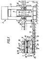
- the rolling stand 2 to be operated by means of the transport vehicle 1 has, as main components, a multi-part stand 3, in which two work rolls 4, 5, supported by support rolls 6 and 7, can be removed in a known manner.
- the two work rolls are set in rotation on the right side of the stand 3 via cardan shafts 8 and 9, which in turn are connected to a drive unit, not shown.
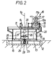
- the transport vehicle 1 in the parking position for changing the work rolls with a box-shaped chassis 10 and a slide 11 which can be moved transversely to the longitudinal axis of the vehicle is supported on a roadway which essentially consists of two steel plates 13 held in a foundation 12 (cf. Fig. 2).
- the carriage 11 is equipped on its upper side with two trough-shaped receptacles 14 and 15 which lie parallel to one another parallel to the longitudinal axis of the vehicle (ie parallel to the axes 4a and 5a of the work rolls in the roll stand 2) and in which one pair of work rolls is supported in a longitudinally displaceable manner can.
- the vertical center plane 1a of the transport vehicle 1 indicated in FIG. 2 coincides with the vertical plane through the axes 4a and 5a. While the receptacle 15 lying outside the central plane 1a carries an exchange unit 16 with new work rolls 17, 18, the receptacle 14 is empty; it can therefore accommodate the work rolls 4 and 5 to be removed.
- the air cushion elements 19 and 20 are connected via lines 25 and 26 to a control unit 27 which, in turn, is connected to a compressed air source 30 via an automatic winding drum 28 also held in the chassis 10 and a supply line 29.
- the control unit will ensure be in the uniform support guaranteeing manner supplied with compressed air that the individual L uftkissenemia.
- the supply line 29 is led outwards through an opening on the underside of the vehicle in such a way that it is deposited below the guide pins 23 in the guide trough 24.
- the transport vehicle 1 In the change position (indicated by dash-dotted lines in FIG. 1), the transport vehicle 1 is supported on an adjustable stop 32, which is fastened on the left side of the roll stand 2, via a bracket 31 fastened to its chassis.
- the stand 3 is at the height of the slide. 11 equipped with an adapted guide track 33, which enables the removal of the pair of work rolls 4, 5 to be removed and then the introduction of the new pair of work rolls 17, 18.
- the carriage 11 In the removal position, the carriage 11 is arranged with respect to the chassis 10 according to FIG. the central plane of the empty receptacle 14 coincides with the central plane 1a.
- the air cushion elements 20 are put into operation by supplying compressed air: the slide 11, which is loaded with two pairs of work rolls at this time, can consequently be moved to the left with little effort to the extent that the axes 17a, 18a defined vertical center plane of the new pair of work rolls coincides with the center plane 1a.
- the air cushion elements 20 are put out of operation before the roller changing process is completed by inserting the new pair of work rolls into the stand 3. Subsequently, the transport vehicle 1 - which only carries the removed work rolls 4, 5 - can be moved to the left into the aforementioned parking position after the air cushion elements 19 have been put into operation.
- the travel of the transport vehicle 1 (which can be extended if necessary) between the parking position and the changing position is slightly more than 3 m; the carriage 11 can travel a total of a displacement which is in the order of three times the width of a work roll set.
- the transport vehicle can of course not only be used when changing the work rolls of the four-roll stand mentioned; in a corresponding manner, it also enables the installation or replacement of the rolls of differently designed roll stands, in particular the rolls of a two-roll stand or the work rolls and / or intermediate rolls of a multi-roll stand.
- the advantage achieved with the subject matter of the invention is in particular that the support of both the transport vehicle itself and the associated carriage has no moving parts and that the transport vehicle, like the carriage, can be moved into the desired position with little effort, even by hand.
Landscapes
- Engineering & Computer Science (AREA)
- Mechanical Engineering (AREA)
- Automobile Manufacture Line, Endless Track Vehicle, Trailer (AREA)
- Rollers For Roller Conveyors For Transfer (AREA)
- Handcart (AREA)
Applications Claiming Priority (2)
| Application Number | Priority Date | Filing Date | Title |
|---|---|---|---|
| DE19853510842 DE3510842A1 (de) | 1985-03-26 | 1985-03-26 | Transportfahrzeug fuer den wechsel insbesondere der arbeitswalzen oder zwischenwalzen von walzgeruesten |
| DE3510842 | 1985-03-26 |
Publications (2)
| Publication Number | Publication Date |
|---|---|
| EP0195953A2 true EP0195953A2 (fr) | 1986-10-01 |
| EP0195953A3 EP0195953A3 (fr) | 1988-09-14 |
Family
ID=6266312
Family Applications (1)
| Application Number | Title | Priority Date | Filing Date |
|---|---|---|---|
| EP86102708A Withdrawn EP0195953A3 (fr) | 1985-03-26 | 1986-03-01 | Véhicule de transport pour le changement, notamment des cylindres de travail ou des cylindres intermédiaires de cages de laminage |
Country Status (2)
| Country | Link |
|---|---|
| EP (1) | EP0195953A3 (fr) |
| DE (1) | DE3510842A1 (fr) |
Cited By (3)
| Publication number | Priority date | Publication date | Assignee | Title |
|---|---|---|---|---|
| EP0684089A3 (fr) * | 1994-05-23 | 1996-03-20 | Davy Mckee Poole | Dispositif pour changer les cylindres d'un laminoir à plusieurs cylindres. |
| CN116441318A (zh) * | 2023-04-12 | 2023-07-18 | 一重集团大连工程技术有限公司 | 一种轧机换辊装置 |
| CN119608778A (zh) * | 2025-01-02 | 2025-03-14 | 一重集团大连工程技术有限公司 | 一种下传动立辊轧机接轴更换装置 |
Families Citing this family (1)
| Publication number | Priority date | Publication date | Assignee | Title |
|---|---|---|---|---|
| CN117161973A (zh) * | 2023-10-17 | 2023-12-05 | 瑨祥(南通)机电设备有限公司 | 一种光整机工作辊快速换辊结构 |
Family Cites Families (5)
| Publication number | Priority date | Publication date | Assignee | Title |
|---|---|---|---|---|
| DE1189861B (de) * | 1962-08-04 | 1965-03-25 | Westland Aircraft Ltd | Palette zum Tragen und Transportieren von Lasten |
| GB1281763A (en) * | 1968-07-19 | 1972-07-12 | Masch Und Werkzzeugbau Gmbh | Improvements in or relating to rolling mill stands |
| US3842639A (en) * | 1973-06-20 | 1974-10-22 | Mesta Machine Co | Side-shifting mill roll |
| SU599866A1 (ru) * | 1976-01-04 | 1978-04-19 | Днепропетровский Ордена Трудового Красного Знамени Металлургический Институт | Устройство дл боковой фиксации подушек прокатки валков |
| DE2721436A1 (de) * | 1977-05-12 | 1978-11-16 | Schloemann Siemag Ag | Arbeitswalzen-schnellwechselvorrichtung fuer walzgerueste |
-
1985
- 1985-03-26 DE DE19853510842 patent/DE3510842A1/de not_active Withdrawn
-
1986
- 1986-03-01 EP EP86102708A patent/EP0195953A3/fr not_active Withdrawn
Cited By (3)
| Publication number | Priority date | Publication date | Assignee | Title |
|---|---|---|---|---|
| EP0684089A3 (fr) * | 1994-05-23 | 1996-03-20 | Davy Mckee Poole | Dispositif pour changer les cylindres d'un laminoir à plusieurs cylindres. |
| CN116441318A (zh) * | 2023-04-12 | 2023-07-18 | 一重集团大连工程技术有限公司 | 一种轧机换辊装置 |
| CN119608778A (zh) * | 2025-01-02 | 2025-03-14 | 一重集团大连工程技术有限公司 | 一种下传动立辊轧机接轴更换装置 |
Also Published As
| Publication number | Publication date |
|---|---|
| EP0195953A3 (fr) | 1988-09-14 |
| DE3510842A1 (de) | 1986-10-09 |
Similar Documents
| Publication | Publication Date | Title |
|---|---|---|
| DE2840773C2 (de) | Halte- und Führungskorb für den Dorn eines Walzwerks | |
| DE2047480A1 (de) | Raupenkran mit veränderbarer Spurweite | |
| AT392305B (de) | Vorrichtung zum auswechseln elastischer-walzen eines superkalanders | |
| DE1283782B (de) | Universalwalzgeruest mit die Staenderfenster ueberbrueckenden Buegeln | |
| DE2840919B2 (de) | An einer Streckenvortriebsmaschine angeordnete Vorrichtung zum Einbringen von Ausbaurahmen eines provisorischen Streckenausbaus | |
| DE69101995T2 (de) | Anlage zum Richten. | |
| EP0112981A2 (fr) | Dispositif de changement de cylindres pour cages de laminoir à 6 cylindres | |
| DE3541906C1 (de) | Wickelmaschine zum Aufwickeln einer Iaengsgeteilten Bahn | |
| EP0569719A1 (fr) | Système de transport de bande | |
| EP0195953A2 (fr) | Véhicule de transport pour le changement, notamment des cylindres de travail ou des cylindres intermédiaires de cages de laminage | |
| DE60119745T2 (de) | Anlage und verfahren zur behandlung einer formmaterialbahn | |
| EP0050362A2 (fr) | Dispositif de nettoyage de faisceaux de tubes | |
| DE3144927C2 (fr) | ||
| EP0853143A1 (fr) | Dispositif pour déplacer des traverses utilisées dans le transport d'objets | |
| DE3420829A1 (de) | System zum auswechseln von walzgeruesten eines formstahl-walzwerks, als walzgeruesttraeger dienender mehrfachfunktions-laufwagen fuer das aufstellen an den walzplaetzen und den transport zu den vormontagestellen | |
| DE551075C (de) | Vorrichtung zum Einlagern von Papierrollen in ihre Haltedorne bei Rotationsdruckmaschinen | |
| DE1031726B (de) | Vorrichtung fuer Fahrzeuge, insbesondere Kraftfahrzeuge zum Tragen eines fahrbaren Behaelters auf der Ladeflaeche | |
| DE3237904A1 (de) | Vorrichtung zum austausch von walzen in einem rohrwalzwerk | |
| DE2314077B2 (de) | Vorrichtung zum Transportieren von Rohren durch eine Wärmebehandlungseinrichtung | |
| DE3842132C1 (en) | Roller table in a band accumulator | |
| DE2905615C2 (de) | Sinterbrecher | |
| DE2929423A1 (de) | Einrichtung zum walzenwechsel der horizontal- und vertikalwalzensaetze bei universalwalzgeruesten | |
| DE3340737A1 (de) | Gleisbaumaschine zum greifen und tragen von montierten gleisabschnitten und/oder gleisverbindungen | |
| DE2837317C2 (de) | Entladevorrichtung an einem landwirtschaftlichen Lade- bzw. Transportwagen | |
| DE2905948A1 (de) | Profiliermaschine |
Legal Events
| Date | Code | Title | Description |
|---|---|---|---|
| PUAI | Public reference made under article 153(3) epc to a published international application that has entered the european phase |
Free format text: ORIGINAL CODE: 0009012 |
|
| AK | Designated contracting states |
Kind code of ref document: A2 Designated state(s): FR GB IT |
|
| PUAL | Search report despatched |
Free format text: ORIGINAL CODE: 0009013 |
|
| AK | Designated contracting states |
Kind code of ref document: A3 Designated state(s): FR GB IT |
|
| STAA | Information on the status of an ep patent application or granted ep patent |
Free format text: STATUS: THE APPLICATION IS DEEMED TO BE WITHDRAWN |
|
| 18D | Application deemed to be withdrawn |
Effective date: 19890315 |
|
| RIN1 | Information on inventor provided before grant (corrected) |
Inventor name: WEITERMANN, HANS-DIETER |