EP0196003A2 - Articulation de pivotement d'une pipe de transport pneumatique par un cantilever - Google Patents
Articulation de pivotement d'une pipe de transport pneumatique par un cantilever Download PDFInfo
- Publication number
- EP0196003A2 EP0196003A2 EP86103680A EP86103680A EP0196003A2 EP 0196003 A2 EP0196003 A2 EP 0196003A2 EP 86103680 A EP86103680 A EP 86103680A EP 86103680 A EP86103680 A EP 86103680A EP 0196003 A2 EP0196003 A2 EP 0196003A2
- Authority
- EP
- European Patent Office
- Prior art keywords
- sealing sheet
- rotary cylinder
- sealing
- strip
- swivel
- Prior art date
- Legal status (The legal status is an assumption and is not a legal conclusion. Google has not performed a legal analysis and makes no representation as to the accuracy of the status listed.)
- Granted
Links
Images

Classifications
-
- B—PERFORMING OPERATIONS; TRANSPORTING
- B65—CONVEYING; PACKING; STORING; HANDLING THIN OR FILAMENTARY MATERIAL
- B65G—TRANSPORT OR STORAGE DEVICES, e.g. CONVEYORS FOR LOADING OR TIPPING, SHOP CONVEYOR SYSTEMS OR PNEUMATIC TUBE CONVEYORS
- B65G53/00—Conveying materials in bulk through troughs, pipes or tubes by floating the materials or by flow of gas, liquid or foam
- B65G53/34—Details
- B65G53/52—Adaptations of pipes or tubes
-
- F—MECHANICAL ENGINEERING; LIGHTING; HEATING; WEAPONS; BLASTING
- F16—ENGINEERING ELEMENTS AND UNITS; GENERAL MEASURES FOR PRODUCING AND MAINTAINING EFFECTIVE FUNCTIONING OF MACHINES OR INSTALLATIONS; THERMAL INSULATION IN GENERAL
- F16L—PIPES; JOINTS OR FITTINGS FOR PIPES; SUPPORTS FOR PIPES, CABLES OR PROTECTIVE TUBING; MEANS FOR THERMAL INSULATION IN GENERAL
- F16L41/00—Branching pipes; Joining pipes to walls
Definitions
- the invention relates to a swivel joint for a pneumatic conveying line which can be pivoted with a boom, in particular for the swivel joint of suction lifter booms, with two joint parts which are attached to one another, of which one joint part is designed as a bearing body and is fastened to a recipient and the other joint part is designed as a rotating cylinder , which receives the delivery line opening into the recipient, transversely axially and, together with it, is rotatable relative to the first joint part, and with a seal for sealing both joint parts from the atmosphere.
- Such swivel joints are indispensable in all delivery lines arranged on a movable boom, in order to be able to transfer the conveying air and the goods transported by it from the movable part of the conveying device through the pivot point or hinge point to its stationary part and thereby the necessary for the conveyance Maintain negative pressure.
- a pipe boom for suction conveyor systems is known in which between the pipe boom on the one hand and the recipient on the other hand a swivel joint consisting of a bend rotatable about a vertical axis and a swivel joint mounted above it about a horizontal axis is provided, whereby the elbow in a semi-cylindrical joint socket receives the chick in a pivotable manner and the latter has a transverse axial passage channel, which has one end in the elbow and its the other end opens into the pipe of the pipe boom firmly connected to it.
- Both known swivel joints have not been particularly satisfactory in practical operation; they are complicated in construction and require a fine machining of the joint parts, which makes them expensive, which is further increased by the fact that - so that the rotary cylinder axis and the boom pivot axis are aligned - the boom and the rotary cylinder have to be drilled together on one boring machine.
- the first-mentioned swivel seals only through the more or less exact fit, that is, it is a mere gap seal that constantly has corresponding leakage losses and is not rainproof.
- the second-mentioned swivel joint from the prior art has additional elastic sealing strips, but these are relatively inelastic because of their short, freely movable length in the transverse direction and therefore require precise mechanical machining of the rotating cylinder; in addition, an axial sealing of the rotary cylinder is necessary here, which requires further seals and mechanically machined sliding surfaces on both end faces as well as precise axial guidance of the rotary cylinder; due to the minimal thickness of the sealing strips of 1 - 2 mm, they fold in and lift off the rotary cylinder, rain and dirt get under the sealing lip and into the recipient and further into the cellular wheel sluice, so that the latter will rust on its sealing surfaces and eventually block .
- the invention has for its object to improve a hinge of the type cited in such a way that it is easier to produce with sufficient mobility and without exact fits and drilling with the boom and its joint parts reliably both vacuum-tight and rain and dust-tight from a seal are covered, which in turn should be permanent and maintenance-free, easy to assemble and retightenable with optimum mobility or conformability.
- the design of the sealing sheet according to claim 2 is because of the resulting long sealing tabs, the free length of which is eight to ten times the sheet thickness, particularly inexpensive to seal and simple to manufacture.
- the design according to claim 3 makes it possible to pull the sealing sheet smooth in the corner parts in order to avoid folds and to easily retighten them if necessary.
- the claim 4 gives materials for the sealing sheet that fit particularly well on the rotary cylinder, with silicone being preferred to be suitable for low temperatures and resistant to strong solar radiation.
- the claim 5 teaches a material and labor favorable design of the bearing body for the rotary cylinder with ideal receiving surfaces for the sealing sheet and the clamping means for fixing the latter.
- the claims 6 and 7 outline advantageous options for biasing the sealing edges of the sealing sheet.
- the patent claim 8 teaches a type of attachment for the terminal strips, which is simple and reliable and allows a quick replacement of the sealing sheet if necessary.
- the design for the rotary cylinder specified in claim 9 is simple to manufacture, like the bearing body, and - because its guide tube loosely receives the delivery line - requires no precise mounting in it, i.e. the rotary cylinder can rotate relative to the boom pivot axis within wide tolerances the axis is therefore unnecessary.
- the proposal according to claim 10 saves surface processing and ensures that the rotary cylinder remains rust-free in places on its jacket that are exposed to the weather or its surface quality remains unchanged.
- the further training according to claim 11 finally ensures that false air, rain water and snow and dust cannot penetrate into the recipient and the downstream rotary valve even through the gap between the guide tube and delivery line.
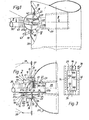
- the swivel joint is essentially made up of two joint parts mounted on one another, namely a bearing body 1 and a rotating cylinder 2, which are sealed from the atmosphere by a seal in the form of a sealing sheet 3 made of silicone and comprising four sealing tabs 3a to 3d.
- the bearing body 1 is composed of a flange frame 4 with two horizontal limbs 5, 6 and two vertical limbs 7, 8 and two approximately semicircular side cheeks 9, 10, which are at a distance corresponding to the length of the rotary cylinder 2 are arranged on one side of the flange frame 4 and welded to it.
- Two webs 11, 12 directly abutting the flange frame 4 connect the two side cheeks at the top and bottom (FIGS. 1, 4).
- Each of these two webs 11, 12 is arranged with a certain inclination to the longitudinal center plane of the flange frame 4 and thus predetermines this inclination for the associated sealing tab 3a or 3b of the sealing sheet 3.
- the side walls 9, 10 each have at their semicircular edge an axially outwardly facing flange 13 or 14 and near the flange frame 4 a bearing bore 15 or 16 and are stiffened by two externally welded ribs 17.
- the bearing body 1 is fastened to a mounting plate 19 by means of screws 18, which are inserted through holes drilled all around in its flange frame 4 (FIG. 4).
- the mounting plate 19 is welded to the recipient 20 of the suction lifter to form a unit and has a recess 21 for the passage of the rotary cylinder 2, guide tube and delivery line into the interior of the recipient 20 (FIGS. 1, 2).
- the outer surfaces of the two horizontal legs 5, 6 of the flange frame 4 and the outer surfaces of the two semicircular flanges 13, 14 of the side walls 9, 10 form four strip-shaped receiving surfaces that embody a kind of spatial surface frame of the bearing body 1 for receiving the sealing sheet 3.
- the rotary cylinder 2 is designed as a hollow cylinder made of stainless steel sheet and surrounded by a jacket 22 and two end walls 23, 24, which has a central bearing bore 25 or 26 in each end wall 23 or 24.
- a guide tube 27 penetrates its jacket 22 in such a way that its longitudinal axes intersect (FIGS. 1, 2).
- the guide tube 27 welded to the rotary cylinder 2 projects with its short stub 27a outwards in the direction of the boom 28 of the suction lifter and with its long stump 27b into the recipient 20 and at the end of this stump 27b carries a baffle head 29 so that it can pivot relative to it.
- the guide tube 27 slidably receives the pneumatic conveying line 30 which runs along the arm 28 and which is close to the End of the stump 27b leads (Fig.2).
- a sealing sleeve 41 closes the gap between the delivery line 30 and the guide tube 27.
- the rotary cylinder 2 is rotatably supported by its bearing bores 25, 26 on two thru axles 31, 32, of which the thru axle 31 is received by the bearing bore 15 of the side wall 9 and the coaxial bearing bore in a rib 33 welded to the recipient 20 and by an axle holder 35 is secured and the thru-axle 32 is received by the bearing bore 16 of the side wall 10 and the same-axis bearing bore in a rib 34 which is also welded to the recipient 20 and is secured by means of an axle holder 36 (FIG. 2).
- the two thru axles 31, 32 are aligned with the pivot axis 37 of the arm 28, so that when the arm 28 together with the conveying line 30 is pivoted, the guide tube 27 and the rotary cylinder 2 carry out this
- the sealing sheet 3 ' made of silicone is rectangular in shape and 8 mm thick and has two rows at the top and bottom near its edge and two rows of fastening holes 38 on the left and right, which are shaped as elongated holes parallel to the sealing sheet.
- the sealing sheet 3 has an axially symmetrical, rectangular recess 39, on the edge 40 of which the sealing sheet 3 is sharpened (FIG. 3).
- the edge 40 of the recess 39 is identical to the four inner sides 40a, 40b, 40c and 40d of the sealing sheet 3, which represent its sealing edges.
- the length of the recess 39 corresponds to the pivoting angle of the guide tube 27 or the arm 28 dimensioned.
- clamping means in the form of straight and curved clamping strips which are fixed by means of screws, are used, namely at the top the straight terminal strip 42 with screws 48 and the additional terminal strip 44 with screws 49 and below the straight terminal strip 43 with screws 48 and the additional terminal strip 45 with screws 49 and further on the left the curved terminal strip 46 and on the right side the curved terminal strip 47, both with screws 50.
- the terminal strips 42 to 47 have through holes 53, 54 and 55 arranged at a suitable distance from one another.
- a lining strip 51 with a wedge-shaped cross section is located on the receiving surface of each flange 13 or 14 facing the sealing sheet 3 and on the side of the sealing sheet 3 facing the curved clamping strip 46 or 47 associated with this flange 13 or 14, a cross-sectionally wedge-shaped lining strip 52 is attached, the thickness of the lining strips 51 decreasing towards the rotating cylinder 2 and the thickness of the lining strips 52 towards the rotating cylinder 2 increases (Fig. 4, 6).
- FIGS. 5 and 6 show in a straight area of the sealing sheet 3 (FIG. 5) and in a curved area of the sealing sheet 3 (FIG. 6) through the webs 11 and 12 on the one hand and the lining strips 51, 52 on the other hand predetermined direction of a straight or curved sealing tab 3b or the sealing sheet 3 in dash-dotted lines Lines and their deflection forced by the rotary cylinder 2 (see the angles alpha and beta in FIGS. 5 and 6), which effects the desired prestressing of the said sealing edges 40a to 40.d.
- the cutting edge-shaped sealing edge 40a or 40b of a straight sealing tab 3a or 3b of the sealing sheet 3 peels off by acting as a scraper or wiper, water or snow as well as dirt etc. from its jacket 22 when the rotary cylinder 2 moves.
- the progress achieved with the invention consists of a simple, inexpensive swivel joint that can be manufactured inexpensively without precise fits, the surface to be sealed can remain unprocessed and the one-piece, leaf-shaped seal has a multiple of the sealing leaf thickness, long and thick and therefore kink-resistant sealing tabs, sufficient tightness and long service life guaranteed, a large freedom of movement of the joint parts allows and - because it is easily accessible - can be replaced and re-tensioned in the shortest possible time additional advantages are the insensitivity of the sealing sheet to the drawing in of foreign bodies, ice drops and crust, the visibility of the sealing function, the security against freezing and the possibility of removing foreign bodies by simply folding up the sealing tab in question.
Landscapes
- Engineering & Computer Science (AREA)
- General Engineering & Computer Science (AREA)
- Mechanical Engineering (AREA)
- Joints Allowing Movement (AREA)
- Air Transport Of Granular Materials (AREA)
- Quick-Acting Or Multi-Walled Pipe Joints (AREA)
Priority Applications (1)
| Application Number | Priority Date | Filing Date | Title |
|---|---|---|---|
| AT86103680T ATE37522T1 (de) | 1985-03-23 | 1986-03-18 | Drehgelenk fuer eine pneumatische, mit einem ausleger schwenkbewegliche foerderleitung. |
Applications Claiming Priority (2)
| Application Number | Priority Date | Filing Date | Title |
|---|---|---|---|
| DE19853510702 DE3510702A1 (de) | 1985-03-23 | 1985-03-23 | Drehgelenk fuer eine pneumatische, mit einem ausleger schwenkbewegliche foerderleitung |
| DE3510702 | 1985-03-23 |
Publications (3)
| Publication Number | Publication Date |
|---|---|
| EP0196003A2 true EP0196003A2 (fr) | 1986-10-01 |
| EP0196003A3 EP0196003A3 (en) | 1987-07-01 |
| EP0196003B1 EP0196003B1 (fr) | 1988-09-28 |
Family
ID=6266216
Family Applications (1)
| Application Number | Title | Priority Date | Filing Date |
|---|---|---|---|
| EP86103680A Expired EP0196003B1 (fr) | 1985-03-23 | 1986-03-18 | Articulation de pivotement d'une pipe de transport pneumatique par un cantilever |
Country Status (4)
| Country | Link |
|---|---|
| EP (1) | EP0196003B1 (fr) |
| JP (1) | JPS61263521A (fr) |
| AT (1) | ATE37522T1 (fr) |
| DE (2) | DE3510702A1 (fr) |
Cited By (1)
| Publication number | Priority date | Publication date | Assignee | Title |
|---|---|---|---|---|
| CN101694223B (zh) * | 2009-10-12 | 2012-05-23 | 顾飞龙 | 空气泄压开关 |
Family Cites Families (4)
| Publication number | Priority date | Publication date | Assignee | Title |
|---|---|---|---|---|
| DE948318C (de) * | 1954-03-13 | 1956-08-30 | Miag Muehlenbau & Ind Gmbh | Saugfoerderanlage zum Entladen von koernigem Schuettgut |
| NL6810185A (fr) * | 1968-07-18 | 1970-01-20 | ||
| DE2526530A1 (de) * | 1975-06-13 | 1976-12-16 | Martin Westenberg | Vorrichtung zum absaugen von staubfoermigem, koernigem oder rieselfaehigem gut aus schiffen |
| DE3217398C2 (de) * | 1982-05-08 | 1987-03-12 | Société Anonyme Vigan N.V., Nivelles | Saugluft-Förderanlage für den pneumatischen Transport von Schüttgut |
-
1985
- 1985-03-23 DE DE19853510702 patent/DE3510702A1/de not_active Withdrawn
-
1986
- 1986-03-18 AT AT86103680T patent/ATE37522T1/de not_active IP Right Cessation
- 1986-03-18 DE DE8686103680T patent/DE3660800D1/de not_active Expired
- 1986-03-18 EP EP86103680A patent/EP0196003B1/fr not_active Expired
- 1986-03-22 JP JP61062023A patent/JPS61263521A/ja active Granted
Cited By (1)
| Publication number | Priority date | Publication date | Assignee | Title |
|---|---|---|---|---|
| CN101694223B (zh) * | 2009-10-12 | 2012-05-23 | 顾飞龙 | 空气泄压开关 |
Also Published As
| Publication number | Publication date |
|---|---|
| JPS61263521A (ja) | 1986-11-21 |
| EP0196003A3 (en) | 1987-07-01 |
| ATE37522T1 (de) | 1988-10-15 |
| DE3510702A1 (de) | 1986-09-25 |
| DE3660800D1 (en) | 1988-11-03 |
| JPH048336B2 (fr) | 1992-02-14 |
| EP0196003B1 (fr) | 1988-09-28 |
Similar Documents
| Publication | Publication Date | Title |
|---|---|---|
| DE1482762A1 (de) | Trommelwender | |
| DE3817349C2 (fr) | ||
| DE2364904B1 (de) | Absperrorgan für eine schleißendes Gut führende Leitung | |
| DE3722911C1 (de) | Anlage zum pneumatischen Foerdern von Schuettguetern | |
| DE4019962A1 (de) | Loetmaschine, die mit schutzgas arbeitet und mit automatisch betriebenen schleusentueren versehen ist | |
| DE3235227C2 (de) | Reinigungsvorrichtung für Gebäudefassaden | |
| EP0196003B1 (fr) | Articulation de pivotement d'une pipe de transport pneumatique par un cantilever | |
| DE2262775C3 (de) | Gelenkige Rohrverbindung | |
| EP0229087A1 (fr) | Tuyauterie souple | |
| DE19837325C1 (de) | Schwenkschieber zum Absperren einer Einfüllöffnung in Druckgefäßen | |
| DE3423870C2 (de) | Spannvorrichtung für pneumatische Förderanlagen | |
| DE3202076A1 (de) | Roboter-arm | |
| CH616367A5 (en) | Turning bar with air circulation | |
| CH686733A5 (de) | Vorrichtung zum Auftragen von Moertel. | |
| DE2146314C3 (de) | Scharnier für einliegende Türen | |
| DE60303347T2 (de) | Schnellkupplung mit Kniehebelbetätigung | |
| DE3523647A1 (de) | Anlage zur reinigung von werkstueck-oberflaechen mit strahlmitteln | |
| DE2303777A1 (de) | Weiche zur wahlweisen verbindung mehrerer rohre oder schlaeuche | |
| EP3406953B1 (fr) | Traversée murale pour deux conduites | |
| DE19837306C1 (de) | Reinigungsvorrichtung | |
| DE2146314B2 (de) | Scharnier fuer einliegende tueren | |
| DE2909256A1 (de) | Steuervorrichtung einer mehrzylinderpumpe fuer breiige massen | |
| DE2850222A1 (de) | Drosselklappenventil | |
| DE102022121226A1 (de) | Materialaufnahmegerät für einen Saugbagger sowie Saugbagger mit diesem Materialaufnahmegerät | |
| DE1814589B1 (de) | Schwenkrohrweiche fuer pneumatische Foerderanlagen |
Legal Events
| Date | Code | Title | Description |
|---|---|---|---|
| PUAI | Public reference made under article 153(3) epc to a published international application that has entered the european phase |
Free format text: ORIGINAL CODE: 0009012 |
|
| AK | Designated contracting states |
Kind code of ref document: A2 Designated state(s): AT BE CH DE FR GB IT LI NL SE |
|
| PUAL | Search report despatched |
Free format text: ORIGINAL CODE: 0009013 |
|
| RHK1 | Main classification (correction) |
Ipc: B65G 53/54 |
|
| AK | Designated contracting states |
Kind code of ref document: A3 Designated state(s): AT BE CH DE FR GB IT LI NL SE |
|
| 17P | Request for examination filed |
Effective date: 19870827 |
|
| 17Q | First examination report despatched |
Effective date: 19880315 |
|
| GRAA | (expected) grant |
Free format text: ORIGINAL CODE: 0009210 |
|
| AK | Designated contracting states |
Kind code of ref document: B1 Designated state(s): AT BE CH DE FR GB IT LI NL SE |
|
| REF | Corresponds to: |
Ref document number: 37522 Country of ref document: AT Date of ref document: 19881015 Kind code of ref document: T |
|
| REF | Corresponds to: |
Ref document number: 3660800 Country of ref document: DE Date of ref document: 19881103 |
|
| ET | Fr: translation filed | ||
| GBT | Gb: translation of ep patent filed (gb section 77(6)(a)/1977) | ||
| ITF | It: translation for a ep patent filed | ||
| PLBE | No opposition filed within time limit |
Free format text: ORIGINAL CODE: 0009261 |
|
| STAA | Information on the status of an ep patent application or granted ep patent |
Free format text: STATUS: NO OPPOSITION FILED WITHIN TIME LIMIT |
|
| 26N | No opposition filed | ||
| ITTA | It: last paid annual fee | ||
| PGFP | Annual fee paid to national office [announced via postgrant information from national office to epo] |
Ref country code: CH Payment date: 19920131 Year of fee payment: 7 |
|
| PGFP | Annual fee paid to national office [announced via postgrant information from national office to epo] |
Ref country code: SE Payment date: 19920220 Year of fee payment: 7 |
|
| PGFP | Annual fee paid to national office [announced via postgrant information from national office to epo] |
Ref country code: FR Payment date: 19920221 Year of fee payment: 7 |
|
| PGFP | Annual fee paid to national office [announced via postgrant information from national office to epo] |
Ref country code: AT Payment date: 19920310 Year of fee payment: 7 |
|
| PGFP | Annual fee paid to national office [announced via postgrant information from national office to epo] |
Ref country code: GB Payment date: 19920311 Year of fee payment: 7 |
|
| PGFP | Annual fee paid to national office [announced via postgrant information from national office to epo] |
Ref country code: BE Payment date: 19920312 Year of fee payment: 7 |
|
| PGFP | Annual fee paid to national office [announced via postgrant information from national office to epo] |
Ref country code: DE Payment date: 19920321 Year of fee payment: 7 |
|
| PGFP | Annual fee paid to national office [announced via postgrant information from national office to epo] |
Ref country code: NL Payment date: 19920331 Year of fee payment: 7 |
|
| PG25 | Lapsed in a contracting state [announced via postgrant information from national office to epo] |
Ref country code: GB Effective date: 19930318 Ref country code: AT Effective date: 19930318 |
|
| PG25 | Lapsed in a contracting state [announced via postgrant information from national office to epo] |
Ref country code: SE Effective date: 19930319 |
|
| PG25 | Lapsed in a contracting state [announced via postgrant information from national office to epo] |
Ref country code: LI Effective date: 19930331 Ref country code: CH Effective date: 19930331 Ref country code: BE Effective date: 19930331 |
|
| BERE | Be: lapsed |
Owner name: BUHLER-MIAG G.M.B.H. Effective date: 19930331 |
|
| PG25 | Lapsed in a contracting state [announced via postgrant information from national office to epo] |
Ref country code: NL Effective date: 19931001 |
|
| NLV4 | Nl: lapsed or anulled due to non-payment of the annual fee | ||
| GBPC | Gb: european patent ceased through non-payment of renewal fee |
Effective date: 19930318 |
|
| PG25 | Lapsed in a contracting state [announced via postgrant information from national office to epo] |
Ref country code: FR Effective date: 19931130 |
|
| REG | Reference to a national code |
Ref country code: CH Ref legal event code: PL |
|
| PG25 | Lapsed in a contracting state [announced via postgrant information from national office to epo] |
Ref country code: DE Effective date: 19931201 |
|
| REG | Reference to a national code |
Ref country code: FR Ref legal event code: ST |
|
| EUG | Se: european patent has lapsed |
Ref document number: 86103680.4 Effective date: 19931008 |
|
| PG25 | Lapsed in a contracting state [announced via postgrant information from national office to epo] |
Ref country code: IT Free format text: LAPSE BECAUSE OF NON-PAYMENT OF DUE FEES Effective date: 20050318 |