EP0196105A2 - Verfahren und Anordnung zum Fördern von Schüttgut - Google Patents
Verfahren und Anordnung zum Fördern von Schüttgut Download PDFInfo
- Publication number
- EP0196105A2 EP0196105A2 EP86104271A EP86104271A EP0196105A2 EP 0196105 A2 EP0196105 A2 EP 0196105A2 EP 86104271 A EP86104271 A EP 86104271A EP 86104271 A EP86104271 A EP 86104271A EP 0196105 A2 EP0196105 A2 EP 0196105A2
- Authority
- EP
- European Patent Office
- Prior art keywords
- outlet
- hopper
- gate
- elongated
- particulate material
- Prior art date
- Legal status (The legal status is an assumption and is not a legal conclusion. Google has not performed a legal analysis and makes no representation as to the accuracy of the status listed.)
- Withdrawn
Links
Images



Classifications
-
- B—PERFORMING OPERATIONS; TRANSPORTING
- B65—CONVEYING; PACKING; STORING; HANDLING THIN OR FILAMENTARY MATERIAL
- B65D—CONTAINERS FOR STORAGE OR TRANSPORT OF ARTICLES OR MATERIALS, e.g. BAGS, BARRELS, BOTTLES, BOXES, CANS, CARTONS, CRATES, DRUMS, JARS, TANKS, HOPPERS, FORWARDING CONTAINERS; ACCESSORIES, CLOSURES, OR FITTINGS THEREFOR; PACKAGING ELEMENTS; PACKAGES
- B65D88/00—Large containers
- B65D88/54—Large containers characterised by means facilitating filling or emptying
- B65D88/64—Large containers characterised by means facilitating filling or emptying preventing bridge formation
Definitions
- This invention relates to an apparatus and method for unloading from cargo holds or hoppers, cargoes of solid particulate material, especially those referred to in the trade as "sticky".
- Particulate material has characteristics which make it difficult to unload from hoppers because of the arching or bridging phenomenon.
- Self-unloading seagoing and lakegoing vessels which carry particulate materials in bulk are equipped with large elongated hoppers having inwardly and downwardly sloping sides leading to an outlet overlying a conveyor.
- a simplified view of a self-unloading vessel is contained in U.S. Patent 2,815,134, Borrowdale (1957).
- the vessel illustrated is, of course, much smaller than the typical vessels the applicant is talking about and only two side-by-side hopper outlets are shown, but the patent does serve to give a general idea of the type of vessel to which the invention applies and of the unloading problem.
- the present invention is particularly applicable to self-unloading seagoing and lakegoing vessels having a length of 700 to 800 feet and a width of 75 to 100 feet.
- a typical vessel of this type will have a cargo space of some 500 feet long divided fore and aft by bulkheads into, say, five holds each about 100 feet long.
- Two conveyor belts, one at each side of the vessel extend the entire length of the cargo space underneath the holds and beneath the bulkheads separating them.
- each hold has a pair of side-by-side hoppers about 40 feet wide at the top with sides sloping inward at a downward angle of as little as 35° towards an outlet about 41 to 6 feet wide.
- the shallow slope is to avoid losing cubic capacity, that is, to use as much of the hold space as possible for the cargo.
- These hoppers may have a head of 30 or 40 feet of material above a long discharge channel closed by gates which form a floor which opens to allow the escape of material.
- the outlet to the hopper is controlled by gates, for example, swing gates are preferably used, as shown in prior patent application 404,544, Pole, filed August 2, 1982, which disclosure is hereby incorporated by reference.
- the swing gates are adapted to swing between a position in which they close the opening and a position where they swing upward to disturb the material in the bottom of the hopper to facilitate its flow. It may be desirable to have one horizontally sliding gate at the upstream end of the hopper or after each bank of several swing gates.
- the sliding gate does not meet the resistance of the material so that it may be opened independently of the swing gates so as to allow a certain amount of material to flow out and facilitate the entry of the swing gates into the body of the material.
- Each ship has to be fitted to handle a whole range of particulate cargo, running from very fine material or dust up to lumps of 8 to 15 inches in diameter.
- gypsum limestone may contain 10% by weight of lumps of this size.
- the containing and discharging arrangement to which this invention applies includes an elongated hopper for positioning above an elongated conveyor belt extending in a substantially horizontal direction from an upstream end to a downstream end.
- the hopper has a discharge structure including opposed downwardly and inwardly sloping sides, extending towards each other to terminate in elongated parallel margins, defining between them an elongated discharge channel to overlie the conveyor.
- Transverse spaced-apart members extend between the respective margins to divide the discharge channel into a series of discrete outlets in the direction of the belt providing, together, a long narrow outlet.
- Gate means for each discrete outlet forms part of a floor of the hopper, when closed and, when opened, allows a controlled discharge of the material from the outlet as it gravitates from the sloping sides.
- sticky particulate material tends to pack in the hopper forming a natural self-supporting arch over the outlet which causes a no-flow condition.
- the nature of the arch depends on the particular material, its moisture content, particle size, shape and uniformity of the particles, degree of compactability, the presence of lumps of agglomerated material, content of foreign matter, the head of material above, and other factors.
- Identical particulate material behaves exactly in the same way in identical hoppers in terms of forming an arch of identical dimensions because each given material has its own maximum arch span. A decrease or increase in moisture content changes the natural span of the arch.
- the arch for each particulate material has a maximum span, sometimes as much as 12 feet in diameter.
- This gating means has been found effective in breaking up lengthwise or fore and aft arching resulting from the compacting of the particulate material, as described.
- the applicant has found that there is occasionally the problem of material arching in the other direction between the two hopper slopes, that is, athwartships or at right angles to the fore and aft direction of the belt.
- both the fore and aft and athwartships arching must be dealt with.
- the applicant's prior application 404,544 describes the opening of the gates to allow flow of material through the outlet of the hopper and the simultaneous disturbing of the material above the outlet to break up the fore and aft arch formations. Breaking up athwartships arches, in accordance with a preferred aspect of the invention, is done as follows.
- the natural flow of particulate contents of the hopper is divided into a central stream of somewhat the width of the outlet, centrally of the hopper, by dividing a central space along its length in the up and down direction. This may be done with parallel spaced-apart elongated walls or baffles cutting across the normal arc of arch formation and providing a central channel and flanking channels each having an entrance centrally of the mass of material in the hopper and an outlet into a common channel spaced above the outlet of the hopper.
- this structure may take the form of baffles, each having a laterally extending flange or pressure shield at or near their top margins.
- each particulate material has the phenomenon of forming an arch of consolidated material of particular width depending on the material.
- the present invention and the previous invention (relating to breaking up the fore and aft arching), aim to provide an opening which is effectively at least 20 feet long so as to be greater than any arch which might be formed by the material.
- the invention also contemplates the combination, with the arrangement of swing gates as disclosed in prior U.S. patent application 404,544, the disclosure of which is hereby incorporated by reference.
- the central baffles or walls are preferably mounted to the sidewalls of the hopper by supports spaced periodically along the length of the hopper. Athwartship supports extend between the lower part of the baffles or walls at intervals to mount the swing gates.
- the invention also contemplates a method of storing cargo of finely divided flowable material in an elongated hopper having opposed sides sloping inwardly and downwardly towards a long narrow gated outlet overlying a conveyor running lengthwise of the hopper, and subsequently discharging the material from the hopper.
- This method involves charging the hopper with the gates closed, with a mass of particulate material, while separating the material, at an intermediate zone within the mass and spaced above the outlet, along the length of the hopper, into several vertical piles merging above and below the partitioning and shielding segments of the material above the gates from compaction forces.
- the gates are opened to allow the material to escape. Essentially, the material in the funnel immediately above the outlet falls through it.
- the material from the respective piles flows into the void left by the initial flow and arching is prevented since the material is divided across the normal lines of arch formation.
- the material is also baffled in the horizontal direction across part of at least one of the piles to reduce pressure on the material in it and prevent packing.
- Figs. 1, 2 and 3 illustrate a shipboard hopper whose outlet is equipped with a cooperating plurality of swing gates according to U.S. patent application 404,544.
- the gates swing, in the longitudinal direction of the hopper outlet, between closed position and open position within the hopper above the outlet. This arrangement is effective for breaking up the natural self-supporting arch of material in the longitudinal direction.
- the throat opening 12 may be more or less continuous substantially along the length of the hopper, although interrupted at intervals by transverse spaced-apart members or hog backs 14 as are commonly employed in conjunction with roller track gates or basket gates for controlling.flow from the hopper.
- a conveyor in the form of an endless belt 16 is located beneath the throat opening 12 in axial alignment with it. The conveyor belt 16 is considered to travel from right to left in Fig. 2.
- the gate installation typified by Figs. 1 to 3 is one such as may be provided in converting a roller track gate hopper system of an existing ship's hopper to a gate system in accordance with the instant invention.
- the existing upstream gate with reference to the movement of the conveyor belt 16, and shown here as a roller track gate 18, is here left substantially undisturbed.
- the remaining portion of throat opening 12 is gated in accordance with the improved swing gates 20,21 of the invention. Since swing gates 20,21 are identical, only the one will be particularly described and referred to, except where the context requires otherwise.
- Swing gate 20 comprises a floor 24 and lateral walls 26 upstanding therefrom so as to nest within hopper wall portions 11 so as to form a closure therebetween.
- An elevated fixture in the form of a gate support bar 28 is anchored to lateral hopper walls 10 to span therebetween above each swing gate 20, support bar 28 being strengthened by gussets 27.
- Gate 20 is linked to pivot support bar 28 at coaxial pivots 29 by a superstructure in the form of laterally spaced arms 30 which connect rigidly to gate floor 24 adjacent the upstream, or forward end 32 of the gate floor, which is here that end adjacent roller track gate 18, and a second pair of laterally spaced arms 34 which connect rigidly to the gate floor 24 adjacent the other axial end 36 thereof.
- a transverse, tubular member 38 which forms an engaging means for the gate actuator, is rigidly secured to gate floor 24 adjacent the gate end 36 on the underside thereof so as to extend laterally beyond the distal edges of hopper wall portion 11 beneath throat 12.
- Hydraulic actuators 40 connect between each end of tubular member 38 and hopper wall 10 or any point fixed relative thereto. Actuators 40 are seen in dotted outline in Fig. 2, that associated with swing gate 21 being shown in its extended position wherein the swing gate is closed, that associated with swing gate 20 being shown only in its contracted, open gate position for clarity.
- Separate hydraulic control lines 42,44 are provided for independently actuating the hydraulic actuators 40 associated with swing gates 20,21 respectively.
- a similar control line (not shown) is provided for independently actuating roller track gate 18, no particular actuating means being here illustrated, however. Whilst it is preferable that the operation of one gate be independent of that of its neighbours, it will be appreciated that the operation of non-neighbouring gates may be interlinked without serious detriment, and the ganged operation of adjacent gates is not precluded.
- Axial sealing between throat opening 12 and gate 20 is provided in the manner previously spoken of, that is to say, the upstanding walls 26 of swing gate 20 nesting closely within hopper wall portion 11 of throat opening 12.
- Transverse sealing is provided by stops 48 which secure to wall portions 11 so as to abut closely the first axial end 32 of one gate and the other end 36 of the adjacent gate.
- the forward end portion 32 of swing gate 20 is upwardly deformed, preferably being radiused on pivot 29, although this is conveniently approximated by one or more chords in the manner generally illustrated. Stop 48 then conveniently underlays one end of floor 24 and overlays the other end of the adjacent gate.
- the upwardly deformed end 32 of gate 20 generally stiffens that end of the gate, end 34 being stiffened by tubular member 38. More importantly, it is found that the generally upturned end 32 of floor 24 facilitates the movement of swing gate 20 through the material contained in the hopper.
- Actuation of hydraulic actuators 40 of swing gate 20 or 21 causes the gate to move about pivot 29 on a circular arc, the forward end 32 of the gate being drawn upwardly into the stored material.
- the locus of end 32 will depend upon the position of pivot 29 in relation to the gate opening.
- pivot 29 will locate intermediate the ends 32,36 of swing gate 20, the radius of the locus being such that as the swing gate moves to its fully opened position, i.e. the position assumed by gate 20 in Fig. 3, gate 21 being shown in its closed position, for- ward end 32 moves in vertical planes above the opening of the adjacent gate, here roller track 18.
- pivot 29 locates off the axial center, towards rearward end 36 of the swing gate, the gate will tend to be normally shut, vertical penetration within the hopper increased and axial overlap of the adjacent gate decreased. Conversely, as the pivot 29 locates towards the forward end 32 of the swing gate, the gate tends to be normally open, the vertical penetration decreases and the axial overlap increases.
- the axis of pivot 29 locate with the range of about 40 to 50 percent of the axial length of swing gate 20 from the forward end thereof, whereby a suitable balance between the above factors is obtained, and also whereby the swing gate when in its fully opened position least obstructs the throat opening.
- the effective penetration of a swing gate within the hopper may be increased by the simple expedient of providing one or more appendages which may be in the form of protuberances as seen at 50 on forward portions of gate 20.
- gate 20 is intended to differentiate from gate 21.
- the upstream gate will first be opened, such gate here comprising roller track gate 18.
- the actuation of the adjacent gate, here gate 20 will break out the wall of the rat hole or the arch, and the flow through gate 18 will recommence.
- gates 18 and 20 may be opened simultaneously.
- arches may form to bridge across gate 18 onto forward end 32 of gate 20; such arch formation may be broken by closing gate 20, so as to restart flow through gate 18.
- Rat hole formation will not be likely with both gates 18 and 20 open, but should it occur it can be broken by actuation of swing gate 21 in the same manner as swing gate 20 as earlier described.
- gates 18, 20 and 21 may each be opened. Rat hole formation and arch formation become less probable in that instance because of the increased dimension of the hopper opening in the axial direction and because the flow rate in the funnel section and throat of the hopper tends to increase disproportionately with the opening size.
- the present invention is directed more particularly to breaking up the natural self-supporting arches of material in the athwartships direction and to the combination of this with breaking up the arches in the longitudinal direction.
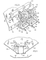
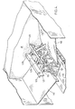
- FIGs. 3 and 4 are fragmentary perspective views of a hopper illustrating a preferred arrangement for preventing the formation of athwardship arches of material. Similar reference numerals, but raised by 100, identify similar parts to Figs. 1 and 2.
- This device is made up of a pair of spaced-apart elongated divider or baffle plates 121 mounted in the position shown relative to the walls of the hopper and the outlets.
- the plates 121 form between them a central elongated vertical channel within the cargo M of particulate material, flanked by lateral channels.
- Each plate 121 is preferably provided, extending outward from its upper edge, with a flange 123 constituting a pressure shield.
- This flange 123 may have a short downwardly extending flange 123a which serves to stiffen the flange to prevent it from buckling.
- the gates 120 are preferably mounted on arms 130, pivotally mounted as at 135 on cross-bars 129 extending between the plates 121.
- the plates 121 are supported from the hopper wall structure 110 by spaced-apart beams 131.
- Each hopper wall 110 extending from a vertical bulkhead 109 to which a short terminal vertical wall 126, which with its opposed wall 126, defines the elongated hopper outlet.
- the arc K indicates the bottom of a main arch of material that would, in the absence of the arch-preventing structure described, form in the mass of finely divided cargo, to prevent the flow of material from the hopper, when the gates are opened. It is to be noted that the plates 121 and 123 intersect the arc K.
- the material in zone T Upon opening of a gate 120, the material in zone T, immediately above the gate, drops onto the conveyor belt 116. This allows the material from the pile in zone R, between the two plates 121, to fall through the void left by the gravitation of the material from zone T and onto the belt 116.
- An arch S may form in the material above zone R (Fig. 6) supported by sloughing, slip, or fracture lines Y and Y 1 .
- each zone M has been protected, all along, from compaction by the weight of the material above it by one of the pressure relieving plates 123.
- the material in zone M is thus kept free to flow into zone T toward the open gates 120, causing a weakening and consequent sagging along the fracture lines Y, Y 1 by the removal of material beneath them. This will cause the arch S to collapse (see Fig. 7). This will, in turn, allow the material in the zone N, between the lines Y, Y 1 and X, X 1 , to flow downward and through the open gates 120.
- the vibrator may be added close to the point where the arch meets the hopper slope, as indicated at V. Then, the vibrator will help to weaken and destroy a segment of any arch which may have formed, urging the whole arch towards collapse.
- the discharge of the cargo from the hopper would be as follows.
- the operator would open one gate (roller track, sliding or basket) type to see if the material would flow properly. If the material arched or rat holed above that gate he would partially close the gate and partially open the adjacent swing gate. If there was still a no-flow situation the operator would partially open the next gate.
- the combined area of each opening of the gates being operated would be determined by the capacity of the conveyor belt being fed. In other words, the sum of the openings would be such as to provide the ideal load for the given conveyor belt.
- the two, three or more lengthwise adjacent openings provide the effect of a single opening of a dimension equal to the distance between the first and last opening which will be greater than the maximum span of the self-supporting arch for that material.
- the self-unloading equipment is such that cargo carried by the vessel can vary widely.
- the cargo can be grain, coal, gypsum, limestone, iron ore, sand, phosphate rock and other powdered, granular and lumpy material. It is important that the unloading mechanism be compatible with the particular cargo. In the event that self-unloading equipment is ineffective to unload the cargo, this can mean a lengthy tie-up of the vessel while shore equipment is employed with the very high cost to the owners of having the ship idle.
- the invention is particularly applicable to hoppered holds of the following preferred characteristics, for containing particulate material.
- the slope of the hopper sides is not steep, so as to attain greater volume and thus storage capacity specially for lighter cargoes. This accelerates the arching problem.
- the slope of the hopper sides usually ranges from about 35° to about 50° from the horizontal.
- a typical head of material in the hopper is 30 to 40 feet.
- Each gate opening or outlet may range from about 3 to about 5 feet in length, with 5 feet preferred and from 41 to 6 feet in width.
- the baffle plates forming the vertical passage are spaced-apart from about 3 to about 5 feet, preferably not more than the width of the hopper outlet.
- the baffle plates may be vertical or may diverge somewhat towards the bottom or may converge slightly toward the top and have a height between 2 and 5 feet.
- the bottom edge of the baffle plates should be 2 to 4 feet above the outlet.
- the pressure shield or laterally extending flange should be from 1 to 2 feet wide and is preferably at the top of the baffle plates and can serve as a walkway, although this horizontal flange can be. part way down on the upper part of the baffle plate.
- the arch-inhibiting structure in a given vessel is aimed at handling the whole range of particulate materials the the vessel is likely to carry. Since each material has its own arch-forming characteristics, the structure must be adapted to handle material having arches up to those with the largest span. Ranges of operative dimensions have been given. But, the precise size and position of the baffle plates may be varied to suit particular circumstances and the optimum has to be determined by trial and error.
- each baffle should be effective to cut across the natural arches of all materials in the range to be handled.
- the bottom edge of each baffle should be spaced far enough above the outlet to provide, outside it, a channel between the baffle and the sidewall of the hopper and wide enough not to unduly restrict the flow of material to the outlet.
- the spacing between the respective baffles should be adequate to provide a central channel of width somewhat comparable to that of the outlet, so as to allow substantial central flow of the material towards the outlet.
- the working surface of the hoppers is preferably covered with plastic sheeting, decreasing the coefficient of friction.
- This covering may be according to the construction disclosed in U.S. Patent 4,528,783, Muir, July 16, 1985.
- the shipboard holds and hoppers described are loaded with conveyor equipment, clams or buckets at dockside. Loading usually takes place to the point where the water reaches the loadline or plimsoll mark on the vessel. With heavy ore, the cargo may reach two-thirds of the height of the hopper. With lighter material, the hoppered holds may be full.
- the cargo is subject to motion and vibration tending to consolidate the powdered materials, as described above. This is accentuated by the relatively shallow slope of shipboard hoppers.
- the weight of the head of material above the outlet contributing, with the vibration, to the further settling and compacting of the material.
- the vessel may pass through a humid zone whereby the cargo picks up moisture. Different materials will respond differently to the forces involved as will the same materials under different conditions. There are many variables. So, the invention is geared to overcoming the most difficult conditions that can be encountered with particulate or lumpy material or combinations.
- the method and apparatus of the invention provides an elongated discharge outlet so equipped with a series of gates that, to all intents and purposes, this outlet is continuous or at least has substantially continuous sections of at least 20 feet (i.e. greater than the span of the largest arch likely to form).
- this outlet is continuous or at least has substantially continuous sections of at least 20 feet (i.e. greater than the span of the largest arch likely to form).
- the tendency to form an arch in the transverse direction, under the shipboard conditions which favour this is dealt with effectively by baffling the contents of the hopper centrally in the longitudinal direction along the entire length of the hopper, which may be up to 100 feet or so.
- hogbacks 14 in Fig. 2
- These hogbacks divide the outlet into several longitudinally aligned sections, each having a length of 3 to 5 feet.
- One gate is separated from the next by an angle iron (48 in Fig. 2).
- the outlet section is three feet long there may be, say, two swing gates and one sliding gate as shown in Fig. 2. If the outlet section is five feet long there may be, say, three swing gates and one sliding gate. It will be evident that the dimensions may be varied to suit the circumstances.
Landscapes
- Engineering & Computer Science (AREA)
- Mechanical Engineering (AREA)
- Auxiliary Methods And Devices For Loading And Unloading (AREA)
- Filling Or Emptying Of Bunkers, Hoppers, And Tanks (AREA)
Applications Claiming Priority (4)
| Application Number | Priority Date | Filing Date | Title |
|---|---|---|---|
| CA477953 | 1985-03-29 | ||
| CA000477953A CA1261296A (en) | 1985-03-29 | 1985-03-29 | Particulate material handling |
| US826200 | 1986-02-05 | ||
| US06/826,200 US4706854A (en) | 1985-03-29 | 1986-02-05 | Particulate material handling |
Publications (2)
| Publication Number | Publication Date |
|---|---|
| EP0196105A2 true EP0196105A2 (de) | 1986-10-01 |
| EP0196105A3 EP0196105A3 (de) | 1988-03-30 |
Family
ID=25670633
Family Applications (1)
| Application Number | Title | Priority Date | Filing Date |
|---|---|---|---|
| EP86104271A Withdrawn EP0196105A3 (de) | 1985-03-29 | 1986-03-27 | Verfahren und Anordnung zum Fördern von Schüttgut |
Country Status (1)
| Country | Link |
|---|---|
| EP (1) | EP0196105A3 (de) |
Cited By (5)
| Publication number | Priority date | Publication date | Assignee | Title |
|---|---|---|---|---|
| CN106867548A (zh) * | 2017-03-30 | 2017-06-20 | 榆林煤化工产业升级技术研发中心 | 一种用以矩形热解炉全区域均匀下料的排料装置及方法 |
| CN111994487A (zh) * | 2020-07-23 | 2020-11-27 | 安徽辰宇机械科技有限公司 | 一种下粮斗及具备该下粮斗的谷物干燥机 |
| CN112136004A (zh) * | 2018-05-14 | 2020-12-25 | 特雷格佩列特烤架有限公司 | 颗粒料斗衬件 |
| CN116675020A (zh) * | 2023-04-24 | 2023-09-01 | 安徽康迪纳电力科技有限责任公司 | 固体颗粒物料给料机及固体颗粒物料配送系统 |
| CN118002512A (zh) * | 2024-01-31 | 2024-05-10 | 中节能建设工程设计院有限公司 | 基于机器视觉的生活固废分类处理方法、装置及存储介质 |
Family Cites Families (7)
| Publication number | Priority date | Publication date | Assignee | Title |
|---|---|---|---|---|
| US1385254A (en) * | 1920-11-11 | 1921-07-19 | Firm Rohm & Haas | Silo or filling-trunk for powdered or granular matter |
| US1663173A (en) * | 1923-12-26 | 1928-03-20 | Louis E W Pioda | Process of and apparatus for controlling the movement of masses of solids of various sizes |
| US2741464A (en) * | 1953-07-07 | 1956-04-10 | Hewitt Robins Inc | Blending bin |
| US3489296A (en) * | 1967-09-11 | 1970-01-13 | Hewitt Robins Inc | Adjustable flow hopper gate |
| US3610485A (en) * | 1970-03-11 | 1971-10-05 | Peerless Trailer And Truck Ser | Dumping-type storage bin with movable interior baffle |
| US4004700A (en) * | 1975-12-22 | 1977-01-25 | Allis-Chalmers Corporation | Hopper gate for self-unloading ships |
| CA1204711A (en) * | 1982-07-29 | 1986-05-20 | Upper Lakes Shipping Ltd. | Swing gates |
-
1986
- 1986-03-27 EP EP86104271A patent/EP0196105A3/de not_active Withdrawn
Cited By (5)
| Publication number | Priority date | Publication date | Assignee | Title |
|---|---|---|---|---|
| CN106867548A (zh) * | 2017-03-30 | 2017-06-20 | 榆林煤化工产业升级技术研发中心 | 一种用以矩形热解炉全区域均匀下料的排料装置及方法 |
| CN112136004A (zh) * | 2018-05-14 | 2020-12-25 | 特雷格佩列特烤架有限公司 | 颗粒料斗衬件 |
| CN111994487A (zh) * | 2020-07-23 | 2020-11-27 | 安徽辰宇机械科技有限公司 | 一种下粮斗及具备该下粮斗的谷物干燥机 |
| CN116675020A (zh) * | 2023-04-24 | 2023-09-01 | 安徽康迪纳电力科技有限责任公司 | 固体颗粒物料给料机及固体颗粒物料配送系统 |
| CN118002512A (zh) * | 2024-01-31 | 2024-05-10 | 中节能建设工程设计院有限公司 | 基于机器视觉的生活固废分类处理方法、装置及存储介质 |
Also Published As
| Publication number | Publication date |
|---|---|
| EP0196105A3 (de) | 1988-03-30 |
Similar Documents
| Publication | Publication Date | Title |
|---|---|---|
| US7008163B2 (en) | Bulk storage bins and methods and apparatus for unloading same | |
| US2717703A (en) | Device for storing pourable solid stock such as shavings, fibers, shreds, and the like | |
| US5526921A (en) | Intersecting bi-directional buckets for a bucket elevator system | |
| US4706854A (en) | Particulate material handling | |
| US4759841A (en) | Produce, rock and debris separator | |
| US4546872A (en) | Discharge control structure for vibratory apparatus | |
| AU595189B2 (en) | Particulate material handling | |
| US3489296A (en) | Adjustable flow hopper gate | |
| EP0240640B1 (de) | Sich nicht zusetzender Austragsförderer | |
| DE1920874B2 (de) | Schwimmende umladeeinrichtung | |
| US5364218A (en) | Bulk material conveyor unloading system for ships | |
| US3002634A (en) | Bulk-cargo carrying ship | |
| JPS5934593B2 (ja) | 突当板とかみ合つているばら荷流ベルト送りゲ−ト | |
| US5372468A (en) | Bulk material unloading system | |
| JP2003341849A (ja) | 土砂等の定量供給装置 | |
| US3536208A (en) | Self-discharging bulk cargo vessel | |
| EP0101959A1 (de) | Schwenkbare Absperrorgane | |
| GB1573820A (en) | Method of and chute for transferring particulate loose material between two levels | |
| US3604573A (en) | System and apparatus for unloading bulk material from a storage enclosure | |
| JP2764231B2 (ja) | 湿潤粉粒体積載用船舶における荷卸し方法 | |
| WO1997033768A1 (en) | Improved bulk material handling vehicle | |
| JPS6341362Y2 (de) | ||
| EP0066846A1 (de) | Gurtförderanlage in einem selbstentladenden Schiff | |
| EP1076024B1 (de) | Schiffsentlader mit Trogkettenförderer | |
| US1430708A (en) | Ship |
Legal Events
| Date | Code | Title | Description |
|---|---|---|---|
| PUAI | Public reference made under article 153(3) epc to a published international application that has entered the european phase |
Free format text: ORIGINAL CODE: 0009012 |
|
| AK | Designated contracting states |
Kind code of ref document: A2 Designated state(s): BE DE FR GB IT NL SE |
|
| PUAL | Search report despatched |
Free format text: ORIGINAL CODE: 0009013 |
|
| AK | Designated contracting states |
Kind code of ref document: A3 Designated state(s): BE DE FR GB IT NL SE |
|
| STAA | Information on the status of an ep patent application or granted ep patent |
Free format text: STATUS: THE APPLICATION IS DEEMED TO BE WITHDRAWN |
|
| 18D | Application deemed to be withdrawn |
Effective date: 19880401 |
|
| RIN1 | Information on inventor provided before grant (corrected) |
Inventor name: POLE, CHARLES D. |