EP0196182A2 - Unterstützungsanordnung - Google Patents
Unterstützungsanordnung Download PDFInfo
- Publication number
- EP0196182A2 EP0196182A2 EP86301847A EP86301847A EP0196182A2 EP 0196182 A2 EP0196182 A2 EP 0196182A2 EP 86301847 A EP86301847 A EP 86301847A EP 86301847 A EP86301847 A EP 86301847A EP 0196182 A2 EP0196182 A2 EP 0196182A2
- Authority
- EP
- European Patent Office
- Prior art keywords
- rail
- bracket
- locating
- aligned
- holes
- Prior art date
- Legal status (The legal status is an assumption and is not a legal conclusion. Google has not performed a legal analysis and makes no representation as to the accuracy of the status listed.)
- Withdrawn
Links
Images


Classifications
-
- E—FIXED CONSTRUCTIONS
- E04—BUILDING
- E04D—ROOF COVERINGS; SKY-LIGHTS; GUTTERS; ROOF-WORKING TOOLS
- E04D3/00—Roof covering by making use of flat or curved slabs or stiff sheets
- E04D3/36—Connecting; Fastening
- E04D3/3601—Connecting; Fastening of roof covering supported by the roof structure with interposition of a insulating layer
- E04D3/3602—The fastening means comprising elongated profiles installed in or on the insulation layer
-
- E—FIXED CONSTRUCTIONS
- E04—BUILDING
- E04D—ROOF COVERINGS; SKY-LIGHTS; GUTTERS; ROOF-WORKING TOOLS
- E04D3/00—Roof covering by making use of flat or curved slabs or stiff sheets
- E04D3/36—Connecting; Fastening
- E04D3/3608—Connecting; Fastening for double roof covering or overroofing
-
- E—FIXED CONSTRUCTIONS
- E04—BUILDING
- E04F—FINISHING WORK ON BUILDINGS, e.g. STAIRS, FLOORS
- E04F13/00—Coverings or linings, e.g. for walls or ceilings
- E04F13/07—Coverings or linings, e.g. for walls or ceilings composed of covering or lining elements; Sub-structures therefor; Fastening means therefor
- E04F13/08—Coverings or linings, e.g. for walls or ceilings composed of covering or lining elements; Sub-structures therefor; Fastening means therefor composed of a plurality of similar covering or lining elements
- E04F13/0889—Coverings or linings, e.g. for walls or ceilings composed of covering or lining elements; Sub-structures therefor; Fastening means therefor composed of a plurality of similar covering or lining elements characterised by the joints between neighbouring elements, e.g. with joint fillings or with tongue and groove connections
- E04F13/0892—Coverings or linings, e.g. for walls or ceilings composed of covering or lining elements; Sub-structures therefor; Fastening means therefor composed of a plurality of similar covering or lining elements characterised by the joints between neighbouring elements, e.g. with joint fillings or with tongue and groove connections with means for aligning the outer surfaces of the covering elements
Definitions
- the present invention relates to support systems for use for example with walls or roofs.
- Walls and roofs for factory or warehouse buildings have been proposed consisting of a double skin of cladding material separated by a plurality of Z-shaped rails and with the space between the two skins filled with a thermally insulating material.
- a support system comprising a pair of U-shaped brackets arranged to be mounted in alignment with each other and a spanning rail of inverted U-shaped cross-section, locating means for locating one of said pair of brackets and said rail being in predetermined nested configuration one within the other, and means securing each bracket with the rail to provide a rigid composite structure of generally rectangular cross-section.
- a support system comprising a plurality of U-shaped brackets, each bracket having at least one opening in its base by means of.which the bracket can be secured to a supporting structure, each bracket having a pair of aligned through holes, one hole in each side wall of the bracket, and a locating hole in each side wall located between the base and each through hole, each locating hole being spaced at a predetermined distance from its corresponding through hole; and a plurality of rails of inverted U-shaped configuration, one end of each rail being arranged to make nested engagement with a said bracket, each said end of the rail having a pair of aligned through holes, one hole in each side wall, each through hole being located at said predetermined distance from the free edge of the side wall whereby when a locating member is made to engage said aligned locating holes of the bracket and the free edges of the rail are rested on the locating member, the aligned through holes of the bracket will be in alignment with the aligned through holes of the rail to enable
- a support system comprising a pair of U-shaped brackets arranged to be mounted in alignment with each other, a spanning rail of inverted U-shaped cross-section, one of said pair of brackets and said rail being nested one within the other, and an inverted U-shaped clamp member for each bracket, each said clamp member being arranged to straddle said rail and to be secured to a corresponding bracket to provide a rigid composite structure of generally rectagular configuration.
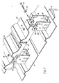
- the roofing system shown in Figure 1 includes a pluralty of generally parallel beams 2 (only one shown) on which a plurality of sheets 4 of cladding are supported to form an inner skin.
- a plurality of U-shaped brackets 6 are mounted at regular intervals on the sheets 4 to extend in rows directly above the beams 2.
- Each bracket is secured by fasteners 8 to the beam so that they are both rigidly secured to the beams 2 and clamp the sheets 4 against the beams 2.
- each row is aligned to receive a series of aligned rails 10.
- Each rail 10 is of inverted U-shaped cross-section and the end portion of each rail 10 is arranged to make nested engagement with a corresponding bracket 6.
- the rails 10 are arranged to be secured to the U-shaped brackets by means of nuts 14 and bolts 12.
- a plurality of sheets of cladding 16 are secured to the rails 10 by fasteners 18 to form the . outer skin of the roof.
- the spacing between the inner and outer skins is advantageously filled with thermally insulating material.
- the fasteners 8 and 18 preferably incorporate a washer or seal to prevent the ingress of water or water vapour to the space between the two skins.
- each bracket 6 can be seen more clearly from Figures 2, 3 and 4.
- a pair of L-shaped ribs 20 are formed on opposite sides of the brackets 6. These ribs 20 act to strengthen the bracket and to resist its deformation.
- each side wall is provided with a pair of locating openings 26.
- a horizontally extending elongate slot 28 is provided a predetermined spacing above each locating opening 26.
- each rail 10 is of generally inverted U-shaped configuration.
- the lower extremity of each side of the rail is folded over and bent inwardly to provide a pair of inwardly directed flanges 30.
- each side portion adjacent each end of the rail there is provided a horizontally extending slot 32.
- the spacing between the lower extremity of the slot 32 and the underside of the flange 30 is arranged to be equal to the spacing between the lower extremity of the slot 28 in the bracket 6 and the upper extremity of the corresponding locating hole 26.
- Each row of brackets 6 is secured to a corresponding beam 2 with the centres of the brackets being spaced at regular intervals and with each interval corresponding to the length of a rail 10; the sheets 4 being located between the brackets 6 and the beam 2.
- a pad (not shown) of thermally insulating material, for example of plastics, is placed between each bracket and the beam to define a thermal break.
- a bolt 12 is passed through each pair of aligned locating openings 26 in each bracket.
- Each rail 10 which is intended to be supported between a pair of brackets is lowered with opposite ends in nesting engagement with respective brackets until the flanges 30 rest on respective bolts 12.
- each rail 10 with each bracket defines a box like structure which provides a rigid and sturdy support for the outer skin of the building.
- the inverted U-shaped rail nested within the U-shaped bracket provides a means by which the two components can be located and their relative positions adjusted just prior to clamping.
- the openings 26 can be omitted and the walls of the brackets 6 deformed to form inwardly projecting dimples or cut and then deformed to define inwardly projecting lands. In this way the rail could be made to rest on the dimples-or lands so that the aligned slots 28 and 32 would be in the same horizontal plane
- the two inwardly extending flanges 30 of the rail can be replaced by outwardly extending flanges and the rail 10 made slightly wider so that the bracket 6 can be nested within the rail 10.
- brackets 6 and the rails 10 are steel or aluminium.
- the rails When supplied in kit form the rails can be supplied in a plurality of different lengths to provide different spans as required.
- an auxiliary inverted U-shaped member (not shown) may be used.
- the bracket is then bolted on to the top of this auxiliary inverted U-shaped member and the auxiliary U-shaped member is provided with outwardly directed feet which in turn are bolted to the beam 2.
- a single bolt can be used to bolt both the inverted U-shaped member and the bracket to the beam 2. In this way the spacing between the skins can be increased by the height of the auxiliary inverted U-shaped member.
- the system includes a plurality of parallel beams 2 (only one shown) on which a plurality of sheets 4 of the cladding are supported to form an inner skin.
- a plurality of U-ehaped brackets 6 are mounted at regular intervals on the sheet 4 to extend in rows directly above the beams 2.
- Each bracket is secured by fasteners 8 to the beam to both rigidly clamp the sheet 4 and bracket 6 against the beam 2.
- the U-shaped bracket 6 is similar to that described in conjunction with Figure 1 except that a third locating hole 26A is provided in each side wall between the existing two holes 26.
- each row is aligned to receive a series of rails 110.
- Each rail 110 is similar to the rail 10 of Figure 1 except that the horizontally extending end slots are omitted.
- an inverted U-shaped clamp member 50 is provided in order to secure the rail to the bracket 6 .
- the clamp member 50 has a pair of spaced downwardly depending arms 56. The spacing between the arms 56 is such as to accommodate the rail 110 and also be accommodated between the arms of the bracket 6.
- the lower portion of each arm 56 has a generally inverted V-shaped recess 52 flanked on each side by an opening 54.
- the upper extremity of the recess 52 and the two openings lie along a common line and are spaced from one another by the same distances as that by which the three holes 26, 26A and 26 in each arm of the bracket 6 are spaced. In a preferred form the upper extremity of the recess lies fractionally above the common line.
- a bolt 12A is fed through the pair of aligned holes 26A and 26A in the bracket 6 and a corresponding nut 14A is loosely screw threadedly fastened to the free end of the bolt 12A.
- the rail 110 is then lowered between the arms of the bracket 6 until it rests on the bolt 12A.
- the rail 110 can then be adjusted longitudinally as required.
- the inverted clamp member 50 is then placed over the rail 110 at the point where the rail passes through the bracket 6 and lowered so that its arms 56 pass between the rail 110 and the side wall of the bracket 6 until the bolt 12A is engaged by the reccesses 52.
- each inverted V-shaped recess does not lie vertically above the bolt 12A then downward pressure applied to the clamp member 50 will produce a cam action between each recess 52 and the bolt 12A to shift the clamp member 50 longitudinally of the rail 110 until the bolt 12A becomes lodged in the apex. This action ensures perfect alignment between the openings 54 in the clamp member 50 and the holes 26 in the bracket 6. (see Figure 8).
- the rail 110 is thus imprisoned between the bracket 6 and its co-operating clamp member 50.
- the rails do not need to be supplied in specific discrete lengths but can be cut to size from longer lengths as required.
- At least the bolt 12A carries the burden consisting of the weight of the rail and any load it may have to bear, while the two bolts 12 and 12 will act to resist the burden of upward forces applied to the rail, for example by wind.
- the clamp member 50 is dimensioned to be a tight fit between the bracket 6 and the rail 110.
- the action of the clamp member 50 upon insertion between the bracket 6 and the rail 110 should be to spring the walls of the bracket 6 slightly apart. In this way the walls of the bracket 6 will be biassed inwardly against the clamp member 50 and the walls of the rail 110 will be biassed outwardly against the clamp member 50.
Landscapes
- Engineering & Computer Science (AREA)
- Architecture (AREA)
- Civil Engineering (AREA)
- Structural Engineering (AREA)
- Mechanical Engineering (AREA)
- Roof Covering Using Slabs Or Stiff Sheets (AREA)
- Tents Or Canopies (AREA)
Applications Claiming Priority (2)
| Application Number | Priority Date | Filing Date | Title |
|---|---|---|---|
| GB858507191A GB8507191D0 (en) | 1985-03-20 | 1985-03-20 | Support system |
| GB8507191 | 1985-03-20 |
Publications (2)
| Publication Number | Publication Date |
|---|---|
| EP0196182A2 true EP0196182A2 (de) | 1986-10-01 |
| EP0196182A3 EP0196182A3 (de) | 1987-08-12 |
Family
ID=10576304
Family Applications (1)
| Application Number | Title | Priority Date | Filing Date |
|---|---|---|---|
| EP86301847A Withdrawn EP0196182A3 (de) | 1985-03-20 | 1986-03-14 | Unterstützungsanordnung |
Country Status (3)
| Country | Link |
|---|---|
| US (1) | US4691491A (de) |
| EP (1) | EP0196182A3 (de) |
| GB (2) | GB8507191D0 (de) |
Cited By (5)
| Publication number | Priority date | Publication date | Assignee | Title |
|---|---|---|---|---|
| FR2661931A1 (fr) * | 1990-05-14 | 1991-11-15 | Etanco Lr | Element de fixation pour couverture ondulee utilisee dans les batiments divers. |
| WO1999054569A1 (en) * | 1998-04-22 | 1999-10-28 | Ward Building Components Limited | A support system |
| EP2194208A1 (de) * | 2008-12-04 | 2010-06-09 | Mage Ag | Wandhalter für Fassadenplatten |
| US11466457B2 (en) | 2019-08-13 | 2022-10-11 | Roof Hugger, Llc | Reinforced notched sub-purlin |
| EP3959390A4 (de) * | 2019-04-24 | 2023-01-11 | Saint-Gobain Placo | Versteifung für bauelemente |
Families Citing this family (47)
| Publication number | Priority date | Publication date | Assignee | Title |
|---|---|---|---|---|
| US5857292A (en) * | 1979-11-13 | 1999-01-12 | Harold Simpson, Inc. | Roof support apparatus |
| US5005323A (en) * | 1982-05-14 | 1991-04-09 | Harold Simpson, Inc. | Apparatus for securing a roofing support spacer to underlying support structures |
| US4924644A (en) * | 1988-05-03 | 1990-05-15 | Lewis David L | Construction board grid system with imprint and method of using same |
| US5911663A (en) * | 1990-11-05 | 1999-06-15 | Eidson; Carson J. | Support clip for roofing panels and associated system |
| US5127205A (en) * | 1990-11-05 | 1992-07-07 | Eidson Carson J | Support clip for roofing panels and associated system |
| GB9305946D0 (en) * | 1993-03-23 | 1993-05-12 | Stramit Ind | Roof or wall supports |
| US6324810B1 (en) * | 1994-02-02 | 2001-12-04 | Thomas Thompson | Retrofit hurricane and earthquake protection |
| WO1996007803A1 (en) * | 1994-09-08 | 1996-03-14 | Non-Compact, Inc. | System for mounting building panels |
| US6171042B1 (en) * | 1997-12-19 | 2001-01-09 | Illinois Tool Works Inc. | Hardened steel pin, pin and washer fastener, washer for fastener, and pin-making method |
| US6240682B1 (en) * | 1998-10-19 | 2001-06-05 | V.P. Buildings, Inc. | Roof bracket |
| US6374554B1 (en) * | 2000-03-22 | 2002-04-23 | Kelley Company, Inc. | Vehicle shelter |
| US6688069B2 (en) * | 2000-07-24 | 2004-02-10 | Unimast Incorporated | Vertical slide clip |
| US6907701B2 (en) * | 2001-06-07 | 2005-06-21 | Gary Edward Smith | Steel roofing panel support |
| GB0123515D0 (en) * | 2001-10-01 | 2001-11-21 | Atkinson Bryan | Roofing fixing apparatus |
| DE60303740T2 (de) * | 2002-01-30 | 2006-10-12 | Architectural Profiles Ltd., Reading | Verkleidung |
| US7533508B1 (en) * | 2002-03-12 | 2009-05-19 | The Steel Network, Inc. | Connector for connecting building components |
| US8387321B2 (en) * | 2002-03-12 | 2013-03-05 | The Steel Network, Inc. | Connector for connecting building components |
| US7574842B2 (en) * | 2002-04-11 | 2009-08-18 | Schott Solar, Inc. | Apparatus for mounting photovoltaic power generating systems on buildings |
| WO2003087493A1 (en) * | 2002-04-11 | 2003-10-23 | Rwe Schott Solar Inc. | Apparatus and method for mounting photovoltaic power generating systems on buildings |
| PE20050100A1 (es) * | 2003-04-08 | 2005-04-29 | Ubilla Jose Rojas | Estructura soportante para el cielo de una construccion habitable que se construye con tres tipos de elementos estructurales unidos entre si por tornillos |
| AU2004324972A1 (en) * | 2004-11-17 | 2006-05-26 | Jr Consulting & Drafting Pty Limited | Framing members and their inter-connection |
| GB2421254B (en) * | 2004-12-14 | 2010-03-03 | Kingspan Res & Dev Ltd | A composite cladding |
| US7987647B2 (en) * | 2006-10-04 | 2011-08-02 | Robert John Rymell | Re-roofing system and a method of installation |
| GB2446451B (en) * | 2007-02-07 | 2012-10-03 | Derek Frank Price | Method of repairing a building |
| ES2452832T3 (es) * | 2007-05-17 | 2014-04-02 | Kingspan Holdings (Irl) Limited | Sistema de soporte para montar elementos de fachada de edificio en un armazón |
| US8327590B2 (en) | 2009-07-22 | 2012-12-11 | Gino Ray | Roofing system support assembly |
| US8061087B2 (en) * | 2009-07-22 | 2011-11-22 | Gino Ray | Retrofit framing system for metal roof |
| JP4688951B1 (ja) * | 2009-12-25 | 2011-05-25 | シャープ株式会社 | 構造物設置架台、構造物設置用支持具、及び太陽光発電システム |
| US8833025B2 (en) | 2011-01-04 | 2014-09-16 | Advanced Architectural Products, Llc | Polymer-based bracket system for exterior cladding |
| US8826620B2 (en) | 2011-01-04 | 2014-09-09 | Advanced Architectural Products, Llc | Polymer-based bracket system for metal panels |
| US9151052B2 (en) | 2011-01-04 | 2015-10-06 | Advanced Architectural Products, Llc | Insulation system for buildings |
| US20130146554A1 (en) * | 2011-06-15 | 2013-06-13 | Jason Berry | Solar module mounting apparatus |
| US8955276B2 (en) * | 2012-01-25 | 2015-02-17 | Steven James Wall | Raised flooring apparatus and system |
| CN104870729B (zh) * | 2012-11-16 | 2018-07-24 | 蓝野钢铁有限公司 | 用于屋顶包覆板的端部搭接系统 |
| CA3117929C (en) * | 2013-02-11 | 2024-05-21 | Advanced Architectural Products, Llc | Polymer-based bracket system for exterior cladding |
| GB2517479A (en) * | 2013-08-22 | 2015-02-25 | Warren Paul Green | Safety Device |
| US10378164B2 (en) | 2015-11-23 | 2019-08-13 | Contech Engineered Solutions LLC | Reinforcement system and method for corrugated plate structures |
| WO2017210363A1 (en) | 2016-05-31 | 2017-12-07 | Advanced Architectural Products, Llc | Insulating structure for buildings |
| WO2017214479A1 (en) | 2016-06-09 | 2017-12-14 | Advanced Architectural Products, Llc | Insulating system for buildings |
| EP3372845B1 (de) * | 2017-03-08 | 2023-08-02 | SKF Aerospace France S.A.S. | Beschlag mit verbesserter nabenstruktur |
| US20190100920A1 (en) * | 2017-10-03 | 2019-04-04 | Advanced Architectural Products, Llc | Roof Construction |
| US11536034B2 (en) | 2020-03-26 | 2022-12-27 | Nucor Corporation | Insulated roof systems, support members thereof, and method of installing |
| USD1053389S1 (en) | 2020-03-26 | 2024-12-03 | Nucor Corporation | Support member for roof panel offset |
| KR102470244B1 (ko) * | 2020-04-22 | 2022-11-23 | 정민시 | 천장 경량철골 구조 메인 캐리어의 장착수단 |
| US11566421B2 (en) | 2020-06-25 | 2023-01-31 | Advanced Architectural Products, Llc | Adjustable support system for a building structure and a wall structure having an adjustable support system |
| US11542702B2 (en) | 2020-06-25 | 2023-01-03 | Advanced Architectural Products, Llc | Adjustable support system for a building structure and a wall structure having an adjustable support system |
| US11739528B1 (en) * | 2022-03-01 | 2023-08-29 | Jesus Lara | Roofing system |
Family Cites Families (20)
| Publication number | Priority date | Publication date | Assignee | Title |
|---|---|---|---|---|
| US1699557A (en) * | 1924-03-10 | 1929-01-22 | Roy V Yeager | Screed anchoring and leveling device |
| US2013101A (en) * | 1934-03-30 | 1935-09-03 | Inglee Lewis | Furring clip |
| BE662114A (de) * | 1964-04-11 | |||
| GB1134570A (en) * | 1965-12-02 | 1968-11-27 | Structo System Of Canada Ltd | Improvements in or relating to constructional components for use in framework and shelving systems and such systems and frameworks |
| US3477189A (en) * | 1967-02-20 | 1969-11-11 | Anthes Imperial Ltd | Load supporting structure |
| ES227791Y (es) * | 1976-04-14 | 1977-11-01 | Falso techo. | |
| US4081938A (en) * | 1976-12-13 | 1978-04-04 | Ralph Bertacchi | Standoff insulated panel mounting |
| DE2801642A1 (de) * | 1978-01-16 | 1979-07-19 | Ulrich Kleta | Unterkonstruktion fuer den hochbau zur aufnahme von vorhangfassaden u.dgl. |
| DE2806872A1 (de) * | 1978-02-17 | 1979-08-23 | Walter Haase | Fassadenunterkonstruktion |
| DE2814095C3 (de) * | 1978-04-01 | 1982-12-09 | Fa. Helmut Stangel u. Rainer Wichert Decken- und Akustikbau, 5800 Hagen | Verbinder für zwei sich kreuzende, übereinanderliegende Schienen |
| US4248021A (en) * | 1979-08-22 | 1981-02-03 | H. H. Robertson Company | Support means for wall or roof structure |
| NZ197507A (en) * | 1980-07-02 | 1984-11-09 | Stirling Wilson M | Slidable clip:method of panelling using clips,reentrant flanged channels,and t & g boards |
| GB2081332A (en) * | 1980-07-18 | 1982-02-17 | Fortelite Ltd | Clamp for supports for a suspended ceiling |
| DE3032359C2 (de) * | 1980-08-28 | 1986-06-12 | Hermann 6380 Bad Homburg Loos | Unterkonstruktion zur Befestigung einer Wandbekleidung |
| GB2089864A (en) * | 1980-12-15 | 1982-06-30 | Norpee Construction Engineers | Overcladding Structure for a Roof |
| GB2117026A (en) * | 1982-03-19 | 1983-10-05 | Conder International Ltd | Roof underlining and method of erection |
| GB2120702B (en) * | 1982-05-25 | 1985-09-04 | Hunter Douglas Ind Bv | Clip for wall or ceiling panel structure |
| GB2134557A (en) * | 1983-02-02 | 1984-08-15 | Anderson Construction Company | Adjustable floor prop |
| FR2542393B1 (fr) * | 1983-03-11 | 1987-10-09 | Gissinger Bernard | Piece porteuse de pannes pour la realisation de couvertures ou bardages doubles |
| GB8402435D0 (en) * | 1984-01-31 | 1984-03-07 | Huei Long Chen | Mounting structure for ceiling panels |
-
1985
- 1985-03-20 GB GB858507191A patent/GB8507191D0/en active Pending
-
1986
- 1986-03-14 EP EP86301847A patent/EP0196182A3/de not_active Withdrawn
- 1986-03-14 GB GB08606356A patent/GB2172626B/en not_active Expired
- 1986-03-19 US US06/841,285 patent/US4691491A/en not_active Expired - Fee Related
Cited By (6)
| Publication number | Priority date | Publication date | Assignee | Title |
|---|---|---|---|---|
| FR2661931A1 (fr) * | 1990-05-14 | 1991-11-15 | Etanco Lr | Element de fixation pour couverture ondulee utilisee dans les batiments divers. |
| WO1999054569A1 (en) * | 1998-04-22 | 1999-10-28 | Ward Building Components Limited | A support system |
| EP2194208A1 (de) * | 2008-12-04 | 2010-06-09 | Mage Ag | Wandhalter für Fassadenplatten |
| EP3959390A4 (de) * | 2019-04-24 | 2023-01-11 | Saint-Gobain Placo | Versteifung für bauelemente |
| US11466457B2 (en) | 2019-08-13 | 2022-10-11 | Roof Hugger, Llc | Reinforced notched sub-purlin |
| US11761212B2 (en) | 2019-08-13 | 2023-09-19 | Roof Hugger, Llc | Reinforced notched sub-purlin |
Also Published As
| Publication number | Publication date |
|---|---|
| US4691491A (en) | 1987-09-08 |
| GB2172626B (en) | 1989-02-15 |
| GB8606356D0 (en) | 1986-04-23 |
| GB2172626A (en) | 1986-09-24 |
| GB8507191D0 (en) | 1985-04-24 |
| EP0196182A3 (de) | 1987-08-12 |
Similar Documents
| Publication | Publication Date | Title |
|---|---|---|
| US4691491A (en) | Support systems | |
| US4223667A (en) | Apparatus for supporting solar collectors on a building | |
| US4232845A (en) | On-site modular support systems for supporting cables, conduit and the like | |
| US7752823B2 (en) | Purlin bracing system for metal building roof | |
| US3756567A (en) | Longitudinally adjustable interlocking railing construction | |
| US6079174A (en) | Wall panel having movable cap | |
| US20100275549A1 (en) | Clips for connecting panels and cross members without visual reference | |
| HU181229B (en) | Sheet for sheeting of working pit | |
| CA2231483A1 (en) | Joist bracing apparatus | |
| US4413361A (en) | Deck and fence structure for above ground swimming pools | |
| CA2083034A1 (en) | Seismic brace for electric cable tray | |
| US2981383A (en) | Interlocking i-beam for roof and side wall structure | |
| US6276668B1 (en) | Roof safety bracket system | |
| US5092087A (en) | Skylight framework | |
| US3968616A (en) | Decking beam assembly | |
| EP4184018A1 (de) | Dachbefestigungskonsole | |
| US4574549A (en) | Adjustable roof insulation system | |
| EP2578775B1 (de) | Verankerung einer Sicherungsleine | |
| US5345729A (en) | Support for tamper proof securing light fixture on suspended ceiling panel | |
| DE2927164A1 (de) | Fassadenverkleidung | |
| EP0222456A2 (de) | Lüftungsvorrichtung mit Jalousiewänden | |
| US6390725B1 (en) | Fastener for permanently securing composite gratings to structural members | |
| JPH053614Y2 (de) | ||
| CH711544A1 (de) | Solarmodul-Tragvorrichtung. | |
| AU677527B2 (en) | Support structure for roof safety system and means for fastening same |
Legal Events
| Date | Code | Title | Description |
|---|---|---|---|
| PUAI | Public reference made under article 153(3) epc to a published international application that has entered the european phase |
Free format text: ORIGINAL CODE: 0009012 |
|
| AK | Designated contracting states |
Kind code of ref document: A2 Designated state(s): AT BE CH DE FR GB IT LI LU NL SE |
|
| PUAL | Search report despatched |
Free format text: ORIGINAL CODE: 0009013 |
|
| AK | Designated contracting states |
Kind code of ref document: A3 Designated state(s): AT BE CH DE FR GB IT LI LU NL SE |
|
| 17P | Request for examination filed |
Effective date: 19880202 |
|
| 17Q | First examination report despatched |
Effective date: 19890220 |
|
| STAA | Information on the status of an ep patent application or granted ep patent |
Free format text: STATUS: THE APPLICATION IS DEEMED TO BE WITHDRAWN |
|
| 18D | Application deemed to be withdrawn |
Effective date: 19890911 |
|
| RIN1 | Information on inventor provided before grant (corrected) |
Inventor name: LILLEY, RAYMOND ALLEN CHARLES |