EP0196221A2 - Verfahren zur Herstellung von Keremik-Kompositmaterialien - Google Patents
Verfahren zur Herstellung von Keremik-Kompositmaterialien Download PDFInfo
- Publication number
- EP0196221A2 EP0196221A2 EP86302216A EP86302216A EP0196221A2 EP 0196221 A2 EP0196221 A2 EP 0196221A2 EP 86302216 A EP86302216 A EP 86302216A EP 86302216 A EP86302216 A EP 86302216A EP 0196221 A2 EP0196221 A2 EP 0196221A2
- Authority
- EP
- European Patent Office
- Prior art keywords
- ceramic
- components
- eutectic
- brazing
- component
- Prior art date
- Legal status (The legal status is an assumption and is not a legal conclusion. Google has not performed a legal analysis and makes no representation as to the accuracy of the status listed.)
- Granted
Links
Images

Classifications
-
- B—PERFORMING OPERATIONS; TRANSPORTING
- B23—MACHINE TOOLS; METAL-WORKING NOT OTHERWISE PROVIDED FOR
- B23K—SOLDERING OR UNSOLDERING; WELDING; CLADDING OR PLATING BY SOLDERING OR WELDING; CUTTING BY APPLYING HEAT LOCALLY, e.g. FLAME CUTTING; WORKING BY LASER BEAM
- B23K35/00—Rods, electrodes, materials, or media, for use in soldering, welding, or cutting
- B23K35/22—Rods, electrodes, materials, or media, for use in soldering, welding, or cutting characterised by the composition or nature of the material
- B23K35/24—Selection of soldering or welding materials proper
- B23K35/30—Selection of soldering or welding materials proper with the principal constituent melting at less than 1550°C
- B23K35/3006—Ag as the principal constituent
-
- C—CHEMISTRY; METALLURGY
- C04—CEMENTS; CONCRETE; ARTIFICIAL STONE; CERAMICS; REFRACTORIES
- C04B—LIME, MAGNESIA; SLAG; CEMENTS; COMPOSITIONS THEREOF, e.g. MORTARS, CONCRETE OR LIKE BUILDING MATERIALS; ARTIFICIAL STONE; CERAMICS; REFRACTORIES; TREATMENT OF NATURAL STONE
- C04B37/00—Joining burned ceramic articles with other burned ceramic articles or other articles by heating
- C04B37/003—Joining burned ceramic articles with other burned ceramic articles or other articles by heating by means of an interlayer consisting of a combination of materials selected from glass, or ceramic material with metals, metal oxides or metal salts
- C04B37/006—Joining burned ceramic articles with other burned ceramic articles or other articles by heating by means of an interlayer consisting of a combination of materials selected from glass, or ceramic material with metals, metal oxides or metal salts consisting of metals or metal salts
-
- C—CHEMISTRY; METALLURGY
- C04—CEMENTS; CONCRETE; ARTIFICIAL STONE; CERAMICS; REFRACTORIES
- C04B—LIME, MAGNESIA; SLAG; CEMENTS; COMPOSITIONS THEREOF, e.g. MORTARS, CONCRETE OR LIKE BUILDING MATERIALS; ARTIFICIAL STONE; CERAMICS; REFRACTORIES; TREATMENT OF NATURAL STONE
- C04B37/00—Joining burned ceramic articles with other burned ceramic articles or other articles by heating
- C04B37/02—Joining burned ceramic articles with other burned ceramic articles or other articles by heating with metallic articles
- C04B37/023—Joining burned ceramic articles with other burned ceramic articles or other articles by heating with metallic articles characterised by the interlayer used
- C04B37/026—Joining burned ceramic articles with other burned ceramic articles or other articles by heating with metallic articles characterised by the interlayer used consisting of metals or metal salts
-
- H—ELECTRICITY
- H05—ELECTRIC TECHNIQUES NOT OTHERWISE PROVIDED FOR
- H05B—ELECTRIC HEATING; ELECTRIC LIGHT SOURCES NOT OTHERWISE PROVIDED FOR; CIRCUIT ARRANGEMENTS FOR ELECTRIC LIGHT SOURCES, IN GENERAL
- H05B3/00—Ohmic-resistance heating
- H05B3/02—Details
- H05B3/03—Electrodes
-
- C—CHEMISTRY; METALLURGY
- C04—CEMENTS; CONCRETE; ARTIFICIAL STONE; CERAMICS; REFRACTORIES
- C04B—LIME, MAGNESIA; SLAG; CEMENTS; COMPOSITIONS THEREOF, e.g. MORTARS, CONCRETE OR LIKE BUILDING MATERIALS; ARTIFICIAL STONE; CERAMICS; REFRACTORIES; TREATMENT OF NATURAL STONE
- C04B2237/00—Aspects relating to ceramic laminates or to joining of ceramic articles with other articles by heating
- C04B2237/02—Aspects relating to interlayers, e.g. used to join ceramic articles with other articles by heating
- C04B2237/12—Metallic interlayers
- C04B2237/125—Metallic interlayers based on noble metals, e.g. silver
-
- C—CHEMISTRY; METALLURGY
- C04—CEMENTS; CONCRETE; ARTIFICIAL STONE; CERAMICS; REFRACTORIES
- C04B—LIME, MAGNESIA; SLAG; CEMENTS; COMPOSITIONS THEREOF, e.g. MORTARS, CONCRETE OR LIKE BUILDING MATERIALS; ARTIFICIAL STONE; CERAMICS; REFRACTORIES; TREATMENT OF NATURAL STONE
- C04B2237/00—Aspects relating to ceramic laminates or to joining of ceramic articles with other articles by heating
- C04B2237/02—Aspects relating to interlayers, e.g. used to join ceramic articles with other articles by heating
- C04B2237/12—Metallic interlayers
- C04B2237/126—Metallic interlayers wherein the active component for bonding is not the largest fraction of the interlayer
- C04B2237/127—The active component for bonding being a refractory metal
-
- C—CHEMISTRY; METALLURGY
- C04—CEMENTS; CONCRETE; ARTIFICIAL STONE; CERAMICS; REFRACTORIES
- C04B—LIME, MAGNESIA; SLAG; CEMENTS; COMPOSITIONS THEREOF, e.g. MORTARS, CONCRETE OR LIKE BUILDING MATERIALS; ARTIFICIAL STONE; CERAMICS; REFRACTORIES; TREATMENT OF NATURAL STONE
- C04B2237/00—Aspects relating to ceramic laminates or to joining of ceramic articles with other articles by heating
- C04B2237/30—Composition of layers of ceramic laminates or of ceramic or metallic articles to be joined by heating, e.g. Si substrates
- C04B2237/32—Ceramic
- C04B2237/34—Oxidic
- C04B2237/343—Alumina or aluminates
-
- C—CHEMISTRY; METALLURGY
- C04—CEMENTS; CONCRETE; ARTIFICIAL STONE; CERAMICS; REFRACTORIES
- C04B—LIME, MAGNESIA; SLAG; CEMENTS; COMPOSITIONS THEREOF, e.g. MORTARS, CONCRETE OR LIKE BUILDING MATERIALS; ARTIFICIAL STONE; CERAMICS; REFRACTORIES; TREATMENT OF NATURAL STONE
- C04B2237/00—Aspects relating to ceramic laminates or to joining of ceramic articles with other articles by heating
- C04B2237/30—Composition of layers of ceramic laminates or of ceramic or metallic articles to be joined by heating, e.g. Si substrates
- C04B2237/40—Metallic
- C04B2237/405—Iron metal group, e.g. Co or Ni
- C04B2237/406—Iron, e.g. steel
-
- C—CHEMISTRY; METALLURGY
- C04—CEMENTS; CONCRETE; ARTIFICIAL STONE; CERAMICS; REFRACTORIES
- C04B—LIME, MAGNESIA; SLAG; CEMENTS; COMPOSITIONS THEREOF, e.g. MORTARS, CONCRETE OR LIKE BUILDING MATERIALS; ARTIFICIAL STONE; CERAMICS; REFRACTORIES; TREATMENT OF NATURAL STONE
- C04B2237/00—Aspects relating to ceramic laminates or to joining of ceramic articles with other articles by heating
- C04B2237/50—Processing aspects relating to ceramic laminates or to the joining of ceramic articles with other articles by heating
- C04B2237/76—Forming laminates or joined articles comprising at least one member in the form other than a sheet or disc, e.g. two tubes or a tube and a sheet or disc
- C04B2237/765—Forming laminates or joined articles comprising at least one member in the form other than a sheet or disc, e.g. two tubes or a tube and a sheet or disc at least one member being a tube
-
- C—CHEMISTRY; METALLURGY
- C04—CEMENTS; CONCRETE; ARTIFICIAL STONE; CERAMICS; REFRACTORIES
- C04B—LIME, MAGNESIA; SLAG; CEMENTS; COMPOSITIONS THEREOF, e.g. MORTARS, CONCRETE OR LIKE BUILDING MATERIALS; ARTIFICIAL STONE; CERAMICS; REFRACTORIES; TREATMENT OF NATURAL STONE
- C04B2237/00—Aspects relating to ceramic laminates or to joining of ceramic articles with other articles by heating
- C04B2237/50—Processing aspects relating to ceramic laminates or to the joining of ceramic articles with other articles by heating
- C04B2237/84—Joining of a first substrate with a second substrate at least partially inside the first substrate, where the bonding area is at the inside of the first substrate, e.g. one tube inside another tube
Definitions
- This invention relates to the brazing together of certain ceramic components with other ceramic or metal components, and to providing a pressure sealing joint therebetween.
- the invention relates to high pressure electrodes and their manufacture.
- Electrodes may be used for sensing properties of surrounding materials, for example the presence or absence of water in a boiler. Such an electrode may be insulated from a further electrode and a parameter measurement performed between the pair. Where a container is conductive one electrode of the pair may be constituted by the container and regarded as a ground connection. A series of electrodes arranged for resistance to be measured at various levels in a container for example would enable water level in the container to be assessed.
- a suitable electrode could be formed as a steel rod entering the container through a sealed entry port, the seal incorporating an insulator so that the rod is usable as an electrode.
- Insulators which have been employed for this purpose include some ceramic materials such as Aluminium Oxide (A1 2 0 3 ).
- Electrodes are required for example for measurement of boilers operating in excess of 200 bar.
- the electrode In order to withstand such pressure. the electrode must be sealingly bonded to its insulator. Conventional methods of joining metals to ceramics such as by adhesive and by the shrink fitting of a heated metal component have proved inadequate for this purpose and in order to provide such a bond-brazing has been employed, and electrodes having a stainless steel to ceramic seal capable of withstanding test pressures of 450 bar have been made.
- the known process is that of molybdenum/manganese brazing in which a paste containing molybdenum and manganese is applied to the area of the ceramic to be joined and fired to the silica phase of the ceramic. Good bonds may be achieved with ceramics having a grain size averaging about 30 microns and a silica content of about 0.5%. When firing is complete the fired ceramic may be directly electro-plated to allow soldering with conventional soldering alloys.
- a method of brazing a ceramic component to another component including the steps of:-
- a pressure seal between a ceramic component and another component comprising a brazed joint therebetween, the joint being made with a eutectic of substantially the composition disclosed above.
- a seal may be employed in a high pressure electrode.
- the present invention also provides a sensor electrode, having a metal electrode tip insulated from a metal body by virtue of a ceramic spacing member and pressure sealed as hereindescribed.
- the titanium content of the eutectic is restricted dependent upon the silica content of the ceramic.
- the eutectic may be introduced in elemental form, where essentially annular components are to be joined, the material may be introduced by means of washers or annuli of silver and titanium.
- a stainless steel rod electrode 11 has a tip section attached through the agency of a stud 14 threaded into the rod end.
- the rod is surrounded by a stainless steel sheath 15 and spaced apart there from by an insulating collar 16.
- the rod is terminated in a screw type electrical connection 19 to allow electrical connection thereto.
- the sensor is introduced into the body of the boiler through a hole in boiler wall 10, and secured in place by the cooperation of a circular well 18 in the boiler wall, a flange 19 on the sensor sheath and a clamping plate 100. Sealing is afforded by gasket 102.
- Tip section 12 is brazed to the stud 14 and is configured as an extension of the sheath portion 15 but spaced apart therefrom by a ceramic spacer 101, which also serves to provide seperation and insulation from electrode rod 11.
- the sheath 15 is at ground potential by virtue of contact with cylinder wall 10, and rod 11 and electrode tip 14-insulated therefrom so that a measurement may be made, for example an electrode/ground parameter measurement to establish water level as described in UK Patent 1 605 145.
- the ceramic spacer 101 provides a seal between cylinder interior and exterior and may be subject to the full operating pressure of the boiler of for example 200 bar.
- the sealing performance of the spacer 101 is largely determined by the quality of joins 103 and 104 between the spacer 101 and the stainless steel sheath 15 and between the spacer 101 and the electrode tip 12 respectively.
- joins 103, 104 have been brazed using conventional brazing eutectics suitable for brazing stainless steel, such as for example a eutectic of active composition 92.5% silver and 6% copper.
- conventional brazing eutectics suitable for brazing stainless steel such as for example a eutectic of active composition 92.5% silver and 6% copper.
- the ceramic spacer 101 is formed in A1 2 0 3 of purity 99.5%, an average grain size of between 8 and 10 microns, a maximum silica content of 0.2% and density of at least 3.8 gm/cm3.
- the brazing eutectic for joints 103, 104 is made up of 88% silver 5.6% copper and 1% titanium, with about 1.5% residual impurities.
- Joint 105 between tip section 12 and electrode rod stud 14 is a conventional steel to steel braze.
- stud 14 is first screwed into electrode rod 11 and sheath 15 held in place by spacer 16 and securing nuts 106.
- Spacer 101 is placed over the electrode rod 11 and sheath 15 held in place by spacer 16 and securing nuts 106.
- Spacer 101 is placed over the electode rod, followed by tip section 12.
- Brazing eutectic is introduced at joins 103, 104, 105 being eutectic as described above for joins 103, 104, and conventional eutectic for stainless steel to stainless steel brazed joint 105.
- the assembly is then placed in a vacuum furnace for the braze to be made.
- the completed braze secures all parts together and provides a pressure secure sealing joint.
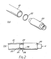
- a ceramic component 20 (Figure 2) is to be brazed to a stainless steel cylinder 21. As the components are brought together a eutectic 22 is introduced therebetween. During brazing the component must be held in the required relationship and urged together along direction U. For example the components may be held vertically in a jig (not shown) and urged together by virtue of the weight of component 20 acting down on cylinder 21.
- Brazing eutectic 22 is introduced as an annulus lightly gripped between the components as they are brought together.
- the annulus may be staightforwardly formed as a single turn of abutting wire.
- the procedure to effect the braze is as follows.
- the components are thoroughly solvent cleaned, for example with Arklone or Freon.
- the components are placed in a vacuum furnace and a vacuum of at least 10 -4 Torr establshed.
- the temperature is increased at a rate of 30°C per minute until a temperature of 750°C is reached. which is maintained for approximately 5 minutes.
- the temperature is further increased to 985°C at the same rate, this temperature also being maintained for 5 minutes.
- the chamber is then allowed to cool slowly down to 750°C, whereupon the vacuum is released and argon gas introduced as a coolant.
- the brazed components may be removed at a temperature below 100°C.
- the brazing eutectic may be formed as a coating of essentially conventional eutectic having a composition of 92.5% silver and 6% copper on a titanium wire , so that the final eutectic wire has a titanium content of about 1% by weight.
- Titanium is known to have a close packed hexagonal structure (the alpha phase), which changes at the crystal transformation temperature of 882°C to a body centred cubic structure (the Beta phase).
- Inherent impurities in commercially 'pure' titanium modify this temperature to approximately 900/950°C and the melting temperature to 1660°C plus or minus 10%.
- the titanium crystal develops an affinity for or with oxide ceramics, and in the presence of a suitable eutectic will migrate to the surface of the ceramic and form the layered compound of metallic oxides as described above, which allows the eutectic to 'wet' the surface of the ceramic and so effect a molecular bond.
- the mutually cohesive layer build up permits bonding of a ceramic to other metals, such as stainless steel and to other ceramics of substantially the same composition.
- the eutectic be introduced in coherent or amalgam form, and in view of the difference in melting temperature of silver and titanium it is not preferred.
- the materials may be introduced as precursors which form the required composition during the brazing cycle.
- separate annuli of silver, copper and titanium in the form of washers stamped from thin sheet, may be introduced.
- a woven or platted braid made up of silver, copper and titanium elemental wires may be used.
- the invention provides a diverting channel 23 formed between ceramic member 20 and metal member 21 which extends therebetween and away from the join, formed between complementary profiled surfaces 24 (of ceramic member 20) and 25 (of metal member 21).
- Eutectic material in channel 21 is not required for a successful joint, its presence merely indicating that excess material has been harmlessly diverted away from sealing surface 26.
- the structure of the ceramic used has a large influence upon the integrity of the finished joint. Almost all aluminium oxide ceramics intended for brazed assemblies are milled and compounded to accommodate the prior art moly/manganese process, which process requires a grain size of say 30 to 50 microns with a silica content of 1.3 to 1.5% to provide a suitable surface glassy phase to which the moly/manganese can be fired.
- This ceramic formulation is generally not satisfactory for the method of the present invention. It has been established that aluminium oxide of 99.5% crystal purity, milled to nominally 30 microns, will after firing at approximately 1700°C contain grains as large as 70 microns due to grain growth during the long firing process, this in turn means that silica-rich areas will develop between adjacent large grains. Where these occur on the surface of the ceramic, in an area to be brazed, the silica is leached out to form a silver silicide within the eutectic. This leaching of the silica phase of the ceramic leaves the alumina grains unsupported, thus creating a weak ceramic surface structure. This is prone to fracture due to the differing thermal coefficients of expansion (and contraction) of the eutectic and metal components during cooling.
- a good aluminium oxide for reaction brazing has a crystal purity of 99.5% a maximum grain size of 20 microns and a silica content not greater than 0.18% and should be iso-statically pressed to provide a uniform density of 3.80 min: grams per cubic centimeter.
- this ceramic has a cross breaking strength in excess of 20 tons per square inch, a hardness value of 84 on the Rockwell 45N scale and the Youngs modulus is 52.7 x 10 lbsF/in .
Landscapes
- Chemical & Material Sciences (AREA)
- Engineering & Computer Science (AREA)
- Ceramic Engineering (AREA)
- Materials Engineering (AREA)
- Structural Engineering (AREA)
- Organic Chemistry (AREA)
- Mechanical Engineering (AREA)
- Ceramic Products (AREA)
- Measuring Fluid Pressure (AREA)
- Compounds Of Unknown Constitution (AREA)
- Glass Compositions (AREA)
- Superconductors And Manufacturing Methods Therefor (AREA)
Priority Applications (1)
| Application Number | Priority Date | Filing Date | Title |
|---|---|---|---|
| AT86302216T ATE51610T1 (de) | 1985-03-27 | 1986-03-26 | Verfahren zur herstellung von keremikkompositmaterialien. |
Applications Claiming Priority (2)
| Application Number | Priority Date | Filing Date | Title |
|---|---|---|---|
| GB8507909 | 1985-03-27 | ||
| GB858507909A GB8507909D0 (en) | 1985-03-27 | 1985-03-27 | Brazing eutectic |
Publications (3)
| Publication Number | Publication Date |
|---|---|
| EP0196221A2 true EP0196221A2 (de) | 1986-10-01 |
| EP0196221A3 EP0196221A3 (en) | 1987-04-22 |
| EP0196221B1 EP0196221B1 (de) | 1990-04-04 |
Family
ID=10576693
Family Applications (1)
| Application Number | Title | Priority Date | Filing Date |
|---|---|---|---|
| EP86302216A Expired EP0196221B1 (de) | 1985-03-27 | 1986-03-26 | Verfahren zur Herstellung von Keremik-Kompositmaterialien |
Country Status (9)
| Country | Link |
|---|---|
| US (1) | US4714189A (de) |
| EP (1) | EP0196221B1 (de) |
| JP (1) | JPS61266365A (de) |
| CN (1) | CN86103134A (de) |
| AT (1) | ATE51610T1 (de) |
| CA (1) | CA1262661A (de) |
| DE (1) | DE3670068D1 (de) |
| GB (2) | GB8507909D0 (de) |
| IN (1) | IN165368B (de) |
Cited By (2)
| Publication number | Priority date | Publication date | Assignee | Title |
|---|---|---|---|---|
| EP0399306A3 (de) * | 1989-05-20 | 1991-01-23 | MAN Gutehoffnungshütte Aktiengesellschaft | Einrichtung zur Abdichtung und Befestigung von Heizleitern an elektrisch beheizten Vakuumöfen |
| EP0868961A1 (de) * | 1997-03-12 | 1998-10-07 | Dowa Mining Co., Ltd. | Keramik-Metall-Verbundsubstrat, Herstellungsverfahren und Hartlotwerkstoff zum Verwenden in diesem Verfahren |
Families Citing this family (12)
| Publication number | Priority date | Publication date | Assignee | Title |
|---|---|---|---|---|
| JPS63139075A (ja) * | 1986-12-02 | 1988-06-10 | 日本碍子株式会社 | セラミックス・金属結合体およびその製造方法 |
| GB8704907D0 (en) * | 1987-03-03 | 1987-04-08 | Schlumberger Electronics Uk | Ceramics |
| JPS6443988A (en) * | 1987-08-11 | 1989-02-16 | Hakusan Seisakusho Kk | Gas lighting arrester and its manufacture |
| GB8818712D0 (en) * | 1988-08-05 | 1988-09-07 | Shell Int Research | Probe |
| US5364010A (en) * | 1990-07-05 | 1994-11-15 | The Morgan Crucible Company, Plc | Joining of metal to ceramic bodies by brazing |
| US6168069B1 (en) * | 1997-07-18 | 2001-01-02 | Endress +Hauser Flowtec Ag | Method of brazing titanium to stainless steel |
| JP4538878B2 (ja) * | 2000-01-19 | 2010-09-08 | 大同特殊鋼株式会社 | 鋼材とチタン材との接合方法 |
| US6513377B1 (en) * | 2000-04-03 | 2003-02-04 | R.E.A. S.N.C. Di Sassi Baudin & C. | Boiler level indicator |
| US7771424B2 (en) * | 2005-03-16 | 2010-08-10 | Starion Instruments | Integrated metalized ceramic heating element for use in a tissue cutting and sealing device |
| CN102216689A (zh) * | 2008-10-23 | 2011-10-12 | 费德罗-莫格尔点火公司 | 带有改良密封的电热塞,其热探头组件及其构造方法 |
| CN101559507B (zh) * | 2009-04-17 | 2011-05-11 | 中国航空工业第一集团公司北京航空材料研究院 | 一种采用铜基钎料焊接修补钛合金铸件的方法 |
| CN112951454B (zh) * | 2021-04-07 | 2024-03-22 | 中国原子能科学研究院 | 连接组件以及包括该连接组件的反应堆安全壳 |
Family Cites Families (12)
| Publication number | Priority date | Publication date | Assignee | Title |
|---|---|---|---|---|
| CA559434A (en) * | 1958-06-24 | Bender Harry | Metal-to-ceramic seals and methods of making same | |
| US1977898A (en) * | 1932-02-23 | 1934-10-23 | Seniff Russell Wade | Foam indicating apparatus for steam boilers |
| US2917140A (en) * | 1955-11-02 | 1959-12-15 | Herbert A Omley | Metal-to-ceramic seal |
| US3055465A (en) * | 1956-04-07 | 1962-09-25 | Telefunken Gmbh | Metal-to-ceramic joint and method of forming |
| US3158682A (en) * | 1962-04-02 | 1964-11-24 | Clark Reliance Corp | High pressure electrical probe |
| GB1537253A (en) * | 1976-05-28 | 1978-12-29 | Ici Ltd | Disperse anthraquinone dyestuffs |
| US4180700A (en) * | 1978-03-13 | 1979-12-25 | Medtronic, Inc. | Alloy composition and brazing therewith, particularly for _ceramic-metal seals in electrical feedthroughs |
| GB1587253A (en) * | 1978-05-11 | 1981-04-01 | Ceramel Ltd | Article comprising brazed tubular members |
| JPS58166252A (ja) * | 1982-03-26 | 1983-10-01 | Toyota Motor Corp | セラミツクヒ−タ付酸素センサ素子及びその製造方法 |
| US4623513A (en) * | 1982-07-01 | 1986-11-18 | Gte Products Corporation | Ductile low temperature brazing alloy |
| US4507521A (en) * | 1982-09-29 | 1985-03-26 | The Clark-Reliance Corp. | High pressure electrical conductivity probe |
| US4591535A (en) * | 1984-06-20 | 1986-05-27 | Gte Products Corporation | Method of brazing ceramics using active brazing alloys |
-
1985
- 1985-03-27 GB GB858507909A patent/GB8507909D0/en active Pending
-
1986
- 1986-03-26 US US06/844,427 patent/US4714189A/en not_active Expired - Fee Related
- 1986-03-26 EP EP86302216A patent/EP0196221B1/de not_active Expired
- 1986-03-26 DE DE8686302216T patent/DE3670068D1/de not_active Expired - Fee Related
- 1986-03-26 GB GB08607543A patent/GB2173138B/en not_active Expired
- 1986-03-26 CA CA000505119A patent/CA1262661A/en not_active Expired
- 1986-03-26 AT AT86302216T patent/ATE51610T1/de not_active IP Right Cessation
- 1986-03-27 JP JP61069693A patent/JPS61266365A/ja active Pending
- 1986-03-27 IN IN245/CAL/86A patent/IN165368B/en unknown
- 1986-04-30 CN CN198686103134A patent/CN86103134A/zh active Pending
Cited By (6)
| Publication number | Priority date | Publication date | Assignee | Title |
|---|---|---|---|---|
| EP0399306A3 (de) * | 1989-05-20 | 1991-01-23 | MAN Gutehoffnungshütte Aktiengesellschaft | Einrichtung zur Abdichtung und Befestigung von Heizleitern an elektrisch beheizten Vakuumöfen |
| EP0868961A1 (de) * | 1997-03-12 | 1998-10-07 | Dowa Mining Co., Ltd. | Keramik-Metall-Verbundsubstrat, Herstellungsverfahren und Hartlotwerkstoff zum Verwenden in diesem Verfahren |
| US6221511B1 (en) | 1997-03-12 | 2001-04-24 | Dowa Mining Co. Ltd. | Metal-ceramic composite substrates, producing methods thereof and brazing materials for use in such method |
| US6354484B1 (en) * | 1997-03-12 | 2002-03-12 | Dowa Mining Co., Ltd. | Process for producing a metal-ceramic composite substrate |
| US6399019B1 (en) | 1997-03-12 | 2002-06-04 | Dowa Mining Co., Ltd. | Brazing material for use in joining a metal plate to a ceramic substrate |
| EP1295671A1 (de) * | 1997-03-12 | 2003-03-26 | Dowa Mining Co., Ltd. | Keramik-Metall-Verbundsubstrat, Herstellungsverfahren und Hartlotwerkstoff zum Verwenden in diesem Verfahren |
Also Published As
| Publication number | Publication date |
|---|---|
| US4714189A (en) | 1987-12-22 |
| EP0196221A3 (en) | 1987-04-22 |
| GB2173138A (en) | 1986-10-08 |
| GB8607543D0 (en) | 1986-04-30 |
| CA1262661A (en) | 1989-11-07 |
| CN86103134A (zh) | 1987-11-11 |
| ATE51610T1 (de) | 1990-04-15 |
| EP0196221B1 (de) | 1990-04-04 |
| DE3670068D1 (de) | 1990-05-10 |
| JPS61266365A (ja) | 1986-11-26 |
| GB2173138B (en) | 1988-11-23 |
| IN165368B (de) | 1989-09-30 |
| GB8507909D0 (en) | 1985-05-01 |
Similar Documents
| Publication | Publication Date | Title |
|---|---|---|
| US4714189A (en) | Brazing eutectic and method | |
| EP0005312B1 (de) | Goldlegierungen, Lötverfahren sowie dabei erhaltene Gegenstände | |
| US5050034A (en) | Pressure sensor and method of manufacturing same | |
| US4217137A (en) | Gold based alloy composition and brazing therewith, particularly for ceramic-metal seals in electrical feedthroughs | |
| US4797328A (en) | Soft-solder alloy for bonding ceramic articles | |
| US5194697A (en) | Electrically conductive feedthrough connection and methods of manufacturing same | |
| EP0428275B1 (de) | Hartlötmaterial zum Verbinden einer keramischen Oberfläche mit einer keramischen oder metallischen Oberfläche | |
| US3395993A (en) | Titanium activated nickel seal and method of forming it | |
| WO1999058332A1 (en) | Methods and materials for sealing ceramic to metallic surfaces | |
| WO1999065642A1 (en) | Brazing composition and seal for electrochemical cell | |
| JP2010111523A (ja) | 通電体を内蔵するセラミックス部材とその製造方法 | |
| US20030121952A1 (en) | Method for sealing a battery case | |
| US4046661A (en) | Ceramic oxygen probe | |
| GB2175457A (en) | Electrical component | |
| EP0638530A1 (de) | Verfahren zum Verbinden von Grafit und Metall | |
| DE3933215C1 (de) | ||
| US5855313A (en) | Two-step brazing process for joining materials with different coefficients of thermal expansion | |
| GB1588920A (en) | Joining of metals to ceramics | |
| EP0095284B1 (de) | Tantal-Verbindungsverfahren | |
| DE2709198C3 (de) | Fest haftende, Zirkonium enthaltende Oberflächenschicht für Metall-Keramik-Verbindungen | |
| SU653644A1 (ru) | Способ соединени разнородных материалов | |
| JPH0793150B2 (ja) | ナトリウム―硫黄電池 | |
| EP0730929B1 (de) | Verwendung von Hartlotlegierung zum Verbinden von kohlenstoffhaltigen Formkörper und kohlenstoffhaltiger Formkörper mit Hartstoffschicht | |
| US4381597A (en) | Process for forming a swaged seal for fused salt batteries | |
| RU2092936C1 (ru) | Способ изготовления узла герметизации серно-натриевого аккумулятора |
Legal Events
| Date | Code | Title | Description |
|---|---|---|---|
| PUAI | Public reference made under article 153(3) epc to a published international application that has entered the european phase |
Free format text: ORIGINAL CODE: 0009012 |
|
| AK | Designated contracting states |
Kind code of ref document: A2 Designated state(s): AT BE CH DE FR GB IT LI NL SE |
|
| PUAL | Search report despatched |
Free format text: ORIGINAL CODE: 0009013 |
|
| AK | Designated contracting states |
Kind code of ref document: A3 Designated state(s): AT BE CH DE FR GB IT LI NL SE |
|
| 17P | Request for examination filed |
Effective date: 19871005 |
|
| RAP1 | Party data changed (applicant data changed or rights of an application transferred) |
Owner name: SCHLUMBERGER INDUSTRIES LIMITED |
|
| 17Q | First examination report despatched |
Effective date: 19890329 |
|
| GRAA | (expected) grant |
Free format text: ORIGINAL CODE: 0009210 |
|
| RBV | Designated contracting states (corrected) |
Designated state(s): AT BE CH DE FR IT LI NL SE |
|
| AK | Designated contracting states |
Kind code of ref document: B1 Designated state(s): AT BE CH DE FR IT LI NL SE |
|
| REF | Corresponds to: |
Ref document number: 51610 Country of ref document: AT Date of ref document: 19900415 Kind code of ref document: T |
|
| ITF | It: translation for a ep patent filed | ||
| ET | Fr: translation filed | ||
| REF | Corresponds to: |
Ref document number: 3670068 Country of ref document: DE Date of ref document: 19900510 |
|
| PLBE | No opposition filed within time limit |
Free format text: ORIGINAL CODE: 0009261 |
|
| STAA | Information on the status of an ep patent application or granted ep patent |
Free format text: STATUS: NO OPPOSITION FILED WITHIN TIME LIMIT |
|
| 26N | No opposition filed | ||
| ITTA | It: last paid annual fee | ||
| PGFP | Annual fee paid to national office [announced via postgrant information from national office to epo] |
Ref country code: BE Payment date: 19921224 Year of fee payment: 8 |
|
| PGFP | Annual fee paid to national office [announced via postgrant information from national office to epo] |
Ref country code: FR Payment date: 19930126 Year of fee payment: 8 |
|
| PGFP | Annual fee paid to national office [announced via postgrant information from national office to epo] |
Ref country code: CH Payment date: 19930317 Year of fee payment: 8 |
|
| PGFP | Annual fee paid to national office [announced via postgrant information from national office to epo] |
Ref country code: SE Payment date: 19930322 Year of fee payment: 8 |
|
| PGFP | Annual fee paid to national office [announced via postgrant information from national office to epo] |
Ref country code: NL Payment date: 19930331 Year of fee payment: 8 |
|
| PGFP | Annual fee paid to national office [announced via postgrant information from national office to epo] |
Ref country code: DE Payment date: 19930518 Year of fee payment: 8 |
|
| PGFP | Annual fee paid to national office [announced via postgrant information from national office to epo] |
Ref country code: AT Payment date: 19940325 Year of fee payment: 9 |
|
| PG25 | Lapsed in a contracting state [announced via postgrant information from national office to epo] |
Ref country code: SE Free format text: LAPSE BECAUSE OF NON-PAYMENT OF DUE FEES Effective date: 19940327 |
|
| PG25 | Lapsed in a contracting state [announced via postgrant information from national office to epo] |
Ref country code: LI Effective date: 19940331 Ref country code: CH Effective date: 19940331 Ref country code: BE Effective date: 19940331 |
|
| BERE | Be: lapsed |
Owner name: SCHLUMBERGER INDUSTRIES LTD Effective date: 19940331 |
|
| PG25 | Lapsed in a contracting state [announced via postgrant information from national office to epo] |
Ref country code: NL Effective date: 19941001 |
|
| NLV4 | Nl: lapsed or anulled due to non-payment of the annual fee | ||
| PG25 | Lapsed in a contracting state [announced via postgrant information from national office to epo] |
Ref country code: FR Effective date: 19941130 |
|
| REG | Reference to a national code |
Ref country code: CH Ref legal event code: PL |
|
| PG25 | Lapsed in a contracting state [announced via postgrant information from national office to epo] |
Ref country code: DE Effective date: 19941201 |
|
| REG | Reference to a national code |
Ref country code: FR Ref legal event code: ST |
|
| EUG | Se: european patent has lapsed |
Ref document number: 86302216.6 Effective date: 19941010 |
|
| PG25 | Lapsed in a contracting state [announced via postgrant information from national office to epo] |
Ref country code: AT Effective date: 19950326 |
|
| PG25 | Lapsed in a contracting state [announced via postgrant information from national office to epo] |
Ref country code: IT Free format text: LAPSE BECAUSE OF NON-PAYMENT OF DUE FEES Effective date: 20050326 |