EP0196240A2 - Appareil de commutation blindé à isolation gazeuse - Google Patents
Appareil de commutation blindé à isolation gazeuse Download PDFInfo
- Publication number
- EP0196240A2 EP0196240A2 EP86400323A EP86400323A EP0196240A2 EP 0196240 A2 EP0196240 A2 EP 0196240A2 EP 86400323 A EP86400323 A EP 86400323A EP 86400323 A EP86400323 A EP 86400323A EP 0196240 A2 EP0196240 A2 EP 0196240A2
- Authority
- EP
- European Patent Office
- Prior art keywords
- vessel
- circuit breaker
- electrically connected
- plate
- metal
- Prior art date
- Legal status (The legal status is an assumption and is not a legal conclusion. Google has not performed a legal analysis and makes no representation as to the accuracy of the status listed.)
- Granted
Links
- 230000007246 mechanism Effects 0.000 claims abstract description 8
- 239000011810 insulating material Substances 0.000 claims abstract description 6
- 230000005540 biological transmission Effects 0.000 claims abstract description 5
- 239000004020 conductor Substances 0.000 claims description 12
- SFZCNBIFKDRMGX-UHFFFAOYSA-N sulfur hexafluoride Chemical compound FS(F)(F)(F)(F)F SFZCNBIFKDRMGX-UHFFFAOYSA-N 0.000 claims description 6
- 229960000909 sulfur hexafluoride Drugs 0.000 claims description 3
- 238000007689 inspection Methods 0.000 claims description 2
- 238000012423 maintenance Methods 0.000 claims description 2
- 238000010586 diagram Methods 0.000 description 3
- 238000007789 sealing Methods 0.000 description 1
- 125000006850 spacer group Chemical group 0.000 description 1
Images


Classifications
-
- H—ELECTRICITY
- H02—GENERATION; CONVERSION OR DISTRIBUTION OF ELECTRIC POWER
- H02B—BOARDS, SUBSTATIONS OR SWITCHING ARRANGEMENTS FOR THE SUPPLY OR DISTRIBUTION OF ELECTRIC POWER
- H02B13/00—Arrangement of switchgear in which switches are enclosed in, or structurally associated with, a casing, e.g. cubicle
- H02B13/02—Arrangement of switchgear in which switches are enclosed in, or structurally associated with, a casing, e.g. cubicle with metal casing
- H02B13/035—Gas-insulated switchgear
- H02B13/075—Earthing arrangements
Definitions
- the present invention relates to an earthing switch system for a gas-insulated switchgear apparatus.
- Gas-insulated metal-clad switchgear apparatus is generally provided with an earthing switch system to ground a conductor arranged inside a vessel thereby assuring safety of operators in maintenance and inspection of various parts thereof.
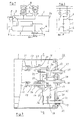
- FIG. 1 and Fig. 2 are respectively a - schematic cross-section and a skeleton diagram of a three-phase gas-insulated switch using conventional earthing switches.
- Earthing switches 3 and 4 are provided on the opposite sides of a circuit breaker 2 in a vessel 1 filled with an insulating gas at a predetermined pressure, more particularly sulphur hexafluoride SF6.
- the earthing switches 3 and 4 are respectively operated by individual actuators 5 and 6 linked with each other.
- the reference numerals 7, 8 and 9 designate disconnecting switches, busbar pipes, and insulating spacers respectively.
- the output of the circuit breaker 2 is connected to cable heads 50. Since the two earthing switches 3 and 4 are provided separately from each other, it is necessary to provide separate attaching portions, and two operating mechanisms, which increase the structure of the vessel 1.
- An object of the present invention is to reduce the space of a metal-clad vessel including a pair of earthing switches on the opposite sides of a circuit breaker.
- Another object of the present invention is to provide an improved compact earthing switch system having a common operating mechanism.
- An earthing switch for a gas-insulated switchgear apparatus includes two earthing switches which are located side by side in a common vessel filled up with an insulating gas at a predetermined pressure, and which comprise two stationary contacts cooperating with two corresponding movable contacts attached to a driving plate causing to perform opening and closing operations at the same time by a common operating mechanism.
- Each pole of the earthing switch assembly includes a first and a second stationary contact cooperating respectively with a first and a second movable rectilinear contact extending in a longitudinal parallel direction between an open position and a closed position, said first stationary contact being electrically connected to one terminal of the circuit breaker, said second stationary contact being electrically connected to the opposite terminal of the circuit breaker.
- a common driving plate made of insulating material is attached inside said vessel to said first and second movable contacts of the three poles, said plate being perpendicular to the longitudinal direction of said movable contacts.
- An operating mechanism includes a single operating shaft extending through a tight bearing of the vessel, and having an outer end which may be actuated from outside, and an inner end connected by a cinematic transmission lever to said driving plate so as to perform opening/closing operations of the two earthing switches at the same time.
- the earthing switch assembly 10 comprises two earthing switches having two sets of three-phase fixed contacts 11 and 12 and two sets of corresponding three-phase movable contacts 13 and 14 provided in a metallic vessel 1 filled with an insulating gas at a predetermined pressure, more particularly sulphur hexafluoride SF6.
- the movable contacts 13 and 14 are attached at their one end portions onto a common driving plate 15 made of an insulating material, and connected to an operating rotative shaft 19 through an operating lever 16, a link 17, and a transmission lever 18.
- the operating shaft 19 is driven by an externally provided common actuator (not shown) and led into the vessel through a bearing 22 having a seal structure provided with a step 20 and a sealing member 21.
- Sliding contacts 23 and 2 4 cooperate with the movable rectilinear contacts 13 and 14, and are fixed to a common attaching plate 25 made of an insulating material.
- the sliding contacts 23 and 24 are connected through connecting conductors 31 and 32 to a first set of stationary conductors 29 and a second set of stationary conductors 30, respectively extending through insulating bushings 27 and 28 attached onto a covering plate 26 of the vessel 1.
- the sliding contacts 23 and 2 4 which are fixed to the common attaching plate 25 are firmly held by the respective bushing conductors 29 and 30 and are electrically connected to the conductors 29 and 30 through the connecting conductors 31 and 32.
- a guiding rod 33 fixed to the covering plate 26 extends inside the vessel 1 in a parallel direction to the conductors 29, 30 and cooperates with the driving plate 15 which is driven by the operating lever 16.
- a plurality of holes 34 and notch portions 35 are provided in the driving plate 15 for the passage of the conductors 29 and 30.
- a supporting bracket 36 is attached onto the covering plate 26 for supporting a shaft 37 of the operating lever 16 and an end portion of the operating rotative shaft 19.
- the movable contacts 13 and 14 of the two earthing switches of the switch assembly 1 0 are driven by the single operating rotative shaft 19 so as to be put in their opened/closed states at the same time.
- the earthing switch assembly 10 described in the foregoing embodiment can also be used as disconnecting switches 42 provided on the opposite sides of a bus bar connecting circuit breaker 40 or a bus bar sectioning circuit breaker 41 for bus bars 38 and 39, as shown in Fig. 7.
- the driving plate 15 is then connected to the operating lever 16 through an insulating operation rod (not shown).
Landscapes
- Engineering & Computer Science (AREA)
- Power Engineering (AREA)
- Gas-Insulated Switchgears (AREA)
Priority Applications (1)
| Application Number | Priority Date | Filing Date | Title |
|---|---|---|---|
| AT86400323T ATE75352T1 (de) | 1985-02-22 | 1986-02-17 | Gasisoliertes gekapseltes schaltgeraet. |
Applications Claiming Priority (2)
| Application Number | Priority Date | Filing Date | Title |
|---|---|---|---|
| JP24272/85U | 1985-02-22 | ||
| JP1985024272U JPS61141733U (fr) | 1985-02-22 | 1985-02-22 |
Publications (3)
| Publication Number | Publication Date |
|---|---|
| EP0196240A2 true EP0196240A2 (fr) | 1986-10-01 |
| EP0196240A3 EP0196240A3 (en) | 1988-05-18 |
| EP0196240B1 EP0196240B1 (fr) | 1992-04-22 |
Family
ID=12133574
Family Applications (1)
| Application Number | Title | Priority Date | Filing Date |
|---|---|---|---|
| EP86400323A Expired - Lifetime EP0196240B1 (fr) | 1985-02-22 | 1986-02-17 | Appareil de commutation blindé à isolation gazeuse |
Country Status (4)
| Country | Link |
|---|---|
| EP (1) | EP0196240B1 (fr) |
| JP (1) | JPS61141733U (fr) |
| AT (1) | ATE75352T1 (fr) |
| DE (1) | DE3684949D1 (fr) |
Cited By (6)
| Publication number | Priority date | Publication date | Assignee | Title |
|---|---|---|---|---|
| DE3834945A1 (de) * | 1987-10-26 | 1989-05-03 | Mitsubishi Electric Corp | Gasgefuellte schaltanlage |
| CN1035853C (zh) * | 1988-01-11 | 1997-09-10 | 株式会社日立制作所 | 气体绝缘开关装置 |
| WO2001022547A1 (fr) * | 1999-09-17 | 2001-03-29 | Abb Service S.R.L. | Dispositif de commutation avec unite de mise a la terre |
| US7122758B2 (en) * | 2004-02-27 | 2006-10-17 | Abb Technology Ag | Insulated earthing switch for gas-insulated switchgear assemblies |
| WO2011135034A1 (fr) | 2010-04-28 | 2011-11-03 | Alstom Grid Ag | Sectionneur de terre a encombrement reduit |
| US11063410B2 (en) * | 2017-06-23 | 2021-07-13 | Mitsubishi Electric Corporation | Switchgear |
Family Cites Families (3)
| Publication number | Priority date | Publication date | Assignee | Title |
|---|---|---|---|---|
| GB819348A (en) * | 1955-05-24 | 1959-09-02 | Vickers Electrical Co Ltd | Improvements in and relating to electrical switchgear |
| FR2098470A5 (fr) * | 1969-12-09 | 1972-03-10 | Coq France | |
| DE2817417A1 (de) * | 1978-04-18 | 1979-10-25 | Krone Gmbh | Gas- oder fluessigkeitsisolierte mittelspannungs-schaltanlage, insbesondere fuer spannungen von 1 bis 36 kv |
-
1985
- 1985-02-22 JP JP1985024272U patent/JPS61141733U/ja active Pending
-
1986
- 1986-02-17 EP EP86400323A patent/EP0196240B1/fr not_active Expired - Lifetime
- 1986-02-17 DE DE8686400323T patent/DE3684949D1/de not_active Expired - Fee Related
- 1986-02-17 AT AT86400323T patent/ATE75352T1/de not_active IP Right Cessation
Cited By (6)
| Publication number | Priority date | Publication date | Assignee | Title |
|---|---|---|---|---|
| DE3834945A1 (de) * | 1987-10-26 | 1989-05-03 | Mitsubishi Electric Corp | Gasgefuellte schaltanlage |
| CN1035853C (zh) * | 1988-01-11 | 1997-09-10 | 株式会社日立制作所 | 气体绝缘开关装置 |
| WO2001022547A1 (fr) * | 1999-09-17 | 2001-03-29 | Abb Service S.R.L. | Dispositif de commutation avec unite de mise a la terre |
| US7122758B2 (en) * | 2004-02-27 | 2006-10-17 | Abb Technology Ag | Insulated earthing switch for gas-insulated switchgear assemblies |
| WO2011135034A1 (fr) | 2010-04-28 | 2011-11-03 | Alstom Grid Ag | Sectionneur de terre a encombrement reduit |
| US11063410B2 (en) * | 2017-06-23 | 2021-07-13 | Mitsubishi Electric Corporation | Switchgear |
Also Published As
| Publication number | Publication date |
|---|---|
| JPS61141733U (fr) | 1986-09-02 |
| EP0196240A3 (en) | 1988-05-18 |
| DE3684949D1 (de) | 1992-05-27 |
| EP0196240B1 (fr) | 1992-04-22 |
| ATE75352T1 (de) | 1992-05-15 |
Similar Documents
| Publication | Publication Date | Title |
|---|---|---|
| US7391605B2 (en) | Encapsulated gas-insulated switchgear assembly | |
| KR940004370B1 (ko) | 축소형 가스절연 개폐장치 | |
| CN1237679C (zh) | 一种气体绝缘开关装置 | |
| EP1054493B1 (fr) | Installation de commutation isolée par gaz | |
| US4215256A (en) | Gas-insulated switchgear apparatus | |
| RU2098902C1 (ru) | Газоизолированное распределительное устройство с многополюсным вакуумным выключателем и многополюсным разъединителем нагрузки | |
| KR100516854B1 (ko) | 가스절연개폐장치 | |
| US4774628A (en) | Metalclad substation subdivided into tight compartments | |
| CN1004849B (zh) | 气体绝缘开关装置 | |
| JP3612201B2 (ja) | 断路器付真空遮断器 | |
| US4211902A (en) | Apparatus for phase switching in pumping-up power station | |
| KR0144669B1 (ko) | 가스절연 개폐장치 | |
| EP0152611B1 (fr) | Appareillage de commutation blindé métallique à gaz isolant | |
| EP0196240B1 (fr) | Appareil de commutation blindé à isolation gazeuse | |
| US7378759B2 (en) | Disconnecting switch assembly | |
| SE440573B (sv) | Kapslat stellverk | |
| CN1174533C (zh) | 具有用于安置断路器的分隔式金属壳的电开关 | |
| EP4456106A1 (fr) | Appareillage de commutation | |
| US7485807B2 (en) | Gas-insulated bus bar component comprising outdoor bushings | |
| US3751617A (en) | Vacuum type circuit breaker | |
| US4736079A (en) | Puffer type electrical circuit breaker having a high dielectric withstand | |
| JPH0479708A (ja) | 開閉装置 | |
| KR100252459B1 (ko) | 가스절연 개폐장치 | |
| US20240313512A1 (en) | Switchgear architecture | |
| KR20090080961A (ko) | 전기 고전압 스위칭 스테이션 |
Legal Events
| Date | Code | Title | Description |
|---|---|---|---|
| PUAI | Public reference made under article 153(3) epc to a published international application that has entered the european phase |
Free format text: ORIGINAL CODE: 0009012 |
|
| AK | Designated contracting states |
Kind code of ref document: A2 Designated state(s): AT BE CH DE FR GB IT LI NL SE |
|
| 17P | Request for examination filed |
Effective date: 19870309 |
|
| PUAL | Search report despatched |
Free format text: ORIGINAL CODE: 0009013 |
|
| AK | Designated contracting states |
Kind code of ref document: A3 Designated state(s): AT BE CH DE FR GB IT LI NL SE |
|
| 17Q | First examination report despatched |
Effective date: 19900517 |
|
| GRAA | (expected) grant |
Free format text: ORIGINAL CODE: 0009210 |
|
| AK | Designated contracting states |
Kind code of ref document: B1 Designated state(s): AT BE CH DE FR GB IT LI NL SE |
|
| PG25 | Lapsed in a contracting state [announced via postgrant information from national office to epo] |
Ref country code: LI Effective date: 19920422 Ref country code: CH Effective date: 19920422 Ref country code: BE Effective date: 19920422 |
|
| REF | Corresponds to: |
Ref document number: 75352 Country of ref document: AT Date of ref document: 19920515 Kind code of ref document: T |
|
| REF | Corresponds to: |
Ref document number: 3684949 Country of ref document: DE Date of ref document: 19920527 |
|
| ITF | It: translation for a ep patent filed | ||
| ET | Fr: translation filed | ||
| REG | Reference to a national code |
Ref country code: CH Ref legal event code: PL |
|
| PLBE | No opposition filed within time limit |
Free format text: ORIGINAL CODE: 0009261 |
|
| STAA | Information on the status of an ep patent application or granted ep patent |
Free format text: STATUS: NO OPPOSITION FILED WITHIN TIME LIMIT |
|
| 26N | No opposition filed | ||
| EAL | Se: european patent in force in sweden |
Ref document number: 86400323.1 |
|
| PGFP | Annual fee paid to national office [announced via postgrant information from national office to epo] |
Ref country code: SE Payment date: 19990204 Year of fee payment: 14 |
|
| PGFP | Annual fee paid to national office [announced via postgrant information from national office to epo] |
Ref country code: AT Payment date: 19990211 Year of fee payment: 14 |
|
| PGFP | Annual fee paid to national office [announced via postgrant information from national office to epo] |
Ref country code: GB Payment date: 19990218 Year of fee payment: 14 |
|
| PGFP | Annual fee paid to national office [announced via postgrant information from national office to epo] |
Ref country code: FR Payment date: 20000204 Year of fee payment: 15 |
|
| PG25 | Lapsed in a contracting state [announced via postgrant information from national office to epo] |
Ref country code: GB Free format text: LAPSE BECAUSE OF NON-PAYMENT OF DUE FEES Effective date: 20000217 Ref country code: AT Free format text: LAPSE BECAUSE OF NON-PAYMENT OF DUE FEES Effective date: 20000217 |
|
| PG25 | Lapsed in a contracting state [announced via postgrant information from national office to epo] |
Ref country code: SE Free format text: LAPSE BECAUSE OF NON-PAYMENT OF DUE FEES Effective date: 20000218 |
|
| PGFP | Annual fee paid to national office [announced via postgrant information from national office to epo] |
Ref country code: DE Payment date: 20000225 Year of fee payment: 15 |
|
| PGFP | Annual fee paid to national office [announced via postgrant information from national office to epo] |
Ref country code: NL Payment date: 20000228 Year of fee payment: 15 |
|
| GBPC | Gb: european patent ceased through non-payment of renewal fee |
Effective date: 20000217 |
|
| EUG | Se: european patent has lapsed |
Ref document number: 86400323.1 |
|
| PG25 | Lapsed in a contracting state [announced via postgrant information from national office to epo] |
Ref country code: NL Free format text: LAPSE BECAUSE OF NON-PAYMENT OF DUE FEES Effective date: 20010901 |
|
| PG25 | Lapsed in a contracting state [announced via postgrant information from national office to epo] |
Ref country code: FR Free format text: LAPSE BECAUSE OF NON-PAYMENT OF DUE FEES Effective date: 20011031 |
|
| NLV4 | Nl: lapsed or anulled due to non-payment of the annual fee |
Effective date: 20010901 |
|
| REG | Reference to a national code |
Ref country code: FR Ref legal event code: ST |
|
| PG25 | Lapsed in a contracting state [announced via postgrant information from national office to epo] |
Ref country code: DE Free format text: LAPSE BECAUSE OF NON-PAYMENT OF DUE FEES Effective date: 20011201 |
|
| PG25 | Lapsed in a contracting state [announced via postgrant information from national office to epo] |
Ref country code: IT Free format text: LAPSE BECAUSE OF NON-PAYMENT OF DUE FEES;WARNING: LAPSES OF ITALIAN PATENTS WITH EFFECTIVE DATE BEFORE 2007 MAY HAVE OCCURRED AT ANY TIME BEFORE 2007. THE CORRECT EFFECTIVE DATE MAY BE DIFFERENT FROM THE ONE RECORDED. Effective date: 20050217 |