EP0196406A1 - Procédé pour la fabrication de tôles de noyau en forme de U - Google Patents
Procédé pour la fabrication de tôles de noyau en forme de U Download PDFInfo
- Publication number
- EP0196406A1 EP0196406A1 EP19860100622 EP86100622A EP0196406A1 EP 0196406 A1 EP0196406 A1 EP 0196406A1 EP 19860100622 EP19860100622 EP 19860100622 EP 86100622 A EP86100622 A EP 86100622A EP 0196406 A1 EP0196406 A1 EP 0196406A1
- Authority
- EP
- European Patent Office
- Prior art keywords
- legs
- shaped
- shaped core
- core sheets
- sheets
- Prior art date
- Legal status (The legal status is an assumption and is not a legal conclusion. Google has not performed a legal analysis and makes no representation as to the accuracy of the status listed.)
- Granted
Links
- 238000000034 method Methods 0.000 title claims abstract description 15
- 238000004519 manufacturing process Methods 0.000 title claims abstract description 8
- 238000004080 punching Methods 0.000 description 10
- 239000002184 metal Substances 0.000 description 7
- 239000002699 waste material Substances 0.000 description 7
- 238000005520 cutting process Methods 0.000 description 1
- 230000004907 flux Effects 0.000 description 1
- 230000001771 impaired effect Effects 0.000 description 1
- 239000000463 material Substances 0.000 description 1
- 238000004806 packaging method and process Methods 0.000 description 1
- 230000036316 preload Effects 0.000 description 1
- 230000009467 reduction Effects 0.000 description 1
- 230000003313 weakening effect Effects 0.000 description 1
Images

Classifications
-
- H—ELECTRICITY
- H01—ELECTRIC ELEMENTS
- H01F—MAGNETS; INDUCTANCES; TRANSFORMERS; SELECTION OF MATERIALS FOR THEIR MAGNETIC PROPERTIES
- H01F41/00—Apparatus or processes specially adapted for manufacturing or assembling magnets, inductances or transformers; Apparatus or processes specially adapted for manufacturing materials characterised by their magnetic properties
- H01F41/02—Apparatus or processes specially adapted for manufacturing or assembling magnets, inductances or transformers; Apparatus or processes specially adapted for manufacturing materials characterised by their magnetic properties for manufacturing cores, coils, or magnets
- H01F41/0206—Manufacturing of magnetic cores by mechanical means
- H01F41/0233—Manufacturing of magnetic circuits made from sheets
-
- H—ELECTRICITY
- H01—ELECTRIC ELEMENTS
- H01F—MAGNETS; INDUCTANCES; TRANSFORMERS; SELECTION OF MATERIALS FOR THEIR MAGNETIC PROPERTIES
- H01F27/00—Details of transformers or inductances, in general
- H01F27/24—Magnetic cores
- H01F27/245—Magnetic cores made from sheets, e.g. grain-oriented
-
- Y—GENERAL TAGGING OF NEW TECHNOLOGICAL DEVELOPMENTS; GENERAL TAGGING OF CROSS-SECTIONAL TECHNOLOGIES SPANNING OVER SEVERAL SECTIONS OF THE IPC; TECHNICAL SUBJECTS COVERED BY FORMER USPC CROSS-REFERENCE ART COLLECTIONS [XRACs] AND DIGESTS
- Y10—TECHNICAL SUBJECTS COVERED BY FORMER USPC
- Y10T—TECHNICAL SUBJECTS COVERED BY FORMER US CLASSIFICATION
- Y10T29/00—Metal working
- Y10T29/49—Method of mechanical manufacture
- Y10T29/49002—Electrical device making
- Y10T29/4902—Electromagnet, transformer or inductor
- Y10T29/49075—Electromagnet, transformer or inductor including permanent magnet or core
- Y10T29/49078—Laminated
-
- Y—GENERAL TAGGING OF NEW TECHNOLOGICAL DEVELOPMENTS; GENERAL TAGGING OF CROSS-SECTIONAL TECHNOLOGIES SPANNING OVER SEVERAL SECTIONS OF THE IPC; TECHNICAL SUBJECTS COVERED BY FORMER USPC CROSS-REFERENCE ART COLLECTIONS [XRACs] AND DIGESTS
- Y10—TECHNICAL SUBJECTS COVERED BY FORMER USPC
- Y10T—TECHNICAL SUBJECTS COVERED BY FORMER US CLASSIFICATION
- Y10T29/00—Metal working
- Y10T29/49—Method of mechanical manufacture
- Y10T29/49789—Obtaining plural product pieces from unitary workpiece
- Y10T29/49794—Dividing on common outline
-
- Y—GENERAL TAGGING OF NEW TECHNOLOGICAL DEVELOPMENTS; GENERAL TAGGING OF CROSS-SECTIONAL TECHNOLOGIES SPANNING OVER SEVERAL SECTIONS OF THE IPC; TECHNICAL SUBJECTS COVERED BY FORMER USPC CROSS-REFERENCE ART COLLECTIONS [XRACs] AND DIGESTS
- Y10—TECHNICAL SUBJECTS COVERED BY FORMER USPC
- Y10T—TECHNICAL SUBJECTS COVERED BY FORMER US CLASSIFICATION
- Y10T83/00—Cutting
- Y10T83/04—Processes
- Y10T83/0491—Cutting of interdigitating products
Definitions
- the invention relates to a method for producing U-shaped core sheets and between their legs matching T-shaped yoke sheets of a choke or a transformer, in particular for use as a series choke.
- recesses possibly being formed on the outer legs of the U-shaped core sheets the two mutually offset rows of U-shaped core sheets are punched out with the open sides opposite one another and with the outer legs in pairs, so that one pair of outer legs of the one row connects laterally to one pair of outer legs of the other row and from between the end faces of the outer leg pairs and the free spaces resulting from these spaced-apart middle legs of the U-shaped core sheets, the T-shaped backing sheets are punched out with transverse legs adjoining the middle legs of the U-shaped core sheets en.
- T-shaped return plates As ballasts for gas discharge lamps, chokes or transformers with U-shaped core plates and with their transverse legs inserted between their outer legs, T-shaped return plates are known (AT-PS 29 42 70). They have the advantage that the U-shaped core sheets enclosing the T-shaped return plate result in a mechanically stable structure, the parts of which on the abutting leg regions can be secured by interlocking interlocking locking devices and / or can be pressed against one another with pretensioning, as a result of which the required freedom from hum can be guaranteed with relatively simple means.
- the basic disadvantage of this U / T punch cut of the core sheets is that there is a considerable amount of punching waste during punching. Various processes for the production of such core sheets have therefore already been specified, which serve the purpose of reducing the punching waste. However, other more or less major disadvantages all had to be accepted.
- FR-PS 2070 783 a method has become known (FR-PS 2070 783) from which the invention is based and which permits the waste-free punching of U-shaped core sheets and T-shaped yoke sheets in one tool.
- the T-shaped backing plates are punched out of the free spaces laterally delimited by the outer legs of the U-shaped backing plates in such a way that the outer legs of a U-shaped core plate each laterally delimit a T-shaped backing plate lying between them with its cross leg.
- This yoke plate is in turn punched out of the two outer legs of two opposite U-shaped core sheets protruding between the outer legs of a U-shaped core sheet, with the result that corresponding recesses are necessarily formed on these outer legs of the middle leg of the T-shaped yoke sheet.
- the magnetic flux available material cross-section of the outer legs of the U-shaped core sheets reduced.
- the width and the length of the middle legs of the T-shaped yoke plates are therefore limited.
- no triangular cross-sectional recesses can be provided on the outside of the outer legs of the U-shaped core sheets, as are required for clamping an approximately U-shaped clamping rail, which ensures the necessary pretension at the cutting planes of the abutting core parts of the throttle.
- the object of the invention is therefore to provide a method for punch-free production of U-shaped core sheets and matching T-shaped backing sheets between the legs, which can be carried out with a punching tool and no restrictions with regard to the electromagnetic conditions of the choke or the transformer approximately in this means that undesirable reductions in cross-section of the magnetic path or compromises with regard to the length or the dimensions of the magnetically active core parts must be accepted.
- T-shaped yoke plates with their longitudinal leg on one side on an outer leg pair of the opposite row of U-shaped core sheets and on the other side on the longitudinal leg of an adjacent opposite T-shaped yoke plate are punched out laterally.
- profiled recesses which, for example, have an essentially triangular cross-sectional shape, can be punched out to accommodate a clamping rail that clasps the outer legs. This affects the cross-section of other core sheet metal parts Recesses not conditional; the shape of the recesses can be chosen appropriately for any purpose.
- the cross legs of the T-shaped yoke plates are punched out with a length which is somewhat greater than the distance between the parallel inner sides of the U-shaped core plates. In this way, when installing the throttle when inserting the T-shaped yoke part, the outer legs of the U-shaped core part are pressed slightly outwards, with the result that the whole structure is pre-stressed and a higher stability can thus be achieved.
- the arrangement can be made for this purpose in such a way that the T-shaped yoke plates are each formed on the end faces of their transverse legs with stamped extensions, the end face distance of which is somewhat larger than the distance between the parallel inner sides of the outer legs of the U-shaped core sheets and their Height is smaller than the height of the cross legs corresponding in their length otherwise at a distance from the inner sides of the outer legs.
- the transverse legs of the T-shaped yoke plates can also be punched out on the end faces at an angle to the center leg, so that when the T-shaped yoke part is pressed into the U-shaped core part, a pretension can also be generated at the connection points.
- the jacket core of a choke or a transformer shown in FIG. 1 is layered from U-shaped core sheets 1 and T-shaped yoke sheets 2.
- Each U-shaped core sheet 1 has two parallel, straight-sided outer legs 3 and a central leg 4 which extends at right angles and connects the two outer legs 3 to one another.
- the T-shaped yoke plates 2 are pressed with their transverse leg 5, from which a longitudinal leg 6 extends at right angles.
- An air gap 7, which may contain a deformable air gap insert, can be formed on the end face of the longitudinal legs 6.
- the U-shaped core sheets 1 and the T-shaped yoke sheets 2 are punched out of a sheet metal strip of width 8 in the manner shown in FIG. 2 by a follow-on tool.
- the arrangement is such that two rows of 9, 10 U-shaped core sheets 1 face each other with their open sides and interlock with outer legs 3, which adjoin each other in pairs.
- the adjoining U-shaped core sheets 1 of the two rows 9, 10 are offset from one another in the longitudinal direction of the tape to such an extent that an outer pair of legs 3.3 of the one row laterally adjoins the inside of an outer leg pair 3.3 of the U-shaped core sheets 1 of the other row.
- All U-shaped core sheets 1 and all T- shaped yoke plates 2 have the same size and the same dimensions.
- the T-shaped yoke plates 2 are punched out of the free spaces which arise between the end faces 11 of the outer leg pairs 3, 3 and the middle legs 4 of the U-shaped core sheets 1 which are at a distance from them.
- the T-shaped yoke plates 2 connect with their transverse legs 5 to the middle legs 4 of the U-shaped core plates, the length of a transverse leg 5 corresponding to the distance between the parallel inner sides of the outer legs 3 of a U-shaped core plate 1.
- the T-shaped yoke plates 2 close with their longitudinal leg 6 on one side to an outer leg pair 3.3 of the opposite row of U-shaped core sheets 1 and on the other side to the longitudinal leg 6 of an adjacent, opposite T-shaped yoke plate 2 laterally at.
- the punching lines shown in FIG. 2 between the individual U-shaped core sheets 1 and the T-shaped backing sheets 2 show that all sheets are punched out of the sheet metal strip in the longitudinal direction without waste.
- the outer legs 3 of the U-shaped core sheets 1 can be chosen as wide as the height of the UT plates 1, 2, ie the Eau cramp can be adapted to the respective requirements by appropriate choice of the bandwidth without any restrictions.
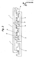
- the arrangement according to FIG. 3 corresponds essentially to that according to FIG. 2.
- Only on the outer legs 3 of the U-shaped core sheets 1 are externally profiled recesses 12 punched out, which are used to attach a U-shaped clamping rail that compresses the outer legs 3 in the finished throttle serve.
- the longitudinal legs 6 of the T-shaped yoke plates 2 are shortened at 13 by a waste web which remains in between, with which throttles with an air gap 7 according to FIG. 1 can be produced.
- the T-shaped yoke plates 2 In order to be able to press in the T-shaped yoke plates 2 with preload between the outer legs 3 of the U-shaped core plates 1, these can easily be punched out with a somewhat greater length than the distance between the inner sides of the outer legs 3 of a U-shaped one Core sheet 1 corresponds.
- the cross leg 5 of the T-shaped yoke sheets 2 can also have a small, to the middle leg 6 beveling 15 (FIG.
- the strip-shaped punching pattern shown in FIG. 2 can correspond directly to the width of the sheet metal strip from which it is punched out.
Landscapes
- Engineering & Computer Science (AREA)
- Power Engineering (AREA)
- Manufacturing & Machinery (AREA)
- Manufacturing Cores, Coils, And Magnets (AREA)
- Moulds, Cores, Or Mandrels (AREA)
- Coating With Molten Metal (AREA)
- Structures Of Non-Positive Displacement Pumps (AREA)
- Bending Of Plates, Rods, And Pipes (AREA)
- Arrangement Of Elements, Cooling, Sealing, Or The Like Of Lighting Devices (AREA)
- Coils Or Transformers For Communication (AREA)
- Manufacture Of Iron (AREA)
- Insulating Of Coils (AREA)
- Moulds For Moulding Plastics Or The Like (AREA)
Priority Applications (1)
| Application Number | Priority Date | Filing Date | Title |
|---|---|---|---|
| AT86100622T ATE41555T1 (de) | 1985-03-26 | 1986-01-18 | Verfahren zur herstellung u-foermiger kernbleche. |
Applications Claiming Priority (2)
| Application Number | Priority Date | Filing Date | Title |
|---|---|---|---|
| DE19853510854 DE3510854A1 (de) | 1985-03-26 | 1985-03-26 | Verfahren zur herstellung u-foermiger kernbleche und zwischen deren schenkel passender t-foermiger rueckschlussbleche einer drossel oder eines transformators, insbesondere fuer gasentladungslampen |
| DE3510854 | 1985-03-26 |
Publications (2)
| Publication Number | Publication Date |
|---|---|
| EP0196406A1 true EP0196406A1 (fr) | 1986-10-08 |
| EP0196406B1 EP0196406B1 (fr) | 1989-03-15 |
Family
ID=6266322
Family Applications (1)
| Application Number | Title | Priority Date | Filing Date |
|---|---|---|---|
| EP19860100622 Expired EP0196406B1 (fr) | 1985-03-26 | 1986-01-18 | Procédé pour la fabrication de tôles de noyau en forme de U |
Country Status (15)
| Country | Link |
|---|---|
| US (1) | US4711019A (fr) |
| EP (1) | EP0196406B1 (fr) |
| CN (1) | CN86102094A (fr) |
| AT (1) | ATE41555T1 (fr) |
| AU (1) | AU585960B2 (fr) |
| BG (1) | BG60613B2 (fr) |
| DD (1) | DD244231A5 (fr) |
| DE (2) | DE3510854A1 (fr) |
| FI (1) | FI80965C (fr) |
| GR (1) | GR860166B (fr) |
| HU (1) | HU193402B (fr) |
| PL (1) | PL148377B1 (fr) |
| SU (1) | SU1450764A3 (fr) |
| UA (1) | UA7588A1 (fr) |
| YU (1) | YU46521B (fr) |
Cited By (3)
| Publication number | Priority date | Publication date | Assignee | Title |
|---|---|---|---|---|
| EP0671750A1 (fr) * | 1994-03-08 | 1995-09-13 | TRANCERIA LIGURE S.r.l. | Procédé de fabrication de noyaux pour transformateurs |
| EP1852892A4 (fr) * | 2004-12-22 | 2009-01-07 | Jin Li | Generateur d'energie magnetique et lampe a energie magnetique combines de type traversant |
| EP2927918A3 (fr) * | 2014-04-03 | 2015-10-21 | SUMIDA Components & Modules GmbH | Inductance et noyau inducteur |
Families Citing this family (19)
| Publication number | Priority date | Publication date | Assignee | Title |
|---|---|---|---|---|
| US4897916A (en) * | 1988-08-29 | 1990-02-06 | Coils, Inc. | Method for making a tranformer core assembly |
| JPH0289304A (ja) * | 1988-09-27 | 1990-03-29 | Kitamura Kiden Kk | 巻鉄心用帯材の切抜方法 |
| US5188305A (en) * | 1988-09-27 | 1993-02-23 | Kitamura Kiden Co., Ltd. | Apparatus for cutting winding strips for use in a wound core |
| US5373625A (en) * | 1991-10-15 | 1994-12-20 | Rohm Co., Ltd. | Method for making thermal heads |
| DE4139003A1 (de) * | 1991-11-27 | 1993-06-03 | May & Christe Gmbh | Magnetkern in mantelbauweise einer drossel oder eines transformators, geschichtet aus c- und i-foermigen kernblechen |
| JP2901413B2 (ja) * | 1992-04-22 | 1999-06-07 | 北村機電株式会社 | 巻鉄心用帯材の切り抜き装置 |
| ES2110357B1 (es) * | 1995-05-05 | 1998-10-01 | Luminotecnicas Especial | Procedimiento de fabricacion de nucleos magneticos para reactancias y transformadores. |
| IT1286752B1 (it) * | 1996-11-08 | 1998-07-17 | Omnitex Srl | Procedimento di taglio di un materasso di strati di tessuto per agevolare il prelievo di pacchetti di pezzi tagliati e macchina per |
| ES2157832B1 (es) * | 1999-09-24 | 2002-02-16 | Ventura Ind | Procedimiento para el troquelado de chapas constitutivas de nucleos magneticos. |
| ES2155806B1 (es) * | 1999-10-07 | 2001-10-16 | Ventura Ind | Procedimiento de troquelado de chapas constitutivas de nucleos magneticos en forma de "e" y de "t". |
| US6975049B2 (en) * | 2003-10-29 | 2005-12-13 | A. O. Smith Corporation | Electrical machine and method of manufacturing the same |
| TW200618003A (en) * | 2004-11-26 | 2006-06-01 | Mu-Tu Li | Electric device, and its labor and materials |
| CN100447939C (zh) * | 2004-12-22 | 2008-12-31 | 李进 | 外包组合式磁能发生器及其磁能灯 |
| US7646281B2 (en) * | 2005-01-14 | 2010-01-12 | Lincoln Global, Inc. | Snap-together choke and transformer assembly for an electric arc welder |
| CN101284294B (zh) * | 2007-04-10 | 2010-04-21 | 上海电气集团上海电机厂有限公司 | 一种硅钢片冲压模具刃块的加工工艺 |
| JP5271407B2 (ja) * | 2008-04-01 | 2013-08-21 | エン,シアン コー | 多重コイル蛍光灯バラスト |
| WO2017111249A1 (fr) * | 2015-12-22 | 2017-06-29 | 주식회사 포스코티엠씨 | Appareil de fabrication de noyau laminé adhésif |
| CN105798103B (zh) * | 2016-05-09 | 2019-02-01 | 顺德工业(江苏)有限公司 | 一种电磁阀式间歇剪断装置 |
| CN108766756B (zh) * | 2018-08-02 | 2024-03-29 | 青岛云路先进材料技术股份有限公司 | 铁芯的卷绕芯模 |
Citations (5)
| Publication number | Priority date | Publication date | Assignee | Title |
|---|---|---|---|---|
| FR2070783A1 (fr) * | 1969-12-09 | 1971-09-17 | Zumtobel Walter | |
| DE2638780A1 (de) * | 1975-09-03 | 1977-03-17 | Leuenberger H | Mantelfoermiger magnetkern fuer einen transformator oder eine induktionsspule |
| DE2745701A1 (de) * | 1976-10-11 | 1978-04-13 | Helvar Oy | Eisenkern fuer eine drossel oder einen wandler und verfahren zu dessen herstellung |
| DE2652171A1 (de) * | 1976-11-16 | 1978-05-24 | Bertos Ag | Vorschaltgeraet u.dgl. mit e- und i-foermigen kernblechen |
| DE2836401C2 (de) * | 1978-08-19 | 1983-09-08 | Fa. Hermann Schwabe, 7067 Urbach | Streufeldtransformator oder Drossel, insbesondere als Vorschaltgerät für Gasentladungslampen |
Family Cites Families (8)
| Publication number | Priority date | Publication date | Assignee | Title |
|---|---|---|---|---|
| US3201731A (en) * | 1962-11-27 | 1965-08-17 | Electro Netic Steel Inc | Transformer core and lamination therefor |
| US3181402A (en) * | 1963-04-03 | 1965-05-04 | David J Kuck | Method of forming f-shaped and l-shaped laminations for shell-type core |
| US3456535A (en) * | 1966-07-18 | 1969-07-22 | Allegheny Ludlum Steel | Laminations without scrap |
| US3491437A (en) * | 1968-05-06 | 1970-01-27 | Allegheny Ludlum Steel | Scrapless method of stamping e laminations |
| AT294270B (de) * | 1969-07-14 | 1971-11-10 | Berndeisel & Co Johann | Drossel für Entladungslampen, insbesondere Leuchtstofflampen |
| AT304692B (de) * | 1969-12-29 | 1973-01-25 | Zumtobel Walter | Eisenpaket oder Kern, vorzugsweise aus geschichteten Lamellen |
| AT304690B (de) * | 1970-02-05 | 1973-01-25 | Zumtobel Walter | Transformator oder Induktionsspule |
| DE2309727C3 (de) * | 1973-02-27 | 1979-05-03 | Fa. Hermann Schwabe, 7067 Urbach | Verfahren zur Herstellung von insbesondere als Vorschaltgerät für Gasentladungslampen zu verwendende Drosseln oder Transformatoren |
-
1985
- 1985-03-26 DE DE19853510854 patent/DE3510854A1/de not_active Withdrawn
-
1986
- 1986-01-18 AT AT86100622T patent/ATE41555T1/de not_active IP Right Cessation
- 1986-01-18 EP EP19860100622 patent/EP0196406B1/fr not_active Expired
- 1986-01-18 DE DE8686100622T patent/DE3662477D1/de not_active Expired
- 1986-01-21 GR GR860166A patent/GR860166B/el not_active IP Right Cessation
- 1986-02-14 UA UA4019573A patent/UA7588A1/uk unknown
- 1986-02-14 SU SU864019573A patent/SU1450764A3/ru active
- 1986-02-25 FI FI860805A patent/FI80965C/fi not_active IP Right Cessation
- 1986-03-18 US US06/840,919 patent/US4711019A/en not_active Expired - Lifetime
- 1986-03-19 BG BG074147A patent/BG60613B2/xx unknown
- 1986-03-19 PL PL1986258490A patent/PL148377B1/pl unknown
- 1986-03-19 YU YU43486A patent/YU46521B/sh unknown
- 1986-03-24 DD DD86288239A patent/DD244231A5/de unknown
- 1986-03-25 AU AU55220/86A patent/AU585960B2/en not_active Expired
- 1986-03-26 CN CN198686102094A patent/CN86102094A/zh active Pending
- 1986-03-26 HU HU861281A patent/HU193402B/hu unknown
Patent Citations (5)
| Publication number | Priority date | Publication date | Assignee | Title |
|---|---|---|---|---|
| FR2070783A1 (fr) * | 1969-12-09 | 1971-09-17 | Zumtobel Walter | |
| DE2638780A1 (de) * | 1975-09-03 | 1977-03-17 | Leuenberger H | Mantelfoermiger magnetkern fuer einen transformator oder eine induktionsspule |
| DE2745701A1 (de) * | 1976-10-11 | 1978-04-13 | Helvar Oy | Eisenkern fuer eine drossel oder einen wandler und verfahren zu dessen herstellung |
| DE2652171A1 (de) * | 1976-11-16 | 1978-05-24 | Bertos Ag | Vorschaltgeraet u.dgl. mit e- und i-foermigen kernblechen |
| DE2836401C2 (de) * | 1978-08-19 | 1983-09-08 | Fa. Hermann Schwabe, 7067 Urbach | Streufeldtransformator oder Drossel, insbesondere als Vorschaltgerät für Gasentladungslampen |
Cited By (3)
| Publication number | Priority date | Publication date | Assignee | Title |
|---|---|---|---|---|
| EP0671750A1 (fr) * | 1994-03-08 | 1995-09-13 | TRANCERIA LIGURE S.r.l. | Procédé de fabrication de noyaux pour transformateurs |
| EP1852892A4 (fr) * | 2004-12-22 | 2009-01-07 | Jin Li | Generateur d'energie magnetique et lampe a energie magnetique combines de type traversant |
| EP2927918A3 (fr) * | 2014-04-03 | 2015-10-21 | SUMIDA Components & Modules GmbH | Inductance et noyau inducteur |
Also Published As
| Publication number | Publication date |
|---|---|
| AU5522086A (en) | 1986-10-02 |
| HUT40855A (en) | 1987-02-27 |
| GR860166B (en) | 1986-05-13 |
| AU585960B2 (en) | 1989-06-29 |
| FI860805A7 (fi) | 1986-09-27 |
| DE3510854A1 (de) | 1986-10-02 |
| FI80965C (fi) | 1990-08-10 |
| UA7588A1 (uk) | 1995-09-29 |
| DE3662477D1 (en) | 1989-04-20 |
| CN86102094A (zh) | 1986-09-24 |
| DD244231A5 (de) | 1987-03-25 |
| ATE41555T1 (de) | 1989-04-15 |
| FI80965B (fi) | 1990-04-30 |
| PL148377B1 (en) | 1989-10-31 |
| US4711019A (en) | 1987-12-08 |
| BG60613B2 (en) | 1995-10-31 |
| SU1450764A3 (ru) | 1989-01-07 |
| HU193402B (en) | 1987-10-28 |
| YU43486A (en) | 1988-02-29 |
| FI860805A0 (fi) | 1986-02-25 |
| EP0196406B1 (fr) | 1989-03-15 |
| YU46521B (sh) | 1993-11-16 |
Similar Documents
| Publication | Publication Date | Title |
|---|---|---|
| EP0196406B1 (fr) | Procédé pour la fabrication de tôles de noyau en forme de U | |
| DE69523798T2 (de) | Verfahren zur Herstellung von Transformatorenkernen | |
| EP0551104A1 (fr) | Lame de scie | |
| EP0100871A1 (fr) | Procédé de production d'un paquet de tôle, notamment pour l'induit de machines et appareils électriques | |
| DE2933781C2 (de) | Verfahren zum Herstellen E-förmiger Kernbleche und I-förmiger Rückschlußbleche einer Drossel oder eines Transformators insbesondere für Gasentladungslampen | |
| DE2801074C2 (fr) | ||
| DE60311300T2 (de) | Verbindungselement für invertierte t-förmige träger | |
| DE4413880C1 (de) | Pontentialverteiler, insbesondere für Sicherungsdosen von Kraftfahrzeugen | |
| DE2541222A1 (de) | Kontaktvorrichtung | |
| DE2428076C2 (de) | Transformator oder Drossel mit mindestens einer Drahtwicklung | |
| DE3539894A1 (de) | Verkleidung fuer bauwerke | |
| DE4224473C2 (de) | Schalung für den Betonbau sowie Vorrichtung zum Herstellen der Schalung | |
| DE2650929A1 (de) | Vorschaltgeraet u.dgl. mit im wesentlichen abfallos gestanzten e- und i-foermigen kernblechen | |
| EP0580131B1 (fr) | Procédé de fabrication d'une réactance ou d'un transformateur avec des tôles de noyau en forme de E constituées de deux tôles en forme de U | |
| CH416817A (de) | Magnetkern, insbesondere für Transformatoren oder Drosseln | |
| DE2638780A1 (de) | Mantelfoermiger magnetkern fuer einen transformator oder eine induktionsspule | |
| DE19645098A1 (de) | Drossel und Verfahren zu deren Herstellung | |
| DE2652171A1 (de) | Vorschaltgeraet u.dgl. mit e- und i-foermigen kernblechen | |
| DE3318099C2 (fr) | ||
| EP0240737B1 (fr) | Bobine de ballast, plus particulièrement pour lampes à décharge | |
| DE2745701C2 (de) | Dreischenkliger Blechschichtkern und Verfahren zu dessen Herstellung | |
| DE1858058U (de) | Tragvorrichtung. | |
| DE2950727C2 (de) | Drosselspule für das Vorschaltgerät von Leuchtstofflampen | |
| DE1540731A1 (de) | Elektrisches Drahtheiz-Element | |
| DE2216346C3 (de) | Elektrisches Kontaktglied, und mit diesem ausgerüsteter Verbindungsstecker |
Legal Events
| Date | Code | Title | Description |
|---|---|---|---|
| PUAI | Public reference made under article 153(3) epc to a published international application that has entered the european phase |
Free format text: ORIGINAL CODE: 0009012 |
|
| AK | Designated contracting states |
Kind code of ref document: A1 Designated state(s): AT DE FR GB IT NL |
|
| 17P | Request for examination filed |
Effective date: 19860918 |
|
| RAP1 | Party data changed (applicant data changed or rights of an application transferred) |
Owner name: SCHWABE GMBH |
|
| 17Q | First examination report despatched |
Effective date: 19880311 |
|
| GRAA | (expected) grant |
Free format text: ORIGINAL CODE: 0009210 |
|
| AK | Designated contracting states |
Kind code of ref document: B1 Designated state(s): AT DE FR GB IT NL |
|
| REF | Corresponds to: |
Ref document number: 41555 Country of ref document: AT Date of ref document: 19890415 Kind code of ref document: T |
|
| ITF | It: translation for a ep patent filed | ||
| REF | Corresponds to: |
Ref document number: 3662477 Country of ref document: DE Date of ref document: 19890420 |
|
| ET | Fr: translation filed | ||
| GBT | Gb: translation of ep patent filed (gb section 77(6)(a)/1977) | ||
| PLBE | No opposition filed within time limit |
Free format text: ORIGINAL CODE: 0009261 |
|
| STAA | Information on the status of an ep patent application or granted ep patent |
Free format text: STATUS: NO OPPOSITION FILED WITHIN TIME LIMIT |
|
| 26N | No opposition filed | ||
| ITTA | It: last paid annual fee | ||
| REG | Reference to a national code |
Ref country code: FR Ref legal event code: TP Ref country code: FR Ref legal event code: CD Ref country code: FR Ref legal event code: CA |
|
| NLT1 | Nl: modifications of names registered in virtue of documents presented to the patent office pursuant to art. 16 a, paragraph 1 |
Owner name: SCHWABE URBACH GMBH TE URBACH, BONDSREPUBLIEK DUIT |
|
| NLS | Nl: assignments of ep-patents |
Owner name: VOSSLOH SCHWABE GMBH TE URBACH, BONDSREPUBLIEK DUI |
|
| REG | Reference to a national code |
Ref country code: GB Ref legal event code: 732E |
|
| ITPR | It: changes in ownership of a european patent |
Owner name: CESSIONE;VOSSLOH SCHWABE GMBH |
|
| REG | Reference to a national code |
Ref country code: GB Ref legal event code: IF02 |
|
| NLT1 | Nl: modifications of names registered in virtue of documents presented to the patent office pursuant to art. 16 a, paragraph 1 |
Owner name: VOSSLOH-SCHWABE DEUTSCHLAND GMBH |
|
| PGFP | Annual fee paid to national office [announced via postgrant information from national office to epo] |
Ref country code: NL Payment date: 20050110 Year of fee payment: 20 Ref country code: GB Payment date: 20050110 Year of fee payment: 20 |
|
| PGFP | Annual fee paid to national office [announced via postgrant information from national office to epo] |
Ref country code: FR Payment date: 20050111 Year of fee payment: 20 |
|
| PGFP | Annual fee paid to national office [announced via postgrant information from national office to epo] |
Ref country code: AT Payment date: 20050118 Year of fee payment: 20 |
|
| PGFP | Annual fee paid to national office [announced via postgrant information from national office to epo] |
Ref country code: IT Payment date: 20050126 Year of fee payment: 20 |
|
| PGFP | Annual fee paid to national office [announced via postgrant information from national office to epo] |
Ref country code: DE Payment date: 20050131 Year of fee payment: 20 |
|
| REG | Reference to a national code |
Ref country code: GB Ref legal event code: PE20 |
|
| REG | Reference to a national code |
Ref country code: FR Ref legal event code: CD |
|
| PG25 | Lapsed in a contracting state [announced via postgrant information from national office to epo] |
Ref country code: GB Free format text: LAPSE BECAUSE OF EXPIRATION OF PROTECTION Effective date: 20060117 |
|
| PG25 | Lapsed in a contracting state [announced via postgrant information from national office to epo] |
Ref country code: NL Free format text: LAPSE BECAUSE OF EXPIRATION OF PROTECTION Effective date: 20060118 |
|
| NLV7 | Nl: ceased due to reaching the maximum lifetime of a patent |
Effective date: 20060118 |