EP0196421A2 - Verfahren zum Regenerieren von Russfiltern bei Diesel-Brennkraftmaschinen - Google Patents
Verfahren zum Regenerieren von Russfiltern bei Diesel-Brennkraftmaschinen Download PDFInfo
- Publication number
- EP0196421A2 EP0196421A2 EP86101394A EP86101394A EP0196421A2 EP 0196421 A2 EP0196421 A2 EP 0196421A2 EP 86101394 A EP86101394 A EP 86101394A EP 86101394 A EP86101394 A EP 86101394A EP 0196421 A2 EP0196421 A2 EP 0196421A2
- Authority
- EP
- European Patent Office
- Prior art keywords
- temperature
- exhaust gas
- filter
- diesel engine
- tnf
- Prior art date
- Legal status (The legal status is an assumption and is not a legal conclusion. Google has not performed a legal analysis and makes no representation as to the accuracy of the status listed.)
- Granted
Links
Images


Classifications
-
- F—MECHANICAL ENGINEERING; LIGHTING; HEATING; WEAPONS; BLASTING
- F01—MACHINES OR ENGINES IN GENERAL; ENGINE PLANTS IN GENERAL; STEAM ENGINES
- F01N—GAS-FLOW SILENCERS OR EXHAUST APPARATUS FOR MACHINES OR ENGINES IN GENERAL; GAS-FLOW SILENCERS OR EXHAUST APPARATUS FOR INTERNAL-COMBUSTION ENGINES
- F01N9/00—Electrical control of exhaust gas treating apparatus
- F01N9/002—Electrical control of exhaust gas treating apparatus of filter regeneration
-
- F—MECHANICAL ENGINEERING; LIGHTING; HEATING; WEAPONS; BLASTING
- F01—MACHINES OR ENGINES IN GENERAL; ENGINE PLANTS IN GENERAL; STEAM ENGINES
- F01N—GAS-FLOW SILENCERS OR EXHAUST APPARATUS FOR MACHINES OR ENGINES IN GENERAL; GAS-FLOW SILENCERS OR EXHAUST APPARATUS FOR INTERNAL-COMBUSTION ENGINES
- F01N3/00—Exhaust or silencing apparatus having means for purifying, rendering innocuous, or otherwise treating exhaust
- F01N3/02—Exhaust or silencing apparatus having means for purifying, rendering innocuous, or otherwise treating exhaust for cooling, or for removing solid constituents of, exhaust
- F01N3/021—Exhaust or silencing apparatus having means for purifying, rendering innocuous, or otherwise treating exhaust for cooling, or for removing solid constituents of, exhaust by means of filters
- F01N3/023—Exhaust or silencing apparatus having means for purifying, rendering innocuous, or otherwise treating exhaust for cooling, or for removing solid constituents of, exhaust by means of filters using means for regenerating the filters, e.g. by burning trapped particles
-
- F—MECHANICAL ENGINEERING; LIGHTING; HEATING; WEAPONS; BLASTING
- F02—COMBUSTION ENGINES; HOT-GAS OR COMBUSTION-PRODUCT ENGINE PLANTS
- F02D—CONTROLLING COMBUSTION ENGINES
- F02D41/00—Electrical control of supply of combustible mixture or its constituents
- F02D41/02—Circuit arrangements for generating control signals
- F02D41/021—Introducing corrections for particular conditions exterior to the engine
- F02D41/0235—Introducing corrections for particular conditions exterior to the engine in relation with the state of the exhaust gas treating apparatus
- F02D41/027—Introducing corrections for particular conditions exterior to the engine in relation with the state of the exhaust gas treating apparatus to purge or regenerate the exhaust gas treating apparatus
- F02D41/029—Introducing corrections for particular conditions exterior to the engine in relation with the state of the exhaust gas treating apparatus to purge or regenerate the exhaust gas treating apparatus the exhaust gas treating apparatus being a particulate filter
-
- F—MECHANICAL ENGINEERING; LIGHTING; HEATING; WEAPONS; BLASTING
- F01—MACHINES OR ENGINES IN GENERAL; ENGINE PLANTS IN GENERAL; STEAM ENGINES
- F01N—GAS-FLOW SILENCERS OR EXHAUST APPARATUS FOR MACHINES OR ENGINES IN GENERAL; GAS-FLOW SILENCERS OR EXHAUST APPARATUS FOR INTERNAL-COMBUSTION ENGINES
- F01N2390/00—Arrangements for controlling or regulating exhaust apparatus
- F01N2390/02—Arrangements for controlling or regulating exhaust apparatus using electric components only
-
- F—MECHANICAL ENGINEERING; LIGHTING; HEATING; WEAPONS; BLASTING
- F01—MACHINES OR ENGINES IN GENERAL; ENGINE PLANTS IN GENERAL; STEAM ENGINES
- F01N—GAS-FLOW SILENCERS OR EXHAUST APPARATUS FOR MACHINES OR ENGINES IN GENERAL; GAS-FLOW SILENCERS OR EXHAUST APPARATUS FOR INTERNAL-COMBUSTION ENGINES
- F01N2430/00—Influencing exhaust purification, e.g. starting of catalytic reaction, filter regeneration, or the like, by controlling engine operating characteristics
- F01N2430/06—Influencing exhaust purification, e.g. starting of catalytic reaction, filter regeneration, or the like, by controlling engine operating characteristics by varying fuel-air ratio, e.g. by enriching fuel-air mixture
-
- F—MECHANICAL ENGINEERING; LIGHTING; HEATING; WEAPONS; BLASTING
- F02—COMBUSTION ENGINES; HOT-GAS OR COMBUSTION-PRODUCT ENGINE PLANTS
- F02B—INTERNAL-COMBUSTION PISTON ENGINES; COMBUSTION ENGINES IN GENERAL
- F02B3/00—Engines characterised by air compression and subsequent fuel addition
- F02B3/06—Engines characterised by air compression and subsequent fuel addition with compression ignition
-
- Y—GENERAL TAGGING OF NEW TECHNOLOGICAL DEVELOPMENTS; GENERAL TAGGING OF CROSS-SECTIONAL TECHNOLOGIES SPANNING OVER SEVERAL SECTIONS OF THE IPC; TECHNICAL SUBJECTS COVERED BY FORMER USPC CROSS-REFERENCE ART COLLECTIONS [XRACs] AND DIGESTS
- Y02—TECHNOLOGIES OR APPLICATIONS FOR MITIGATION OR ADAPTATION AGAINST CLIMATE CHANGE
- Y02T—CLIMATE CHANGE MITIGATION TECHNOLOGIES RELATED TO TRANSPORTATION
- Y02T10/00—Road transport of goods or passengers
- Y02T10/10—Internal combustion engine [ICE] based vehicles
- Y02T10/40—Engine management systems
Definitions
- the invention relates to a method for systematically burning off solid particles (soot) formed and collected from the exhaust gas flow of a diesel internal combustion engine (diesel engine) in a filter, a throttle valve provided in the intake line for the combustion air being actuated in a certain manner.
- a throttle valve in the intake air line is controlled in such a way that in certain operating states, by closing the throttle valve and the associated reduction in the air supply, the exhaust gas temperature rises, with the result that in an in The soot filter provided in the exhaust pipe reaches the ignition temperature of the soot deposited there.
- the soot filter can be completely regenerated.
- the prerequisite here is that the engine is driven in the upper part-load range during the regeneration process, which means either high speed or overcoming an incline in a vehicle drive.
- the required ignition temperature in the exhaust gas can only be achieved by means of an additional heating device.
- the throttle valve position in the known regeneration system between two end positions is controlled by a microcomputer, the input signals of which correspond to the following measured variables: accelerator pedal position, engine speed, exhaust gas temperature upstream of the soot filter, temperature inside the soot filter.
- the regeneration process can be initiated automatically or by hand.
- a variable control of the throttle valve taking into account the above-mentioned measured variables, is intended to ensure that the filter temperature does not exceed a certain maximum value to protect the soot filter and that there is always a slight excess of oxygen in the exhaust gas to suppress smoke during the burning off of the soot collected in the soot filter.
- the present invention has for its object to provide a method for cleaning soot filters in diesel engines for driving work machines such as forklifts or the like. In their normal operation, the high exhaust gas temperatures required for soot combustion are not achieved.
- the proposed solution is based on the knowledge that such machines may be operated in shifts, so that it is usually sufficient if the soot filter is cleaned after each shift and that the cleaning process can preferably take place while the machine is stationary.
- Such a method for regeneration of the soot filter is in claim 1 under para. 1 to 6 marked.
- no. 1 is measured in idle mode at a speed of 800 rpm, for example, the back pressure PVF of the loaded soot filter and with an upper limit pressure PG1, e.g. compared to 80 mbar. If this pressure is exceeded, the soot filter is loaded, i.e. Regeneration required.
- the idle conditions allow a defined starting position to be reached in a simple manner.
- a first signal is generated for PVF> PG1, whereupon the diesel engine is driven in the upper part-load range, ie close to full load, for example against the vehicle brake or the vehicle hydraulics, the hydraulic pump working against a resistance.
- the exhaust gas temperature rises until it exceeds a given first temperature value TG1.
- This comparison can be carried out either by measuring the temperature TNF after the filter, the temperature value TG used for the comparison being approximately 450 ° C., or by comparing temperature differences by determining the temperature difference from measurements before and after the soot filter TVF-TNF.
- This temperature difference which decreases at high partial load of the diesel engine with increasing exhaust gas temperature (after filter) TNF at full load of the diesel engine, is then compared with a temperature value which corresponds to a predetermined first temperature difference DT1, for example in the order of 90 ° C. If the difference between the measured exhaust gas temperatures TVF - TNV ⁇ DT1, then according to No. 4 generates a second signal as a prerequisite for now that the throttle valve is closed against a stop.
- the stop defines a specific throttle valve position with a corresponding reduction in cross-section or throughput reduction. Instead of a fixed stop, this throttle valve position (throttle valve closed) can also be variably controlled, preferably in such a way that, in the event of continued operation in the upper part-load range (e.g. full throttle at a given load), the temperature TVF upstream of the filter does not exceed a predetermined upper limit temperature to protect the soot filter .
- a temperature comparison can also be provided according to the relationship TNF - TVF ⁇ DT2; the latter is a predetermined second temperature difference, on the order of 50 ° C, for example. Only when this value is reached or undershot is the soot largely burned, ie the temperature TNF after the filter has dropped significantly and the increased air supply when dethrottling can no longer damage the soot filter.
- corresponding display devices preferably signal lamps, can be actuated, which also enable the driver to trigger the next procedural step manually. Two lights are sufficient, which are lit by the first two signals and extinguished by the third and fourth signals.
- the two-stage system control is particularly important in the method according to the invention, in the first stage a first temperature rise up to a temperature TVF upstream of a filter of e.g. 480 ° C under load with the throttle open and a second temperature rise up to a temperature TVF in front of the filter of e.g. 660 ° C - is generated by maintaining the load operation with the throttle valve closed. Without such a step control, the temperature in the soot filter would rise too quickly and too high with the risk that the soot filter would be destroyed in the process.
- the soot filter is only heated, so that the soot is burned off particularly uniformly in the second stage.
- the surprisingly low temperature peak is particularly noteworthy here - the temperature TNF after the filter only rises to e.g. 800 ° C on - while with single-stage regeneration (throttle valve closed from the start), temperature peaks of over l100 ° C are the rule. According to the method according to the invention, the soot filter is therefore protected, i.e. achieved a long service life.
- a diesel engine 1 is connected to an air filter 3 via an intake line 2.
- a throttle valve 4 which is either automatically via a control unit 5 or manually via an actuating device 6, e.g. by the driver of a work vehicle (not shown), e.g. a fork lifter, can be actuated.
- control unit 5 is connected on the input side to the various measured variables, namely a signal input 7 for the engine load, for example analogously to the accelerator pedal position, also a signal input 8 for the engine speed n, a further signal input 9 for the pressure p in the exhaust line 11 before soot filter 12 switched on therein and finally a signal input 10 for the temperature T of the exhaust gas flow upstream of the soot filter 12.
- the outputs of the control device 5 comprise a first (optional) signal line 13 to the throttle valve 4 and two further signal lines 14, 15 to the control lamps L1 and L2 .
- the throttle flap 4 in the intake line is closed either under control of the control unit 5 or via a manual actuation device 6 during the load operation of the diesel engine the driver looks at the light signals from the two warning lights Ll and L2.
- the engine is then loaded by the driver against the vehicle brake or the vehicle hydraulics and driven under high load at full throttle in order to raise the temperature in the exhaust line 11. Only when the temperature TNF measured there after the soot filter 12 exceeds a first predetermined limit value TG1 does the control lamp L2.
- the temperature comparison TNF> TG1 explained above can be replaced by a comparison of temperature differences by measuring the temperatures before and after the soot filter 12 and according to the relationship are compared with one another, where DT1 is a predetermined first temperature difference. Only when this condition is met does the warning lamp L2 light up
- TNF - TVF ⁇ DT2 where DT2 is a predetermined second temperature difference.
- TNF TNF ⁇ TG2, where TG2 is a second predetermined temperature value.
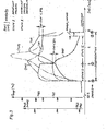
- the curve profiles TVF, TNF, PVF over the regeneration time shown in FIG. 3 clearly show the two-stage process control.
- stage I the engine is operated without throttle actuation but under high partial load; the temperature after the soot filter TNF rises to a level of about 450 ° C.
- stage II the temperature upstream of the TVF filter rises steeply, to about 650 ° C.
- the burning of the soot that has accumulated in the soot filter then takes place at this temperature level.
- the temperature after the soot filter TNF rises almost continuously and reaches a short-term maximum at around 850 ° C in the area of the second stage II (cf. dashed curve).
- the throttle valve After reaching the lower pressure limit PG2, the throttle valve is opened again and the temperature before and after the filter drops rapidly. It should be noted here that the quality of the TNF is approximately the same as the temperature (not measured) inside the soot filter. If you were to drive the engine under high partial load with the throttle closed at the beginning of stage I, the dash-dot temperature curves (TVF) and (TNF) would occur. The temperature upstream of the filter (TVF) would rise considerably faster to a level which corresponds to the ignition temperature of the soot; at the same time but the temperature in the filter, as can be seen from the curve (TNF), very quickly rise to a value above 1100 ° C, which would result in the destruction of the filter. 3 thus clearly shows the essential effect of the two-stage regeneration process, as is proposed here for work machines in which the regeneration can take place while the vehicle is stationary.
Landscapes
- Engineering & Computer Science (AREA)
- Chemical & Material Sciences (AREA)
- Combustion & Propulsion (AREA)
- Mechanical Engineering (AREA)
- General Engineering & Computer Science (AREA)
- Processes For Solid Components From Exhaust (AREA)
Abstract
Description
- Die Erfindung betrifft ein Verfahren zum systematischen Abbrennen von aus dem Abgasstrom einer Diesel-Brennkraftmaschine (Dieselmotor) in einem Filter gebildeten und gesammelten Feststoffteilchen (Ruß), wobei eine in der Ansaugleitung für die Verbrennungsluft vorgesehene Drosselklappe in bestimmter Weise betätigt wird.
- Bei einem bekannten System zum Regenerieren eines Rußfilters (EP-A1-103 84) wird eine Drosselklappe in der Ansaugluftleitung derart gesteuert, daß in bestimmten Betriebszuständen durch Schließen der Drosselklappe und damit verbundener Reduzierung der Luftzufuhr die Abgastemperatur ansteigt mit der Folge, daß in einem in der Abgasleitung vorgesehenen Rußfilter die Zündtemperatur des dort abgelagerten Rußes erreicht wird. Durch Aufrechterhaltung dieses Zustands während einiger Minuten gelingt es, das Rußfilter vollständig zu regenerieren. Voraussetzung dabei ist, daß der Motor während des Regeniervorgangs im oberen Teillastbereich gefahren wird, was bei einem Fahrzeugantrieb entweder eine hohe Geschwindigkeit oder Überwinden einer Steigung bedeutet.
- Im unteren Teillastbereich des Motors hingegen kann die erforderliche Zündtemperatur im Abgas nur mittels einer zusätzlichen Aufheizvorrichtung erreicht werden.
- Die Drosselklappenstellung wird bei dem bekannten Regenerierungssystem zwischen zwei Endstellungen gesteuert über einen Mikrocomputer, dessen Eingangssig- , nale folgenden Meßgrößen entsprechen: Gaspedalstellung, Motordrehzahl, Abgastemperatur vor dem Rußfilter, Temperatur im Inneren des Rußfilters. Der Regeneriervorgang kann dabei automatisch oder von Hand initiiert werden. Durch eine variable Steuerung der Drosseklappe unter Berücksichtigung der genannten Meßgrößen soll erreicht werden, daß zum Schutz des Rußfilters die Filtertemperatur einen bestimmten Höchstwert nicht überschreitet und daß stets ein geringer Sauerstoffüberschuß im Abgas zur Unterdrückung von Rauch während des Abbrennens des im Rußfilter angesammelten Rußes vorhanden ist.
- Es ist selbstverständlich, daß für Diesel-PKWs wegen des ständigen Wechsels der Betriebsbedingungen ein derart aufwendiges Regenerierungssystem unerläßlich ist.
- Demgegenüber liegt der vorliegenden Erfindung die Aufgabe zugrunde ein Verfahren zur Reinigung von Rußfiltern bei Dieselmotoren für den Antrieb von Arbeitsmaschinen wie Gabelstaplern od. dgl. zu schaffen, bei deren Normalbetrieb die für den Rußabbrand erforderlichen hohen Abgastemperaturen nicht erreicht werden.
- Der erfindungsgemäße Lösungsvorschlag geht dabei aus von der Erkenntnis, daß derartige Arbeitsmaschinen möglicherweie im Schichtbetrieb gefahren werden, so daß es in der Regel ausreicht, wenn das Rußfilter nach jeder Schicht gereinigt wird und daß dabei der Reinigungsvorgang bevorzugt bei stehender Arbeitsmaschine erfolgen kann. Ein derartiges Verfahren zur Regeneration des Rußfilters ist in Patentanspruch 1 unter Ziff. 1 bis 6 gekennzeichnet.
- Gem. Ziff. 1 wird im Leerlaufbetrieb also bei einer Drehzahl von beispielsweise 800 U/min, der Gegendruck PVF des beladenen Rußfilters gemessen und mit einem oberen Grenzdruck PG1, z.B. von 80 mbar verglichen. Wird dieser Druck überschritten, so ist das Rußfilter beladen, d.h. Regeneration erforderlich. Die Leerlaufbedingungen erlauben auf einfache Weise das Erreichen einer definierten Ausgangsposition.
- Gem. Zirt. 2 wird für PVF> PG1 ein erstes Signal erzeugt, worauf der Dieselmotor im oberen Teillastbereich, d.h. nahe Vollast gefahren wird, z.B. gegen die Fahrzeugbremse oder die Fahrzeughydraulik, wobei die Hydraulikpumpe gegen einen Widerstand arbeitet. Dies hat gem. Ziff. 3 zum Ergebnis, daß die Abgastemperatur ansteigt, bis sie einen vorgegenbenen ersten Temperaturwert TG1 überschreitet. Dieser Vergleich kann erfolgen entweder durch Messen der Temperatur TNF nach dem Filter, wobei der zum Vergleich herangezogene Temperaturwert TG etwa 450 °C beträgt, oder durch Vergleich von Temperaturdifferenzen, in dem man die Temperaturdifferenz aus Messungen vor und nach dem Rußfilter TVF - TNF ermittelt. Diese bei hoher Teillast des Dieselmotors mit ansteigender Abgastemperatur (nach Filter) TNF bei Vollast des Dieselmotors abnehmende Temperaturdifferenz wird dann verglichen mit einem Temperaturwert, welcher einer vorgegebenen ersten Temperaturdifferenz DTl, z.B. in der Größenordnung von 90°C entspricht. Ist die Differenz der gemessenen Abgastemperaturen TVF - TNV < DT1, so wird gem. Ziff. 4 ein zweites Signal erzeugt als Voraussetzung dafür, daß jetzt die Drosselklappe gegen einen Anschlag geschlossen wird. Durch den Anschlag wird eine bestimmte Drosselklappenstellung bei entsprechender Querschnittsverengung bzw. Durchsatzreduzierung definiert. Anstelle eines festen Anschlags kann diese Drosselklappenstellung (Drosselklappe geschlossen) auch variabel gesteuert werden, bevorzugt so, daß bei fortgesetztem Betrieb im oberen Teillastbereich (z.B.-Vollgas bei vorgegebener Belastung) die Temperatur TVF vor dem Filter eine vorgegebene obere Grenztemperatur zum Schutze des Rußfilters nicht überschreitet.
- Gem. Ziff. 5 ist also wesentlich, daß die Belastung des Dieselmotors im oberen Teillastbereich aufrechterhalten wird; durch die Drosselung der Luftzufuhr, also bei höheren Treibstoffanteil ergibt sich ein erneuter starker Temperaturanstieg im Rußfilter, mit welchem die Rußverbrennung eingeleitet wird. Gem. Ziff. 5 wird dieser Zustand solange aufrechterhalten bis der Gegendruck PVF des Rußfilters gem. Ziff. 6 einen unteren Grenzdruck PG2 unterschreitet, dessen Wert z.B. bei 100 - 150 mbar liegt. Ist dies der Fall, so ist das Rußfilter von Ruß befreit, mit dem Ergebnis, daß ein drittes Signal erzeugt wird, worauf die Drosselklappe wieder geöffnet und der Dieselmotor entlastet wird.
- Um zu vermeiden daß in dieser Phase, also kurz nach Beendigung der Regeneration das Rußfilter überhitzt wird, ist zweckmäßigerweise vorgesehen, den entlasteten Motor noch solange auf Vollgas zu fahren, bis die Abgastemperatur nach dem Filter TNF in Folge des hohen Luftanteils unter einen vorgegebenen zweiten Temperaturwert TG2 von z.B. 670° C absinkt. Erst dann wird ein viertes und letztes Signal erzeugt, welches das Ende der Regeneration anzeigt, d.h. der Dieselmotor kann bei entladenem Rußfilter wieder im Normalbetrieb gefahren werden.
- Zur Sicherung des Rußfilters gegen Überhitzen infolge Sauerstoffzutritts bei Ende der Regeneration kann als weitere Maßnahme vorErzeugung des dritten Signals (Entdrosseln) noch ein Temperaturvergleich vorgesehen sein nach der Beziehung TNF - TVF< DT2; letztere ist eine vorgegebene zweite Temperaturdifferenz, in der Größenordnung von z.B. 50°C. Erst wenn dieser Wert erreicht bzw. unterschritten ist, ist der Ruß weitgehend verbrannt, d.h. die Temperatur TNF nach dem Filter ist deutlich gesunken und die erhöhte Luftzufuhr beim Entdrosseln kann dem Rußfilter nicht mehr schaden. Anstelle der vier Signale eines Steuersystems zur automatischen Regeneration können entsprechende Anzeigevorrichtungen, bevorzugt Signallämpchen betätigt werden, die dem Fahrer ein Auslösen des jeweils nächsten Verfahrensschritts auch von Hand ermöglichen. Dabei genügen zwei Lämpchen, welche durch die ersten beiden Signale in Leuchtzustand versetzt und durch das dritte und vierte Signal wieder gelöscht werden.
- Am erfindungsgemäßen Verfahren ist besonders wesentlich die zweistufige Systemsteuerung, wobei in der ersten Stufe ein erster Temperaturanstieg bis zu einer Temperatur TVF vor Filter von z.B. 480°C unter Last bei offener Drosselklappe und ein zweiter Temperaturanstieg bis zu einer Temperatur TVF vor Filter von z.B. 660°C-durch Aufrechterhaltung des Lastbetriebs bei geschlossener Drosselklappe erzeugt wird. Ohne eine derartige Stufenregelung würde die Temperatur im Rußfilter zu schnell und zu hoch ansteigen mit der Gefahr daß das Rußfilter dabei zerstört wird.
- Bei der erfindungsgemäßen zweistufigen Regeneration findet während des 1. Stufe noch kein Rußabbrand statt; das Rußfilter wird lediglich aufgeheizt, so daß während der 2. Stufe ein besonders gleichmäßiger Abbrand des Rußes erzielt wird. Hier ist besonders bemerkenswert die überraschend niedrige Temperaturspitze - die Temperatur TNF nach Filter steigt nur auf z.B. 800°C an - während bei einstufiger Regeneration (Drosselklappe von Anfang an geschlossen) Temperaturspitzen von über l100°C die Regel sind. Nach dem erfindungsgemäßen Verfahren wird daher das Rußfilter geschont, d.h. eine hohe Lebensdauer erzielt.
- Weitere Vorteile des erfindungsgemäßen Verfahrens sind eine hohe Beladung des Rußfilters, d.h. einer langen Zeitspanne zwischen zwei Regenerationsvorgängen sowie ein besonders hoher Regenerationsgrad. Versuche mit einem Gabelstapler haben Regenerationsintervalle von bis zu 25 Betriebsstunden ergeben; dies bedeutet bei etwa 5 Betriebsstunden pro Tag eine einzige Regeneration pro Woche, also einen unerwartet niedrigen Wartungsaufwand.
- Im folgenden wird das erfindungsgemäße Verfahren an Hand der Zeichnung erläutert. Es zeigt
- Fig. 1 eine schematische Darstellung eines Dieselmotors mit Rußfilter und Steuergerät
- Fig. 2 ein Flußdiagramm für die Funktion des Steuergeräts und
- Fig. 3 eine qualitative Darstellung verschiedener Temperatur- und Druckverläufe über der Regenerationszeit.
- Gem. Fig. 1 ist ein Dieselmotor 1 über eine Ansaugleitung 2 mit einem Luftfilter 3 verbunden. In der Ansaugleitung 2 befindet sich eine Drosselklappe 4 welche entweder automatisch über ein Steuergerät 5 oder manuell über eine Betätigungseinrichtung 6, z.B. vom Fahrer eines (nicht dargestellten) Arbeitsfahrzeugs, z.B. eines Gabelstablers, betätigbar ist.
- Dementsprechend ist das Steuergerät 5 eingangsseitig verbunden mit den verschiedenen Meßgrößen, nämlich einem Signaleingang 7 für die Motorlast, z.B. analog der Gaspedalstellung, ferner einem Signaleingang 8 für die Motordrehzahl n, einem weiteren Signaleingang 9 für den Druck p in der Abgasleitung 11 vor dem darin eingeschalteten Rußfilter 12 und schließlich einem Signaleingang 10 für die Temperatur T des Abgasstroms vor dem Rußfilter 12. Die Ausgänge des Steuergeräts 5 umfassen eine erste (wahlweise) Signalleitung-13 zur Drosselklappe 4 und zwei weitere Signalleitungen 14, 15 zu den Kontrollampen L1 und L2.
- Um die für die Regeneration des Rußfilters 12 erforderliche Abgastemperatur von mindestens 450°C im Rußfilter zu erreichen, wird während des Lastbetriebs des Dieselmotors die Drosselklappe 4 in der Ansaugleitung geschlossen entweder gesteuert über das Steuergerät 5 oder über eine manuelle Betätigungsvorrichtung 6. Bei manueller Betätigung orientiert sich der Fahrer an den Lichtsignalen der beiden Kontrollampen Ll und L2. Das Steuergerät 5 funktioniert in der Weise daß über einen Druckgeber vor dem Rußfilter 12 der Beladungszustand des Rußfilters ermittelt und mit einem vorgegebenen oberen Grenzdruck verglichen wird, nach der Beziehung PVF>PG1. Dieser Druckvergleich erfolgt im Leerlauf des Dieselmotors, d.h. n = 800 U/min bzw. der Reglerstangenweg der Einspritzpumpe s=0. Wenn der Gegendruck PVF größer als der obere Grenzdruck PG1 ist, dann wird eine Kontrollampe L1 "Rußfilter beladen" geschaltet (erstes Signal).
- Danach wird der Motor vom Fahrer gegen die Fahrzeugbremse bzw. die Fahrzeughydraulik belastet und unter hoher Last bei Vollgas gefahren, um die Temperatur in der Abgasleitung 11 anzuheben. Erst wenn die dort nach dem Rußfilter 12 gemessene Temperatur TNF einen ersten vorgegebenen Grenzwert TG1 überschreitet wird die Kontrollampe L2.
- "Drosseln" geschaltet (zweites Signal). Erst jetzt wird die Drosselklappe 4 geschlossen, wobei sie in der Schließstellung gegen einen (nicht gezeichneten) Anschlag anliegt. Der Dieselmotor 1 wird jetzt solange weiter unter Vollgas bei hoher Belastung gefahren bis im Rußfilter 12 die Regeneration einsetzt, während welcher der darin gesammelte Ruß abbrennt. Die Regeneration wird bei hoher Last und geschlossener Drosselklappe 4 solange fortgesetzt bis der Filtergegendruck PVF unter einen vorgegebenen unteren Grenzdruck PG2 absinkt, welcher für das gereinigte Rußfilter charakteristisch ist. Wenn dieser Fall eintritt erlöschen beide Kontrollampen L1, L2. Der Motor läuft lastlos im Leerlaufbetrieb weiter.
- Zu diesen Funktionsablauf sind verschiedene Varianten denkbar z.b. kann der oben erläuterte Temperaturvergleich TNF>TG1 ersetzt werden durch einen Vergleich von Temperaturdifferenzen, indem die Temperaturen vor und nach dem Rußfilter 12 gemessen werden und nach der Beziehung

- Schließlich kann der Erlöschen der beide Kontrollampen L1,L2 unabhängig voneinander gesteuert werden, und zwar jeweils erst nach einem vorangehenden Temperaturvergleich. Vor dem Erlöschen der Kontrollampe L2 für "Drosseln" erfolgt zweckmäßig ein Temperatur- vergleich nach der Beziehung
- TNF - TVF < DT2, wobei DT2 eine vorgegebene zweite Temperaturdifferenz ist.
- Nach dem Erlöschen der Kontrollampe L2 (drittes Signal) läuft der Motor lastlos bei Vollgas weiter. Das Erlöschen der Kontrollampe Ll für das Ende der Regeneration kann abhängig gemacht werden von einem Temperaturvergleich nach der Beziehung
- TNF < TG2, wobei TG2 ein zweiter vorgegebener Temperaturwert ist.
- Nach dem Erlöschen der Kontrollampe L1 (viertes Signal) wird der Motor auf Leerlaufbetrieb geschaltet. Das in Fig. 2 dargestellte Flußdiagramm erläutert die Funktionsweise des Steuergeräts. Notwendige oder nur falkultative Verfahrensschritte sind dort durch Angabe der Merkmale gem. dem Patentansprüchen angegeben. Anstelle des Merkmals 1.3. gem. Hauptanspuch ist dort das fakultative Merkmal gem. Anspruch 2 angegeben. Weitere fakultative Merkmale betreffen die Unteranprüche 3,4 und 5.
- Die in Fig. 3 dargestellten Kurvenverläufe TVF, TNF, PVF über die Regenerationszeit zeigen deutlich die zwei- stufige Verfahrenssteuerung. Innerhalb der Stufe I wird der Motor ohne Drosselbetätigung aber unter hoher Teillast gefahren; dabei steigt die Temperatur nach dem Rußfilter TNF auf ein Niveau von etwa 450 °C an. Nach Be- tätigung der Drossel, nämlich im Bereich der Stufe II steigt die Temperatur vor Filter TVF steil an, etwa auf 650 °C. Auf diesem Temperaturniveau spielt sich dann das Abbrennen des im Rußfilter angesammelten Rußes ab. Während dieses zweistufigen Vorgangs steigt die Temperatur nach dem Rußfilter TNF nahezu stetig an und erreicht im Bereich der zweiten Stufe II ein kurzzeitiges Maximum bei etwa 850 °C (vgl. strichlierten Kurvenverlauf). Nach Erreichen der Druckuntergrenze PG2 wird die Drosselklappe wieder geöffnet und es kommt danach zu einem raschen Absinken der Temperaturen vor und nach dem Filter. Hier ist zu beachten, daß der TNF-Wert qualitativ etwa gleich verläuft mit der (nicht gemessenen) Temperatur im Inneren des Rußfilters . Würde man schon zu Beginn der Stufe I den Motor unter hoher Teillast bei geschlossener Drossel fahren so würden sich die strichpunktierten Temperaturverläufe (TVF) und (TNF) einstellen. Die Temperatur vor dem Filter (TVF) würde dabei zwar erheblich rascher auf ein Niveau ansteigen, welches der Zündungstemperatur des Rußes entspricht; gleichzeitig würde aber die Temperatur im Filter, wie sich aus dem Kurvenverlauf (TNF) ergibt, sehr rasch auf einen Wert über 1100°C ansteigen, was die Zerstörung des Filters zur Folge hätte. Fig. 3 zeigt somit anschaulich die wesentliche Wirkung des zweistufigen Regenerationsverfahrens, wie es hier für Arbeitsmaschinen, bei denen die Regeneration im Stand ablaufen kann, vorgeschlagen wird.
Claims (13)
dadurch gekennzeichnet,
daß entsprechend dessen Ziff. 1.3 die Abgastemparatur als Differenz der Abgastemperaturen vor dem Filter (TVF) und nach dem Filter (TNF) ermittelt und mit einem Temperaturwert in Form einer vorgegebenen ersten Temperaturdifferenz (DTI) verglichen wird, nach der Beziehung

dadurch gekennzeichnet,
daß gem. Anspruch 1 Ziffer 1.6 das dritte Signal erst unter der weiteren Bedingung erzeugt wird, daß die Differenz der Abgastemperaturen (TNF - TVF) kleiner ist als eine vorgegebene zweite Temperaturdifferenz (DT2).
dadurch gekennzeichnet,
daß gem. Anspruch 1, Ziff. 1.6 der entlastete Dieselmotor (1) noch solange auf Vollgas gefahren wird, bis die Abgastemperatur nach dem Filter (TNF) unter einen vorgegebenen zweiten Temperaturwert (TG2) absinkt.
dadurch gekennzeichnet,
daß nach dem Unterschreiten des zweiten Temperaturwerts (TG2) ein viertes Signal erzeugt wird, worauf der Dieselmotor (1) wieder im Normalbetrieb gefahren wird.
dadurch gekennzeichnet,
daß eine oder mehrere Signale jeweils eine Anzeigevorrichtung (Ll,L2) betätigen, die ein Auslösen des jeweils nächsten Verfahrensschritts auch von Hand ermöglichen.
Priority Applications (1)
| Application Number | Priority Date | Filing Date | Title |
|---|---|---|---|
| AT86101394T ATE37931T1 (de) | 1985-04-04 | 1986-02-04 | Verfahren zum regenerieren von russfiltern bei diesel-brennkraftmaschinen. |
Applications Claiming Priority (2)
| Application Number | Priority Date | Filing Date | Title |
|---|---|---|---|
| DE3512362 | 1985-04-04 | ||
| DE3512362 | 1985-04-04 |
Publications (3)
| Publication Number | Publication Date |
|---|---|
| EP0196421A2 true EP0196421A2 (de) | 1986-10-08 |
| EP0196421A3 EP0196421A3 (en) | 1986-12-03 |
| EP0196421B1 EP0196421B1 (de) | 1988-10-12 |
Family
ID=6267319
Family Applications (1)
| Application Number | Title | Priority Date | Filing Date |
|---|---|---|---|
| EP86101394A Expired EP0196421B1 (de) | 1985-04-04 | 1986-02-04 | Verfahren zum Regenerieren von Russfiltern bei Diesel-Brennkraftmaschinen |
Country Status (3)
| Country | Link |
|---|---|
| EP (1) | EP0196421B1 (de) |
| AT (1) | ATE37931T1 (de) |
| DE (1) | DE3660936D1 (de) |
Cited By (10)
| Publication number | Priority date | Publication date | Assignee | Title |
|---|---|---|---|---|
| EP1114922A1 (de) * | 2000-01-07 | 2001-07-11 | Ford Global Technologies, Inc. | Überwachungssystem für eine Abgasanlage |
| FR2804718A1 (fr) * | 2000-02-09 | 2001-08-10 | Peugeot Citroen Automobiles Sa | Systeme d'aide a la regeneration d'un filtre a particules integre dans une ligne d'echappement d'un moteur diessel de vehicule automobile |
| EP1197643A1 (de) * | 2000-10-12 | 2002-04-17 | Renault | Verfahren und Vorrichtung zum Regenerieren eines in der Abgasleitung eines einen Kraftwagen antreibenden Verbrennungsmotors angeordneten Partikelfilters |
| EP1146216A3 (de) * | 2000-03-29 | 2004-05-12 | Ford Global Technologies, Inc., A subsidiary of Ford Motor Company | Verfahren zur Regelung der Abgastemperatur in einer Brennkraftmaschine |
| US6901751B2 (en) | 2002-02-01 | 2005-06-07 | Cummins, Inc. | System for controlling particulate filter temperature |
| GB2452383A (en) * | 2007-08-29 | 2009-03-04 | Ford Global Tech Llc | Multi-stage regeneration of a particulate filter |
| EP2184475A1 (de) * | 2008-11-10 | 2010-05-12 | Ford Global Technologies, LLC | Verbessertes Dienstregenerationsverfahren für Dieselpartikelfilter |
| DE102008058520A1 (de) * | 2008-11-21 | 2010-05-27 | Deutz Ag | Regenerationsverfahren für einen Dieselpartikelfilter ohne Brenner |
| CN109386357A (zh) * | 2017-08-07 | 2019-02-26 | 通用汽车环球科技运作有限责任公司 | 用于监视和再生选择性催化还原过滤器装置的方法 |
| CN113482804A (zh) * | 2021-07-02 | 2021-10-08 | 中汽研汽车检验中心(天津)有限公司 | 一种用于缸内直喷汽油机喷嘴快速积碳的装置和方法 |
Families Citing this family (9)
| Publication number | Priority date | Publication date | Assignee | Title |
|---|---|---|---|---|
| US7243489B2 (en) | 2004-01-13 | 2007-07-17 | Arvin Technologies, Inc. | Method and apparatus for monitoring engine performance as a function of soot accumulation in a filter |
| US7685811B2 (en) | 2004-01-13 | 2010-03-30 | Emcon Technologies Llc | Method and apparatus for controlling a fuel-fired burner of an emission abatement assembly |
| US7118613B2 (en) | 2004-01-13 | 2006-10-10 | Arvin Technologies, Inc. | Method and apparatus for cooling the components of a control unit of an emission abatement assembly |
| US7025810B2 (en) | 2004-01-13 | 2006-04-11 | Arvin Technologies, Inc. | Method and apparatus for shutting down a fuel-fired burner of an emission abatement assembly |
| US7908847B2 (en) | 2004-01-13 | 2011-03-22 | Emcon Technologies Llc | Method and apparatus for starting up a fuel-fired burner of an emission abatement assembly |
| US7581389B2 (en) | 2004-01-13 | 2009-09-01 | Emcon Technologies Llc | Method and apparatus for monitoring ash accumulation in a particulate filter of an emission abatement assembly |
| US7628011B2 (en) | 2004-01-13 | 2009-12-08 | Emcon Technologies Llc | Emission abatement assembly and method of operating the same |
| US8641411B2 (en) | 2004-01-13 | 2014-02-04 | Faureua Emissions Control Technologies, USA, LLC | Method and apparatus for directing exhaust gas through a fuel-fired burner of an emission abatement assembly |
| US8789363B2 (en) | 2007-06-13 | 2014-07-29 | Faurecia Emissions Control Technologies, Usa, Llc | Emission abatement assembly having a mixing baffle and associated method |
Family Cites Families (3)
| Publication number | Priority date | Publication date | Assignee | Title |
|---|---|---|---|---|
| JPS57159519A (en) * | 1981-03-30 | 1982-10-01 | Nippon Soken Inc | Detection of clogging degree of fine particle collecting member |
| US4509327A (en) * | 1983-01-27 | 1985-04-09 | Johnson Matthey, Inc. | Regenerating catalytic particulate filters and apparatus therefor |
| DE3408057A1 (de) * | 1984-03-05 | 1985-06-20 | Daimler-Benz Ag, 7000 Stuttgart | Verfahren zum zuenden von russabbrennfiltern und dieselmotor mit russabbrennfilter |
-
1986
- 1986-02-04 AT AT86101394T patent/ATE37931T1/de not_active IP Right Cessation
- 1986-02-04 EP EP86101394A patent/EP0196421B1/de not_active Expired
- 1986-02-04 DE DE8686101394T patent/DE3660936D1/de not_active Expired
Cited By (15)
| Publication number | Priority date | Publication date | Assignee | Title |
|---|---|---|---|---|
| US6408686B1 (en) | 2000-01-07 | 2002-06-25 | Ford Global Technologies, Inc. | Exhaust system monitor |
| EP1114922A1 (de) * | 2000-01-07 | 2001-07-11 | Ford Global Technologies, Inc. | Überwachungssystem für eine Abgasanlage |
| FR2804718A1 (fr) * | 2000-02-09 | 2001-08-10 | Peugeot Citroen Automobiles Sa | Systeme d'aide a la regeneration d'un filtre a particules integre dans une ligne d'echappement d'un moteur diessel de vehicule automobile |
| EP1124042A1 (de) * | 2000-02-09 | 2001-08-16 | Peugeot Citroen Automobiles SA | Steuerungssystem für die Regenerierung eines Partikelfilters für den Auspuff eines Dieselmotors |
| EP1146216A3 (de) * | 2000-03-29 | 2004-05-12 | Ford Global Technologies, Inc., A subsidiary of Ford Motor Company | Verfahren zur Regelung der Abgastemperatur in einer Brennkraftmaschine |
| EP1197643A1 (de) * | 2000-10-12 | 2002-04-17 | Renault | Verfahren und Vorrichtung zum Regenerieren eines in der Abgasleitung eines einen Kraftwagen antreibenden Verbrennungsmotors angeordneten Partikelfilters |
| FR2815379A1 (fr) * | 2000-10-12 | 2002-04-19 | Renault | Procede et dispositif de regeneration d'un filtre a particules place dans la ligne d'echappement d'un moteur a combustion interne propulsant un vehicule automobile |
| US6901751B2 (en) | 2002-02-01 | 2005-06-07 | Cummins, Inc. | System for controlling particulate filter temperature |
| US6910329B2 (en) | 2002-02-01 | 2005-06-28 | Cummins, Inc. | System for controlling particulate filter temperature |
| GB2452383A (en) * | 2007-08-29 | 2009-03-04 | Ford Global Tech Llc | Multi-stage regeneration of a particulate filter |
| US7966812B2 (en) | 2007-08-29 | 2011-06-28 | Ford Global Technologies, Llc | Multi-stage regeneration of particulate filter |
| EP2184475A1 (de) * | 2008-11-10 | 2010-05-12 | Ford Global Technologies, LLC | Verbessertes Dienstregenerationsverfahren für Dieselpartikelfilter |
| DE102008058520A1 (de) * | 2008-11-21 | 2010-05-27 | Deutz Ag | Regenerationsverfahren für einen Dieselpartikelfilter ohne Brenner |
| CN109386357A (zh) * | 2017-08-07 | 2019-02-26 | 通用汽车环球科技运作有限责任公司 | 用于监视和再生选择性催化还原过滤器装置的方法 |
| CN113482804A (zh) * | 2021-07-02 | 2021-10-08 | 中汽研汽车检验中心(天津)有限公司 | 一种用于缸内直喷汽油机喷嘴快速积碳的装置和方法 |
Also Published As
| Publication number | Publication date |
|---|---|
| EP0196421B1 (de) | 1988-10-12 |
| ATE37931T1 (de) | 1988-10-15 |
| EP0196421A3 (en) | 1986-12-03 |
| DE3660936D1 (en) | 1988-11-17 |
Similar Documents
| Publication | Publication Date | Title |
|---|---|---|
| EP0196421B1 (de) | Verfahren zum Regenerieren von Russfiltern bei Diesel-Brennkraftmaschinen | |
| DE10161461B4 (de) | Verfahren und Vorrichtung zur Regeneration von Partikelfiltern bei Dieselmotoren | |
| EP0211877B1 (de) | Verfahren zur automatischen regeneration eines russfilters bei einem personenkraftwagen mit dieselmotor | |
| DE60203157T2 (de) | Abgasemissionssteuerung | |
| EP1028235B1 (de) | Verfahren zur Steuerung einer Brennkraftmaschine mit einem Abgasnachbehandlungssystem | |
| DE60210528T2 (de) | Dieselpartikelfiltereinheit und Steuerungsverfahren zum Regenerieren derselben | |
| DE3832790C2 (de) | Verfahren und Einrichtung zum Regenerieren eines Rußfilters | |
| EP0532031B1 (de) | Vorrichtung zur thermischen Regeneration von Partikelfiltern für Dieselmotorenabgas | |
| DE10144958B4 (de) | Regeneration eines Partikelfilters einer Dieselbrennkraftmaschine | |
| DE3827402A1 (de) | Verfahren und vorrichtung zur regelung und steuerung der leistung eines brenners | |
| EP2094955B1 (de) | Verfahren zur prüfung der vollständigkeit einer regeneration eines partikelfilters im abgas eines verbrennungsmotors | |
| DE10354276A1 (de) | Vorrichtung und Verfahren zur Abgasreinigung für einen Verbrennungsmotor | |
| DE3402692A1 (de) | Verfahren zur regenerierung eines katalytischen partikelfilters und vorrichtung zur durchfuehrung des verfahrens | |
| EP1582709B1 (de) | Regenerationsverfahren für ein Partikelfilter sowie Abgasanlage mit Partikelfilter | |
| WO2020000010A1 (de) | Verfahren und ottomotoranordnung mit einer verbesserten partikelfilterung ii | |
| DE60002652T2 (de) | Regelungverfahren eines Partikelfilters und Regelungsverfahren einer Brennkraftmaschine | |
| WO2000071879A1 (de) | Verfahren und vorrichtung zur steuerung einer brennkraftmaschine | |
| DE102009026630A1 (de) | Verfahren und Steuergerät zum Steuern eines Regenerationsvorgangs eines Abgaspartikelfilters | |
| DE102005061876A1 (de) | Verfahren und Vorrichtung zur Steuerung eines Abgasnachbehandlungssystems | |
| DE4107388C2 (de) | Verfahren zur Regeneration von Partikelfiltersystemen | |
| DE102010042852A1 (de) | Verfahren zur Überwachung einer Adaption einer Verzugszeit eines Einspritzventils einer Brennkraftmaschine | |
| DE102014226843A1 (de) | Verfahren und Vorrichtung zum bidirektionalen Steuern einer Gasströmung in einer einen Brennraum eines aufgeladenen Verbrennungsmotors umgehenden Brennraum-Bypass-Leitung | |
| DE102020100434A1 (de) | Verfahren zum Betreiben einer Antriebseinrichtung für ein Kraftfahrzeug sowie entsprechende Antriebseinrichtung | |
| EP1253300A1 (de) | Abgasreinigungsanlage mit Partikelfiltermittel und Regenerationsverfahren für Partikelfiltermittel | |
| DE102009046151A1 (de) | Verfahren und Vorrichtung zur Begrenzung der Temperatur eines Partikelfilters |
Legal Events
| Date | Code | Title | Description |
|---|---|---|---|
| PUAI | Public reference made under article 153(3) epc to a published international application that has entered the european phase |
Free format text: ORIGINAL CODE: 0009012 |
|
| AK | Designated contracting states |
Kind code of ref document: A2 Designated state(s): AT BE CH DE FR GB IT LI LU NL SE |
|
| PUAL | Search report despatched |
Free format text: ORIGINAL CODE: 0009013 |
|
| ITCL | It: translation for ep claims filed |
Representative=s name: BARZANO'E ZANARDO S.P.A. |
|
| AK | Designated contracting states |
Kind code of ref document: A3 Designated state(s): AT BE CH DE FR GB IT LI LU NL SE |
|
| TCNL | Nl: translation of patent claims filed | ||
| EL | Fr: translation of claims filed | ||
| 17P | Request for examination filed |
Effective date: 19870502 |
|
| 17Q | First examination report despatched |
Effective date: 19870821 |
|
| ITF | It: translation for a ep patent filed | ||
| GRAA | (expected) grant |
Free format text: ORIGINAL CODE: 0009210 |
|
| AK | Designated contracting states |
Kind code of ref document: B1 Designated state(s): AT BE CH DE FR GB IT LI LU NL SE |
|
| REF | Corresponds to: |
Ref document number: 37931 Country of ref document: AT Date of ref document: 19881015 Kind code of ref document: T |
|
| GBT | Gb: translation of ep patent filed (gb section 77(6)(a)/1977) | ||
| REF | Corresponds to: |
Ref document number: 3660936 Country of ref document: DE Date of ref document: 19881117 |
|
| ET | Fr: translation filed | ||
| PLBE | No opposition filed within time limit |
Free format text: ORIGINAL CODE: 0009261 |
|
| STAA | Information on the status of an ep patent application or granted ep patent |
Free format text: STATUS: NO OPPOSITION FILED WITHIN TIME LIMIT |
|
| 26N | No opposition filed | ||
| ITTA | It: last paid annual fee | ||
| PGFP | Annual fee paid to national office [announced via postgrant information from national office to epo] |
Ref country code: GB Payment date: 19930121 Year of fee payment: 8 |
|
| PGFP | Annual fee paid to national office [announced via postgrant information from national office to epo] |
Ref country code: LU Payment date: 19930302 Year of fee payment: 8 |
|
| PGFP | Annual fee paid to national office [announced via postgrant information from national office to epo] |
Ref country code: BE Payment date: 19930303 Year of fee payment: 8 |
|
| EPTA | Lu: last paid annual fee | ||
| PG25 | Lapsed in a contracting state [announced via postgrant information from national office to epo] |
Ref country code: LU Free format text: LAPSE BECAUSE OF NON-PAYMENT OF DUE FEES Effective date: 19940204 Ref country code: GB Effective date: 19940204 |
|
| PG25 | Lapsed in a contracting state [announced via postgrant information from national office to epo] |
Ref country code: BE Effective date: 19940228 |
|
| BERE | Be: lapsed |
Owner name: ZEUNA-STARKER G.M.B.H. & CO K.G. Effective date: 19940228 |
|
| GBPC | Gb: european patent ceased through non-payment of renewal fee |
Effective date: 19940204 |
|
| EAL | Se: european patent in force in sweden |
Ref document number: 86101394.4 |
|
| PGFP | Annual fee paid to national office [announced via postgrant information from national office to epo] |
Ref country code: FR Payment date: 19951214 Year of fee payment: 11 |
|
| PGFP | Annual fee paid to national office [announced via postgrant information from national office to epo] |
Ref country code: SE Payment date: 19960220 Year of fee payment: 11 Ref country code: AT Payment date: 19960220 Year of fee payment: 11 |
|
| PGFP | Annual fee paid to national office [announced via postgrant information from national office to epo] |
Ref country code: CH Payment date: 19960227 Year of fee payment: 11 |
|
| PGFP | Annual fee paid to national office [announced via postgrant information from national office to epo] |
Ref country code: NL Payment date: 19960228 Year of fee payment: 11 |
|
| PGFP | Annual fee paid to national office [announced via postgrant information from national office to epo] |
Ref country code: DE Payment date: 19960426 Year of fee payment: 11 |
|
| PG25 | Lapsed in a contracting state [announced via postgrant information from national office to epo] |
Ref country code: AT Effective date: 19970204 |
|
| PG25 | Lapsed in a contracting state [announced via postgrant information from national office to epo] |
Ref country code: SE Effective date: 19970205 |
|
| PG25 | Lapsed in a contracting state [announced via postgrant information from national office to epo] |
Ref country code: LI Effective date: 19970228 Ref country code: CH Effective date: 19970228 |
|
| PG25 | Lapsed in a contracting state [announced via postgrant information from national office to epo] |
Ref country code: NL Effective date: 19970901 |
|
| REG | Reference to a national code |
Ref country code: CH Ref legal event code: PL |
|
| PG25 | Lapsed in a contracting state [announced via postgrant information from national office to epo] |
Ref country code: FR Effective date: 19971030 |
|
| PG25 | Lapsed in a contracting state [announced via postgrant information from national office to epo] |
Ref country code: DE Effective date: 19971101 |
|
| EUG | Se: european patent has lapsed |
Ref document number: 86101394.4 |
|
| NLV4 | Nl: lapsed or anulled due to non-payment of the annual fee |
Effective date: 19970901 |
|
| REG | Reference to a national code |
Ref country code: FR Ref legal event code: ST |
|
| PG25 | Lapsed in a contracting state [announced via postgrant information from national office to epo] |
Ref country code: IT Free format text: LAPSE BECAUSE OF NON-PAYMENT OF DUE FEES;WARNING: LAPSES OF ITALIAN PATENTS WITH EFFECTIVE DATE BEFORE 2007 MAY HAVE OCCURRED AT ANY TIME BEFORE 2007. THE CORRECT EFFECTIVE DATE MAY BE DIFFERENT FROM THE ONE RECORDED. Effective date: 20050204 |