EP0196427B1 - Geräteanbauvorrichtung für Schlepper - Google Patents
Geräteanbauvorrichtung für Schlepper Download PDFInfo
- Publication number
- EP0196427B1 EP0196427B1 EP86101791A EP86101791A EP0196427B1 EP 0196427 B1 EP0196427 B1 EP 0196427B1 EP 86101791 A EP86101791 A EP 86101791A EP 86101791 A EP86101791 A EP 86101791A EP 0196427 B1 EP0196427 B1 EP 0196427B1
- Authority
- EP
- European Patent Office
- Prior art keywords
- implement
- tractor
- drawbar
- shaft
- yoke
- Prior art date
- Legal status (The legal status is an assumption and is not a legal conclusion. Google has not performed a legal analysis and makes no representation as to the accuracy of the status listed.)
- Expired
Links
- 230000005540 biological transmission Effects 0.000 description 5
- 230000008878 coupling Effects 0.000 description 3
- 238000010168 coupling process Methods 0.000 description 3
- 238000005859 coupling reaction Methods 0.000 description 3
- 244000025254 Cannabis sativa Species 0.000 description 1
Images

Classifications
-
- A—HUMAN NECESSITIES
- A01—AGRICULTURE; FORESTRY; ANIMAL HUSBANDRY; HUNTING; TRAPPING; FISHING
- A01B—SOIL WORKING IN AGRICULTURE OR FORESTRY; PARTS, DETAILS, OR ACCESSORIES OF AGRICULTURAL MACHINES OR IMPLEMENTS, IN GENERAL
- A01B71/00—Construction or arrangement of setting or adjusting mechanisms, of implement or tool drive or of power take-off; Means for protecting parts against dust, or the like; Adapting machine elements to or for agricultural purposes
- A01B71/06—Special adaptations of coupling means between power take-off and transmission shaft to the implement or machine
- A01B71/066—Special adaptations of coupling means between power take-off and transmission shaft to the implement or machine for enabling pitch, roll or yaw movements of trailed implements or machines
-
- A—HUMAN NECESSITIES
- A01—AGRICULTURE; FORESTRY; ANIMAL HUSBANDRY; HUNTING; TRAPPING; FISHING
- A01B—SOIL WORKING IN AGRICULTURE OR FORESTRY; PARTS, DETAILS, OR ACCESSORIES OF AGRICULTURAL MACHINES OR IMPLEMENTS, IN GENERAL
- A01B59/00—Devices specially adapted for connection between animals or tractors and agricultural machines or implements
- A01B59/04—Devices specially adapted for connection between animals or tractors and agricultural machines or implements for machines pulled or pushed by a tractor
- A01B59/042—Devices specially adapted for connection between animals or tractors and agricultural machines or implements for machines pulled or pushed by a tractor having pulling means arranged on the rear part of the tractor
Definitions
- This invention relates to an implement which has a drawbar attachable to lower links of a tractor and which has a drive line for transmitting power from the tractor to the implement with a primary forward drive shaft for connection to the tractor, a secondary rearward drive shaft for connection to the implement, and a double cross bearing universal joint therebetween.
- Power from an agricultural tractor to its trailed implement is usually transmitted by way of a long drive line connected at its forward end to a power take-off of the tractor and at its rearward end to a transmission unit on the mower-conditioner.
- the drive line partly overlies and partly underlies a pivoted drawbar or tongue of the mower-conditioner when at the straight ahead position, and is in two main portions (i.e. a short forward shaft and a long rearward shaft) which are connected via an intermediate shaft journalled in bearings on a support attached to the drawbar.
- the connections of the two shafts are by way of universal joints.
- the first uses a swivel gearbox coupled to a short forward shaft (mentioned above) and to a belt drive (instead of the longer rearward shaft also mentioned above).
- a swivel gearbox coupled to a short forward shaft (mentioned above) and to a belt drive (instead of the longer rearward shaft also mentioned above).
- the cost of the gearbox is somewhat high and a shaft drive is generally to be preferred over a belt drive for reasons of reliability.
- the second arrangement avoids employing a belt drive by using a further swivel gearbox at the implement end of the drive line, with a conventional rearward shaft connecting the gearboxes. This certainly provides a robust drive, but clearly the cost is high.
- a drive line between a tractor and its trailed implement which consists of a primary shaft linked to a secondary shaft via a wide angle universal joint which is a double Hooke's joint provided with an inner double yoke and two outer yokes.
- Each outer yoke has a pair of bearings receiving a pair of the trunnions of a joint cross whilst the remaining pair of trunnions of the cross is received in a pair of bearings of the associated inner yoke.
- the joint is a double cross bearing joint.
- the primary shaft is connected to the tractor and the secondary shaft to the implement. It is said that in practice angles of up to 90° can be used between the tractor and implement during a tight turn.
- a drive line for general application which has a train of Cardan joints.
- a primary drive shaft is connected by way of five universal joints to a secondary drive shaft.
- the primary shaft is connected by one of these joints to an intermediate shaft which is connected to another of the joints which is rigidly connected to a neighbouring joint which in turn is connected through a shaft to a further similar pair of rigidly connected joints the second of which is connected to the secondary shaft.
- These two pairs of rigidly connected joints can be regarded as two double cross bearing universal joints.
- a bearing, mounted on a bracket fixed to a rigid support, is provided for the intermediate shaft.
- the present invention is concerned with a combination of such a drive and arrangement and is also concerned with a drive which copes well with power transmission through large angles in turns and is well mounted.
- the drawbar is attachable to the tractor by a yoke which is connected to the forward end of the drawbar by a pair of supports rigid one with the other and disposed at right angles one to the other, one support having a vertical pivot connection to the forward end of the drawbar, and the other support being channel-shaped and receiving the yoke in the open end of the channel and having a horizontal pivot connection thereto
- the primary shaft is connected by a universal joint to a first intermediate shaft which is connected to a double cross bearing universal joint which is connected to a shaft which is connected to another double cross bearing universal joint which is connected to a second intermediate shaft which is connected by a universal joint to the secondary shaft
- the drive line is supported in bearings at the intermediate shafts and the bearings are respectively supported by the drawbar and yoke.
- the drawbar is attachable to the tractor by a yoke which is connected to the forward end of the drawbar by a pair of supports rigid one with the other and disposed at right angles one to the other, one support having a vertical pivot connection to the forward end of the drawbar, and the other support being channel-shaped and receiving the yoke in the open end of the channel and having a horizontal pivot connection thereto, the universal joint is connected to an intermediate shaft which is connected to another double cross bearing universal joint which is connected to the secondary shaft, the drive line is supported in a bearing at the intermediate shaft, and the bearing is supported by the drawbar and pivots about the said vertical pivot connection.
- the inventive concept includes a tractor and implement combination in which the implement is according to the present invention.
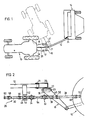
- a tractor 10 is connected by way of a drawbar (or tongue) 12 to an implement 14 which in the present instance is a mower-conditioner.
- the drawbar 12 supports a U-shaped yoke 16 of which the arms 17 of the "U" are attached to lower links 18 of a standard 3- point hitch of the tractor and so are aligned with , the latter's fore-and-aft direction.
- the yoke 16 is suspended from two channel-shaped supports 20 and 22 which are rigidly attached to each other at right angles with support 20 above support 22 and which are connected to the drawbar 12 and yoke 16 respectively by vertical pivot pin 21 and horizontal pivot pin 23 (shown for example in Figure 2).
- the yoke thus has two degrees of freedom of movement relative to the drawbar 12.
- the drawbar 12 is connected at pivot 24 to the left hand side of the implement 14.
- the disposition of the tractor 10 and mower-conditioner 14 indicated in full lines in Figure 1 is the normal working position which is used as the implement 14 is pulled behind, and somewhat to one side of, the tractor in a pass over a grass crop.
- the tractor 10 is turned at the end of one pass to be aligned for the next pass, and the tractor position at the turn is shown in broken lines, the fore-and-aft direction of the tractor being at right angles to the drawbar 12.
- power is transmitted from the tractor 10 to the implement 14 by way of a drive line 26 which for the major part of its length underlies the drawbar 12.
- the main components are a forward primary shaft 28, a rearward secondary shaft 30, and two connected double cross bearing constant velocity universal joints 32 and 34 between the shafts 28 and 30.
- the secondary shaft 30 is illustrated as being short for convenience in the drawing, but in reality it is about double the length of the primary shaft 28.
- a second support for the drive line 26 is provided by a downwardly extending channel bracket or sling 42 (shown partially broken away) on the drawbar 12, and a support bearing 44 for an intermediate shaft 46 connecting the joint 34 to the secondary shaft 30 is disposed on the underside of the base of the channel. Double cross bearing constant velocity joints are readily available and so will not be described.
- the primary shaft 28 is connected through a universal joint 48 to a coupling 50 for a power take-off shaft (not shown) of the tractor.
- the primary shaft 28 is attached, via a universal joint 52, to the intermediate shaft 40 which in turn is connected to the double cross bearing joint 32 which is connected through a shaft 54 to the other double cross bearing joint 34 and thence to the intermediate shaft 46.
- the shaft 46 is connected, via a universal joint 56, to the secondary shaft 30 which is connected, through yet another universal joint 58, to a coupler 60 to the input (not shown) on the implement 14.
- Figure 2 shows the drive line 26 in its normal working position corresponding to that in full lines in Figure 1, whilst Figure 3 illustrates the position which the drive line assumes when the tractor is in the broken line position at turn around between passes. It will readily be seen that if the implement is to continue functioning at turn around, then the power must turn through a total of 90°. With the arrangement illustrated the power is taken firstly through a working angle of 22 1/2° on the input side of the double cross bearing universal joint 32 and through a further 22 1/2° on the output side of the joint. Similarly at the joint 34 the power undergoes successively two working angle changes of 22 1/2°.
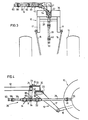
- a horizontal lever arm 68 is rigidly attached to the pivot post 66, and a Bowden-type cable 70 is connected to the free end of the arm 68 and secured to a point 72 on the support 20 with the outer (tube) part of the cable 70 secured at various points, e.g. at point 73.
- the support 20 is L-shaped in cross section whereas in the first example ( Figures 2 and 3) as already mentioned it is channel-shaped, whilst in both examples the support 22 is channel-shaped.
- the cable is so arranged as to cause movement of the arm 68 and hence of the support bearing 64 through an angle which is half the angle through which the support 20 and the yoke 16 turn either clockwise or anti-clockwise.
- the drive line 26 in the second embodiment consists (starting from the tractor end and moving rearwardly) of the coupling 50, the primary shaft 28, the double cross bearing joint 32, an intermediate shaft 74, the double cross bearing joint 34, the secondary shaft 30 and finally the coupling 60.
- the supports 20 and 22 can simply consist of the respective arms of an L-shaped rod one arm of which extends vertically upwardly through the drawbar 12 and the other of which extends horizontally through the cross beam 36 of the yoke 16, the pivotal movement being as already described.
- one of the joints 32 and 34 may be a single cross bearing universal joint, but for efficient power transmission through large angles in tight turns it is desirable to employ at least two such joints in the drive line.
Landscapes
- Life Sciences & Earth Sciences (AREA)
- Engineering & Computer Science (AREA)
- Mechanical Engineering (AREA)
- Soil Sciences (AREA)
- Environmental Sciences (AREA)
- Zoology (AREA)
- Agricultural Machines (AREA)
- Soil Working Implements (AREA)
- Harvester Elements (AREA)
- Valve Device For Special Equipments (AREA)
- Control Of Motors That Do Not Use Commutators (AREA)
- Valve-Gear Or Valve Arrangements (AREA)
Claims (5)
Priority Applications (1)
| Application Number | Priority Date | Filing Date | Title |
|---|---|---|---|
| AT86101791T ATE45661T1 (de) | 1985-03-05 | 1986-02-13 | Geraeteanbauvorrichtung fuer schlepper. |
Applications Claiming Priority (2)
| Application Number | Priority Date | Filing Date | Title |
|---|---|---|---|
| GB8505578 | 1985-03-05 | ||
| GB08505578A GB2172086B (en) | 1985-03-05 | 1985-03-05 | An implement with a drive line for transmitting power from a tractor to the implement |
Publications (2)
| Publication Number | Publication Date |
|---|---|
| EP0196427A1 EP0196427A1 (de) | 1986-10-08 |
| EP0196427B1 true EP0196427B1 (de) | 1989-08-23 |
Family
ID=10575431
Family Applications (1)
| Application Number | Title | Priority Date | Filing Date |
|---|---|---|---|
| EP86101791A Expired EP0196427B1 (de) | 1985-03-05 | 1986-02-13 | Geräteanbauvorrichtung für Schlepper |
Country Status (4)
| Country | Link |
|---|---|
| EP (1) | EP0196427B1 (de) |
| AT (1) | ATE45661T1 (de) |
| DE (1) | DE3665123D1 (de) |
| GB (2) | GB2172086B (de) |
Cited By (2)
| Publication number | Priority date | Publication date | Assignee | Title |
|---|---|---|---|---|
| EP0512326A1 (de) * | 1991-05-02 | 1992-11-11 | Deere & Company | Deichsel |
| DE19608579A1 (de) * | 1996-03-06 | 1997-09-25 | Deere & Co | Anhängevorrichtung |
Families Citing this family (3)
| Publication number | Priority date | Publication date | Assignee | Title |
|---|---|---|---|---|
| GB2200606B (en) * | 1987-01-30 | 1991-01-30 | Esarco Ltd | Improved all-terrain vehicle |
| DE29704121U1 (de) * | 1997-03-07 | 1997-05-15 | Maschinenfabrik Rau GmbH, 73235 Weilheim | Fahrbare Spritzeinrichtung |
| DE102008048403B4 (de) | 2008-09-23 | 2012-03-15 | Lemken Gmbh & Co. Kg | Bodenbearbeitungsgerät |
Family Cites Families (12)
| Publication number | Priority date | Publication date | Assignee | Title |
|---|---|---|---|---|
| US2605853A (en) * | 1947-10-23 | 1952-08-05 | Carl E Swenson | Power take-off joint assembly |
| DE1117950C2 (de) * | 1957-12-07 | 1962-05-24 | Friedrich Moertl | Führung eines kardanischen Doppelgelenkes |
| GB894806A (en) * | 1959-03-30 | 1962-04-26 | Ford Motor Co | Universal joint |
| GB972445A (en) * | 1962-05-22 | 1964-10-14 | Eric Walden | Improvements in or relating to universal joints and like couplings |
| US3427824A (en) * | 1967-02-13 | 1969-02-18 | Martin Mayrath | Universal joint drive connection for large angles of shaft deviation |
| DE1755592A1 (de) * | 1968-05-27 | 1971-08-26 | Walterscheid Kg Jean | Zapfwellen-Antriebsvorrichtung fuer Landmaschinen |
| US3908398A (en) * | 1974-03-29 | 1975-09-30 | Gehl Co | Articulated vehicle assembly |
| US4075871A (en) * | 1976-02-27 | 1978-02-28 | General Motors Corporation | Double Cardan joint with elastomeric centering means |
| DE2644671C2 (de) * | 1976-10-02 | 1978-11-09 | Jean Walterscheid Gmbh, 5204 Lohmar | Weitwinkelgelenk |
| FR2395424A1 (fr) * | 1977-06-23 | 1979-01-19 | Ferodo Sa | Transmission sensiblement homocinetique |
| DE2802572C2 (de) * | 1978-01-21 | 1982-07-22 | Jean Walterscheid Gmbh, 5204 Lohmar | Homokinetisches Doppelgelenk für große Beugewinkel |
| NL8100145A (nl) * | 1981-01-14 | 1982-08-02 | Miedema Landbouwwerktuigen | Koppeling tussen een trekker en de trekboom van een te trekken voertuig of werktuig. |
-
1985
- 1985-03-05 GB GB08505578A patent/GB2172086B/en not_active Expired
- 1985-08-12 GB GB08520173A patent/GB2172087B/en not_active Expired
-
1986
- 1986-02-13 AT AT86101791T patent/ATE45661T1/de not_active IP Right Cessation
- 1986-02-13 DE DE8686101791T patent/DE3665123D1/de not_active Expired
- 1986-02-13 EP EP86101791A patent/EP0196427B1/de not_active Expired
Cited By (4)
| Publication number | Priority date | Publication date | Assignee | Title |
|---|---|---|---|---|
| EP0512326A1 (de) * | 1991-05-02 | 1992-11-11 | Deere & Company | Deichsel |
| DE19608579A1 (de) * | 1996-03-06 | 1997-09-25 | Deere & Co | Anhängevorrichtung |
| US5873229A (en) * | 1996-03-06 | 1999-02-23 | Deere & Company | Coupling arrangement |
| DE19608579C2 (de) * | 1996-03-06 | 1999-03-04 | Deere & Co | Anhängevorrichtung |
Also Published As
| Publication number | Publication date |
|---|---|
| GB2172086B (en) | 1989-01-11 |
| GB8505578D0 (en) | 1985-04-03 |
| GB2172086A (en) | 1986-09-10 |
| DE3665123D1 (en) | 1989-09-28 |
| EP0196427A1 (de) | 1986-10-08 |
| GB2172087A (en) | 1986-09-10 |
| GB8520173D0 (en) | 1985-09-18 |
| GB2172087B (en) | 1988-12-21 |
| ATE45661T1 (de) | 1989-09-15 |
Similar Documents
| Publication | Publication Date | Title |
|---|---|---|
| US5531283A (en) | Drivetrain and load bearing swivel hitch assemby and combine incorporating same | |
| US4899523A (en) | Mower | |
| US5522208A (en) | Farm machine and connecting and transmission device therefor | |
| US3557892A (en) | Hitch adapter | |
| US20090107096A1 (en) | Drive System for an Agricultural Machine with a Floating Work Tool | |
| US5152357A (en) | Swivel hitch for connecting an implement to a tractor | |
| RU2003120796A (ru) | Линия гидропривода и сцепное устройство для прицепного оборудования | |
| EP0316899A2 (de) | Schlepper und durch den Schlepper gezogenes Gerät | |
| USRE35835E (en) | Device for attaching an agricultural implement to a tractor | |
| US5722222A (en) | Center-pivot mower-conditioner drive | |
| EP0196427A1 (de) | Geräteanbauvorrichtung für Schlepper | |
| EP0196426B1 (de) | Geräteanbauvorrichtung für Schlepper | |
| US5186271A (en) | Swivel hitch with improved mounting of lower gearbox | |
| US5964664A (en) | CV drive shaft construction | |
| US4398617A (en) | Rear axle-drawbar oscillation support system | |
| GB2171884A (en) | Hitching arrangement for an implement pulled by a tractor | |
| US5158500A (en) | Primary drive line and coupling for agricultural implements | |
| US5265403A (en) | Draft tongue for connecting PTO-driven implement to draft links of a towing vehicle | |
| US11997938B2 (en) | Articulated apparatus for towing a rotary driven implement from a towing vehicle | |
| US5099937A (en) | Swivel hitch with reorientable lower gearbox | |
| WO2008037006A1 (en) | Machinery hitches | |
| GB2095525A (en) | Rotary side-delivery hay rake | |
| US1827070A (en) | Power take-off mechanism for tractors | |
| US4281848A (en) | Joint for articulated vehicles | |
| US6481192B1 (en) | Steering tube for pivotally rotating a hay harvester gearbox |
Legal Events
| Date | Code | Title | Description |
|---|---|---|---|
| PUAI | Public reference made under article 153(3) epc to a published international application that has entered the european phase |
Free format text: ORIGINAL CODE: 0009012 |
|
| AK | Designated contracting states |
Kind code of ref document: A1 Designated state(s): AT BE CH DE FR GB LI NL SE |
|
| 17P | Request for examination filed |
Effective date: 19861103 |
|
| 17Q | First examination report despatched |
Effective date: 19880701 |
|
| GRAA | (expected) grant |
Free format text: ORIGINAL CODE: 0009210 |
|
| AK | Designated contracting states |
Kind code of ref document: B1 Designated state(s): AT BE CH DE FR GB LI NL SE |
|
| REF | Corresponds to: |
Ref document number: 45661 Country of ref document: AT Date of ref document: 19890915 Kind code of ref document: T |
|
| REF | Corresponds to: |
Ref document number: 3665123 Country of ref document: DE Date of ref document: 19890928 |
|
| ET | Fr: translation filed | ||
| PLBE | No opposition filed within time limit |
Free format text: ORIGINAL CODE: 0009261 |
|
| STAA | Information on the status of an ep patent application or granted ep patent |
Free format text: STATUS: NO OPPOSITION FILED WITHIN TIME LIMIT |
|
| 26N | No opposition filed | ||
| PGFP | Annual fee paid to national office [announced via postgrant information from national office to epo] |
Ref country code: SE Payment date: 19920108 Year of fee payment: 7 |
|
| PGFP | Annual fee paid to national office [announced via postgrant information from national office to epo] |
Ref country code: CH Payment date: 19920120 Year of fee payment: 7 |
|
| PGFP | Annual fee paid to national office [announced via postgrant information from national office to epo] |
Ref country code: AT Payment date: 19920204 Year of fee payment: 7 |
|
| PG25 | Lapsed in a contracting state [announced via postgrant information from national office to epo] |
Ref country code: AT Effective date: 19930213 |
|
| PG25 | Lapsed in a contracting state [announced via postgrant information from national office to epo] |
Ref country code: SE Effective date: 19930214 |
|
| PGFP | Annual fee paid to national office [announced via postgrant information from national office to epo] |
Ref country code: BE Payment date: 19930224 Year of fee payment: 8 |
|
| PG25 | Lapsed in a contracting state [announced via postgrant information from national office to epo] |
Ref country code: LI Effective date: 19930228 Ref country code: CH Effective date: 19930228 |
|
| REG | Reference to a national code |
Ref country code: CH Ref legal event code: PL |
|
| PGFP | Annual fee paid to national office [announced via postgrant information from national office to epo] |
Ref country code: GB Payment date: 19940114 Year of fee payment: 9 |
|
| PG25 | Lapsed in a contracting state [announced via postgrant information from national office to epo] |
Ref country code: BE Effective date: 19940228 |
|
| BERE | Be: lapsed |
Owner name: DEERE & CY Effective date: 19940228 |
|
| EUG | Se: european patent has lapsed |
Ref document number: 86101791.1 Effective date: 19930912 |
|
| PG25 | Lapsed in a contracting state [announced via postgrant information from national office to epo] |
Ref country code: GB Effective date: 19950213 |
|
| GBPC | Gb: european patent ceased through non-payment of renewal fee |
Effective date: 19950213 |
|
| PGFP | Annual fee paid to national office [announced via postgrant information from national office to epo] |
Ref country code: FR Payment date: 20020130 Year of fee payment: 17 |
|
| PGFP | Annual fee paid to national office [announced via postgrant information from national office to epo] |
Ref country code: DE Payment date: 20020219 Year of fee payment: 17 |
|
| PGFP | Annual fee paid to national office [announced via postgrant information from national office to epo] |
Ref country code: NL Payment date: 20020226 Year of fee payment: 17 |
|
| PG25 | Lapsed in a contracting state [announced via postgrant information from national office to epo] |
Ref country code: NL Free format text: LAPSE BECAUSE OF NON-PAYMENT OF DUE FEES Effective date: 20030901 |
|
| PG25 | Lapsed in a contracting state [announced via postgrant information from national office to epo] |
Ref country code: DE Free format text: LAPSE BECAUSE OF NON-PAYMENT OF DUE FEES Effective date: 20030902 |
|
| PG25 | Lapsed in a contracting state [announced via postgrant information from national office to epo] |
Ref country code: FR Free format text: LAPSE BECAUSE OF NON-PAYMENT OF DUE FEES Effective date: 20031031 |
|
| NLV4 | Nl: lapsed or anulled due to non-payment of the annual fee |
Effective date: 20030901 |
|
| REG | Reference to a national code |
Ref country code: FR Ref legal event code: ST |