EP0196494A1 - Machine à souder pour le soudage de languettes sur des tôles - Google Patents
Machine à souder pour le soudage de languettes sur des tôles Download PDFInfo
- Publication number
- EP0196494A1 EP0196494A1 EP86103007A EP86103007A EP0196494A1 EP 0196494 A1 EP0196494 A1 EP 0196494A1 EP 86103007 A EP86103007 A EP 86103007A EP 86103007 A EP86103007 A EP 86103007A EP 0196494 A1 EP0196494 A1 EP 0196494A1
- Authority
- EP
- European Patent Office
- Prior art keywords
- sheet metal
- welding
- tab
- conveyor
- machine according
- Prior art date
- Legal status (The legal status is an assumption and is not a legal conclusion. Google has not performed a legal analysis and makes no representation as to the accuracy of the status listed.)
- Granted
Links
Images


Classifications
-
- B—PERFORMING OPERATIONS; TRANSPORTING
- B21—MECHANICAL METAL-WORKING WITHOUT ESSENTIALLY REMOVING MATERIAL; PUNCHING METAL
- B21D—WORKING OR PROCESSING OF SHEET METAL OR METAL TUBES, RODS OR PROFILES WITHOUT ESSENTIALLY REMOVING MATERIAL; PUNCHING METAL
- B21D43/00—Feeding, positioning or storing devices combined with, or arranged in, or specially adapted for use in connection with, apparatus for working or processing sheet metal, metal tubes or metal profiles; Associations therewith of cutting devices
- B21D43/02—Advancing work in relation to the stroke of the die or tool
- B21D43/021—Control or correction devices in association with moving strips
- B21D43/023—Centering devices, e.g. edge guiding
-
- B—PERFORMING OPERATIONS; TRANSPORTING
- B21—MECHANICAL METAL-WORKING WITHOUT ESSENTIALLY REMOVING MATERIAL; PUNCHING METAL
- B21D—WORKING OR PROCESSING OF SHEET METAL OR METAL TUBES, RODS OR PROFILES WITHOUT ESSENTIALLY REMOVING MATERIAL; PUNCHING METAL
- B21D43/00—Feeding, positioning or storing devices combined with, or arranged in, or specially adapted for use in connection with, apparatus for working or processing sheet metal, metal tubes or metal profiles; Associations therewith of cutting devices
- B21D43/02—Advancing work in relation to the stroke of the die or tool
- B21D43/026—Combination of two or more feeding devices provided for in B21D43/04 - B21D43/18
-
- B—PERFORMING OPERATIONS; TRANSPORTING
- B21—MECHANICAL METAL-WORKING WITHOUT ESSENTIALLY REMOVING MATERIAL; PUNCHING METAL
- B21D—WORKING OR PROCESSING OF SHEET METAL OR METAL TUBES, RODS OR PROFILES WITHOUT ESSENTIALLY REMOVING MATERIAL; PUNCHING METAL
- B21D43/00—Feeding, positioning or storing devices combined with, or arranged in, or specially adapted for use in connection with, apparatus for working or processing sheet metal, metal tubes or metal profiles; Associations therewith of cutting devices
- B21D43/02—Advancing work in relation to the stroke of the die or tool
- B21D43/18—Advancing work in relation to the stroke of the die or tool by means in pneumatic or magnetic engagement with the work
-
- B—PERFORMING OPERATIONS; TRANSPORTING
- B21—MECHANICAL METAL-WORKING WITHOUT ESSENTIALLY REMOVING MATERIAL; PUNCHING METAL
- B21D—WORKING OR PROCESSING OF SHEET METAL OR METAL TUBES, RODS OR PROFILES WITHOUT ESSENTIALLY REMOVING MATERIAL; PUNCHING METAL
- B21D43/00—Feeding, positioning or storing devices combined with, or arranged in, or specially adapted for use in connection with, apparatus for working or processing sheet metal, metal tubes or metal profiles; Associations therewith of cutting devices
- B21D43/20—Storage arrangements; Piling or unpiling
-
- B—PERFORMING OPERATIONS; TRANSPORTING
- B23—MACHINE TOOLS; METAL-WORKING NOT OTHERWISE PROVIDED FOR
- B23K—SOLDERING OR UNSOLDERING; WELDING; CLADDING OR PLATING BY SOLDERING OR WELDING; CUTTING BY APPLYING HEAT LOCALLY, e.g. FLAME CUTTING; WORKING BY LASER BEAM
- B23K11/00—Resistance welding; Severing by resistance heating
- B23K11/002—Resistance welding; Severing by resistance heating specially adapted for particular articles or work
- B23K11/0033—Welding locally a thin plate to a large piece
Definitions
- the invention relates to a welding machine with at least one pair of welding electrodes for welding tabs to sheet metal parts, in particular can parts that can be torn open, according to an electrical resistance welding method.
- the method and device for welding tabs to sheet metal parts are the subject of older patent applications of the applicant which were not previously published at the time of priority application (CH application No. 3404 / 84-6, or EP-PA 85.107.150.6 and CH - Application No. 4582 / 84-2, or EP-PA 85.111.945.3) in which it remains to be seen how the sheet metal parts and tabs are prepared for welding.
- the present invention has for its object to provide a welding machine of the type described above, which is capable of welding tabs to sheet metal parts in short cycle times.
- the welding machine according to the invention is preferably further developed in that the sheet metal conveyor has a roller conveyor with a lateral boundary and several groups of rollers, between which the sheet metal parts can be moved one behind the other, the rollers bearing with prestress against the top and bottom of the sheet metal part and at least some rollers at an acute angle Movement direction of the sheet metal part are arranged and push it against the lateral boundary.
- a stamping roller for stamping at least two parallel lines of weakness delimiting a tear strip into each sheet metal part is expediently arranged between two groups of rollers and the positioning device is set such that the tear strip gets between the welding electrodes.
- the invention can also be designed in that several groups of rollers, between which the sheet metal parts are arranged during welding, are freely rotatable, and that the positioning device has a driver with which the sheet metal parts between the rollers of these groups can be moved into a welding position .
- the sheet metal conveyor can have an additional reciprocating driver with which the sheet metal parts can be moved further from the welding position.
- the positioning device can have a stop which can be moved intermittently into the movement path of the sheet metal parts.
- the sheet metal conveyor can also have at least one cyclically movable transverse conveyor section which extends transversely to the lines of weakness.
- the cross conveyor line can have drivers which are aligned in cycles with the lateral limitation of the roller conveyor.
- a guide rail is arranged on the side next to the transverse conveyor path, along which the sheet metal parts, with their edge arranged transversely to the lines of weakness and moving through between the rollers, can be moved along.
- a section of the lateral guide rail extends in the vicinity of the welding electrodes and the positioning device is designed to generate a force in the direction of the lines of weakness that the sheet metal part lying between the welding electrodes on the mentioned section of the guide rail holds tight.
- the tab conveyor can have at least one receptacle for a tab, which can be moved from the area of a stamp for punching the tab from a sheet metal strip into the area of the welding electrodes and back.
- the tab conveyor can be rotated in cycles about a central axis and has a plurality of receptacles for each tab which are arranged radially around this axis at equal circumferential intervals.
- This embodiment can be further configured in that the receptacles are delimited radially outwards by an edge of the tab conveyor and open radially inwards into an opening through which one of the welding electrodes can be moved in the direction of the other.
- Each receptacle can be connected to a suction channel for sucking the punched tab.
- the stamp can have a suction cup for temporarily holding the punched tab.
- the welding electrodes can be moved in a forceps-like manner in relation to one another in a manner customary in spot welding. According to the invention, it is particularly expedient if an electrode wire is arranged between the welding electrodes which can be moved in this way and the can plate or the tab, which can be moved in cycles.
- electrode wire is known for continuous longitudinal seam welding of can bodies (DE-C 1 017 042); an electrode wire is passed between two overlapping edge regions of a cylindrically rolled sheet metal part and a roller-shaped electrode carrier, on which the electrode carriers roll continuously. Electrode wire, however, has so far not been used for spot welding; this use according to the invention is extremely economical, since flawless welds during continuous operation of the welding machine according to the invention without any special measures, for example that suggested in one of the older applications (CH application No. 4582 / 84-2 or E PP A 85.111.945.3) genes, can be achieved if the electrode wire is moved a small step after welding each tab.
- the positioning device is assigned two pairs of welding electrodes and two tab conveyors for welding one tab each to both ends of a common tear strip or to one end of two tear strips.
- the performance of the welding machine according to the invention can be doubled, since the sheet metal parts with two welded-on tabs can then be cut transversely to the tear strip or between two tear strips parallel to these, so that two tin parts, each with a tab, result from each sheet metal part then, for example, a round can frame can be formed.
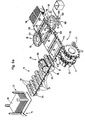
- the welding machines shown have the task of providing rectangular sheet metal parts 10 made of tinplate, for example 0.2 mm thick, each with a tear strip 11 parallel to the longitudinal sides of the sheet metal parts or with two such tear strips (FIG. 6a) and one at each end of these tear strips To weld tab 12.
- Each of the machines shown is assigned a magazine 13 in which the sheet metal parts 10 are kept stacked ready.
- a stacking device 14 is arranged underneath the magazine 13, and this is followed by a sheet metal conveyor 15 which conveys the sheet metal parts 10 one after the other in a horizontal plane.
- the sheet metal conveyor 15 is assigned an embossing station 16 for embossing the tear strips 11, and this is followed by a positioning device 17, which positions the sheet metal parts one after the other in a precisely predetermined position in the working area of a tab conveyor 18 and a welding station 19 or two tab conveyors 18 and two welding stations 19 (Fig. 6a) holds.
- control shaft 20 is connected by a worm gear 21 to an eccentric 22 belonging to the stacker 14, on which a connecting rod 23 is mounted.
- the connecting rod 23 is connected in an articulated manner to a cross head 24, which has two suction cups 25 on its upper side and is guided up and down in a recess 26 in a table 27.
- the sheet metal conveyor 15 has several groups of lower rollers 31 and upper rollers 32, each of which can be rotated about a horizontal axis.
- the axes of the lower rollers 31 extend at right angles to the longitudinal edges of the sheet metal parts 10; the upper rollers 32 are skewed to the lower rollers 31 at a small angle and consequently endeavor to hold each sheet metal part 10 passing between the rollers 31 and 32 with one of its two longitudinal edges against a lateral boundary 33.
- the lateral boundary 33 is formed by a straight line of vertically mounted rollers.
- the last lower roller 31a (FIGS. 6 and 6a) is a magnetic roller which can be adjusted depending on the sheet length.
- the lower rollers 31 are fixed in place; some of them - in FIG. 1 the first to third lower rollers 31, in FIGS. 1 a and in FIGS. 6 and 6 a additionally lower rollers 31 arranged further to the right - can be driven in rotation by a motor (not shown); these roles are marked with an arrow 34.
- the upper rollers 32 are freely rotatable and are supported in a vertically resilient manner.
- FIG. 6a Behind the third (FIGS. 1 and la) and fifth (FIGS. 6 and 6a) rotatably drivable lower roller 31, a strong support roller 35 is mounted parallel to these rollers and above this, an embossing roller 36 is mounted parallel to the upper rollers 32 1, la and 6, a set of cutting edges of three annular cutting edges 37, according to FIG. 6a, however, has two sets of such cutting edges 37, which are arranged near each end of the embossing roller.
- Back-up roller 35 and embossing roller 36 can be driven in rotation at a speed matched to the peripheral speed of the lower rollers 31 and emboss one or two (FIG. 6a) tear strips 11 into each sheet metal part 10 passing between them, parallel to the longitudinal edges thereof.
- a second and a third worm drive 38 and 39 are arranged on the control shaft 20, each of which drives a driver 42 or 43 via a crank drive 40 or 41.
- the drivers 42 and 43 are each guided on a rod 44 parallel to the conveying direction of the sheet metal conveyor 15 and on a common guide bar 45.
- Each of the drivers 42 and 43 carries an upwardly resilient pawl 46 and 47.
- the driver 42 belongs to the positioning device 17; with his pawl 46 he engages behind a sheet metal part 10 between each Back-up roller 35 and embossing roller 36 has passed through.
- the pawl 46 pushes this sheet metal part 10 into a precisely predetermined position in which its tear strip 11 is in the working area of the welding station 19.
- the driver 43 can be assigned to the sheet metal conveyor 15; he has the task of further promoting the latter sheet metal part 10 after welding a tab 12 until it is carried along by a further driven lower roller 31.
- Fig. La differs from Fig. 1 essentially in that the drivers 42 and 43 together with the associated drives and pawls are omitted and the positioning device 17 has a movable in the path of movement of the sheet metal parts 10 stop 48 which is from the control shaft 20 is controlled via a cam plate 49 and a lever arrangement.
- the first and the second lower roller 31 following the support roller 35 each convey the sheet-metal part 10 provided with a tear strip 11 against the stop 48 in order to position it for welding a tab 12.
- the upper rollers 32 which are assigned to the latter driven lower rollers 31, are lifted off with a lifting device 50, which is also controlled by the cam plate 49, so that the rotating lower rollers 31 do not Leave traces on the sheet metal part 10.
- the tab conveyor 18 includes an essentially horizontal, circular plate 51, which can be rotated step by step by 90 ° about a vertical axis A and at circumferential intervals of likewise 90 ° each have a downwardly open receptacle 52 for a tab 12.
- the recordings 52 each contain a suction cup 53 which is connected to a suction channel 54.
- the plate 51 is fastened to a vertical shaft 55, which can also be driven in rotation from the control shaft 20, via a gear 56, and can be raised and lowered via a lifting device 57.
- a sheet metal strip 58 is guided along a secant of the circular plate 51 and a tab 12 is pre-punched at predetermined intervals.
- the free end of each tab 12 is turned over in the form of a triangle; in this regard, reference is made to one of the older patent applications mentioned (CH Application No. 4582 / 84-2, or EP-PA 85.111.945.3).
- the sheet metal strip 58 can be advanced step by step with a device, also not shown, which is also controlled by the control shaft 20, so that with each working cycle of the welding machine the foremost tab 12 still connected to the sheet metal strip comes to rest under one of the receptacles 52, in such a way that this tab 2 extends radially with respect to the axis A and the folded end of this tab lies outside the outer edge of the plate 51.
- this tab 12 which is still connected to the sheet metal strip 58, lies between a stamping die 59 and an up and down movable stamp 60 which separates the tab from the sheet metal strip 58 and temporarily holds it with a suction cup 61 attached to it until the tab lies securely in the associated receptacle 52 and is held by the drinking bowl 53 arranged there.
- the tab conveyor 18 is rotated through 90 ° about the axis A, as a result of which the tab 12 which was separated last reaches the welding station 19.
- two welding electrodes 62 and 63 are arranged vertically one above the other.
- the lower welding electrode 62 is stationary; the upper welding electrode 63 is attached via an adjustable threaded bolt 64 suspended from a lifting device 65 and resiliently biased against it downwards.
- the lifting device 65 is controlled by a lever linkage from the cam plate 49 or a corresponding control element, likewise driven by the central control shaft 20.
- the two welding electrodes 62 and 63 are connected to a welding transformer 66 and connected to a coolant circuit 67 in the usual manner in spot welding machines. Between the lower welding electrode 62 and the sheet metal part 10 positioned above it and between the upper welding electrode 63 and the tab 12 still held under it in the mentioned receptacle 52 of the plate 51, a section of an electrode wire 68 running transversely to the tear strips 11 is arranged.
- the electrode wire 68 has a flattened, rectangular cross section and is guided over deflection rollers (not shown in FIGS. 1 to 5) and can be moved in steps.
- the upper welding electrode 63 executes a downward stroke, with the secondary circuit of the welding transformer 66 being closed and the tab 12 with the tear strip 11 of the relevant sheet metal part 10 via the two named sections of the electrode wire 68, as well as the tab 12 and the sheet metal part 10 is welded.
- the tab conveyor 18 executes an upward stroke so that it releases the welded-on tab 12.
- the welding machine according to FIGS. 6 to 10 together with its variant according to FIG. 6a differs from that shown in FIGS. 1 to 5 initially in that behind the support roller 35 and embossing roller 36 only two lower rollers, which are driven, and a set of upper rollers Rollers 32 are arranged. Behind it extends in a horizontal plane perpendicular to the conveying direction of the sheet conveyor 15 and thus also at right angles to the tear strips 11, a cross conveyor 70, which in the example shown has two parallel roller chains 71 and drivers 72 arranged at intervals therefrom.
- the roller chains 71 also via the central control shaft 20, can be driven step-by-step such that, when they are at a standstill, a pair of drivers 72 is approximately aligned with the lateral boundary 33 of the sheet metal conveyor 15, with sufficient space between the latter and the preceding pair of drivers 72 for receiving one from the sheet metal conveyor 15 delivered sheet metal part 10 is free.
- This sheet metal part is pushed by the foremost driven lower roller 31a against a lateral guide rail 73 which extends parallel to the transverse conveyor path 70.
- the latter sheet metal part 10 after two conveying steps of the roller chains 71, reaches the welding station 19, in which this sheet metal part, with its narrow side facing the viewer in FIGS. 6 and 6a, bears against an end section of the guide rail 73.
- a slide 74 is assigned to the opposite narrow side of the sheet metal part 10, which ensures that the contact with the guide rail 73 is maintained and the sheet metal part is thereby positioned in the longitudinal direction of the tear strip 11.
- the sheet metal part 10 In the direction transverse to the tear strip 11, the sheet metal part 10 is positioned in that a stop 48 similar to that shown in Fig. La is moved up into an effective position.
- the plate conveyor 18 is largely comparable to that shown in FIGS. 1 to 5; however, its plate 51 has a downwardly projecting, circular outer edge 75 which delimits the receptacles 52 for the tabs 12 radially outward.
- the sheet metal strip 58 is arranged here such that the tab 12 positioned for dancing is directed radially inward with its folded end.
- the folded end of this tab 12 is below one of four openings 76, each associated with one of the receptacles 52 and so large that the upper welding electrode 63 together with it raisable and lowerable guide rollers 77 for the electrode wire 68 contact-free through each of these Breakthroughs 76 can be moved through.
- the variant according to FIG. 6a differs from FIG. 6 in that - apart from the already mentioned doubling of the cutting arrangement on the embossing roller 36 - a tab conveyor 18 and a welding station 19 are arranged on both sides of the cross conveyor section 70, so that at each end each of the two tear strips 11 embossed by the embossing roller 36 can each be welded to a tab.
- a conveyor belt 78 for conveying away the sheet metal parts 10 with welded-on tabs 12 is assigned to each of the welding machines shown.
- the conveyor belt 78 is shown in FIG. 10 since the transverse conveyor section 70 according to FIG. 6 is connected.
- An angled catch plate 79 is arranged behind the end of the conveyor belt 78, which drops the sheet metal parts 10 into a stack magazine 80.
- the sheet metal parts 10 according to FIG. 6a have been provided with two tear strips 11, to each of which a tab 12 has been welded, then these sheet metal parts are divided in the middle in a subsequent operation parallel to the tear strips.
- the embossing roller 36 shown in FIG. 6a to be replaced by the one shown in FIG. 6, which only creates a single tear strip 11 on each sheet metal part 10.
- two tabs 12 can be welded to one end of the tear strip 11 if the tab conveyors 18 and welding stations 19 shown in FIG. 6a are arranged diametrically opposite one another.
- the sheet metal part 10 provided in this way with two tabs 12 is then divided transversely to the tear strip 11 into two parts, each having a tab 12.
Landscapes
- Engineering & Computer Science (AREA)
- Mechanical Engineering (AREA)
- Resistance Welding (AREA)
- Auxiliary Devices For And Details Of Packaging Control (AREA)
- Absorbent Articles And Supports Therefor (AREA)
- Wire Processing (AREA)
- Arc Welding In General (AREA)
Applications Claiming Priority (2)
| Application Number | Priority Date | Filing Date | Title |
|---|---|---|---|
| CH1183/85A CH667414A5 (de) | 1985-03-18 | 1985-03-18 | Schweissmaschine zum anschweissen von laschen an blechteile. |
| CH1183/85 | 1985-03-18 |
Publications (2)
| Publication Number | Publication Date |
|---|---|
| EP0196494A1 true EP0196494A1 (fr) | 1986-10-08 |
| EP0196494B1 EP0196494B1 (fr) | 1988-11-02 |
Family
ID=4204440
Family Applications (1)
| Application Number | Title | Priority Date | Filing Date |
|---|---|---|---|
| EP86103007A Expired EP0196494B1 (fr) | 1985-03-18 | 1986-03-06 | Machine à souder pour le soudage de languettes sur des tôles |
Country Status (16)
| Country | Link |
|---|---|
| US (1) | US4728766A (fr) |
| EP (1) | EP0196494B1 (fr) |
| JP (1) | JPS61212487A (fr) |
| CN (1) | CN1004340B (fr) |
| AU (1) | AU591480B2 (fr) |
| BR (1) | BR8601174A (fr) |
| CA (1) | CA1250905A (fr) |
| CH (1) | CH667414A5 (fr) |
| DE (2) | DE3513703A1 (fr) |
| DK (1) | DK165282C (fr) |
| ES (1) | ES8700994A1 (fr) |
| FI (1) | FI86153C (fr) |
| GB (1) | GB2172830B (fr) |
| GR (1) | GR860709B (fr) |
| HU (1) | HU197242B (fr) |
| SU (1) | SU1572403A3 (fr) |
Cited By (5)
| Publication number | Priority date | Publication date | Assignee | Title |
|---|---|---|---|---|
| DE3929358C1 (fr) * | 1989-07-06 | 1990-10-25 | Elpatronic Ag, Zug, Ch | |
| EP0437797A3 (en) * | 1990-01-17 | 1992-07-22 | Elpatronic Ag | Installation for welding ear handles on plate for can bodies |
| EP0437798A3 (en) * | 1990-01-17 | 1992-07-22 | Elpatronic Ag | Installation for manufacturing and welding of earhandles on plate for can bodies |
| CN100471614C (zh) * | 2005-01-11 | 2009-03-25 | 铃木株式会社 | 用于片状薄板的传送器 |
| CN102305526A (zh) * | 2011-06-27 | 2012-01-04 | 肇庆理士电源技术有限公司 | 极板干燥设备 |
Families Citing this family (15)
| Publication number | Priority date | Publication date | Assignee | Title |
|---|---|---|---|---|
| CH668730A5 (de) * | 1985-10-30 | 1989-01-31 | Elpatronic Ag | Schweissmaschine zum anschweissen von laschen an blechteile. |
| CH668760A5 (de) * | 1985-11-01 | 1989-01-31 | Elpatronic Ag | Magazin zum stapeln von blechteilen, insbesondere fuer die herstellung von dosen. |
| CH670242A5 (fr) * | 1986-07-07 | 1989-05-31 | Elpatronic Ag | |
| CH678501A5 (fr) * | 1989-05-16 | 1991-09-30 | Elpatronic Ag | |
| DE59302885D1 (de) * | 1992-05-25 | 1996-07-18 | Elpatronic Ag | Verfahren zum Abstapeln einzelner Bleche von einem Blechstapel und Vorrichtung zur Durchführung des Verfahrens |
| CA2135038C (fr) * | 1994-11-03 | 2002-01-22 | Bob Bishop | Methode et appareillage pour le traitement et la manipulation automatiques de feuilles de metal vierges, soudees a la molette par ecrasement |
| DE59503065D1 (de) * | 1994-11-28 | 1998-09-10 | Elpatronic Ag | Verfahren zur Inbetriebnahme oder Umrüstung einer Zargenschweissmaschine sowie ein modulares Magazin zum Durchführen des Verfahrens |
| CN103008761B (zh) * | 2012-11-23 | 2016-08-17 | 张加录 | 一种自动印花滚剪机 |
| CN104668693B (zh) * | 2015-01-22 | 2016-05-18 | 福建省万达汽车玻璃工业有限公司 | 一种舌片自动焊接及检测流水线 |
| CN105344865B (zh) * | 2015-11-30 | 2018-02-16 | 郑州金泰制罐有限公司 | 一种金属片材传送校准装置 |
| CN105397170B (zh) * | 2015-11-30 | 2018-02-13 | 郑州金泰制罐有限公司 | 一种金属片材自动切割生产线 |
| CN107138640B (zh) * | 2017-07-08 | 2023-06-13 | 浙江宝捷机电有限公司 | 传送机构上的定位组件 |
| JP7027122B2 (ja) * | 2017-10-27 | 2022-03-01 | シロキ工業株式会社 | 車両用ドアサッシュのシーム溶接方法 |
| CN110802313B (zh) * | 2019-05-12 | 2024-05-31 | 山西天宝集团有限公司 | 一种组焊风电塔筒构件使用的工装 |
| CN111037292B (zh) * | 2019-12-26 | 2021-04-09 | 福耀集团(福建)机械制造有限公司 | 一种车辆玻璃舌片焊接设备 |
Citations (4)
| Publication number | Priority date | Publication date | Assignee | Title |
|---|---|---|---|---|
| US1978740A (en) * | 1928-01-27 | 1934-10-30 | M J B Co | Method of manufacturing can bodies |
| US2695941A (en) * | 1948-05-10 | 1954-11-30 | Continental Can Co | Key welding machine |
| GB1106729A (en) * | 1965-09-13 | 1968-03-20 | American Can Co | Improvements relating to the manufacture of cemented lap side seam container bodies |
| US3557338A (en) * | 1966-07-08 | 1971-01-19 | Trw Inc | Apparatus for welding parts to workpieces |
Family Cites Families (9)
| Publication number | Priority date | Publication date | Assignee | Title |
|---|---|---|---|---|
| US1308778A (en) * | 1919-07-08 | Chusetts | ||
| US1884683A (en) * | 1928-08-14 | 1932-10-25 | American Can Co | Machine for attaching keys to can tops |
| US2681968A (en) * | 1952-04-29 | 1954-06-22 | Pacific Can Company | Machine for welding can opening keys on can ends |
| DE1220535B (de) * | 1959-04-23 | 1966-07-07 | Kjellberg Esab G M B H | Rollenschweissmaschine zum Schweissen von Blechen |
| CH392370A (de) * | 1961-02-07 | 1965-05-15 | United Shoe Machinery Corp | Behälterdeckel |
| US3144955A (en) * | 1961-11-27 | 1964-08-18 | Compania Swift De La Plato Sa | Tear strip structure for cans |
| DE2642040C3 (de) * | 1976-09-18 | 1979-11-15 | W.C. Heraeus Gmbh, 6450 Hanau | Maschine zum automatischen Widerstandsschweißen von elektrische Kontakte bildenden Metallplättchen auf vorbestimmte Stellen eines Trägerbandes |
| US4214944A (en) * | 1978-05-23 | 1980-07-29 | American Can Company | Adhesive bonding of assembly parts |
| JPS59187544A (ja) * | 1983-04-09 | 1984-10-24 | 東洋製罐株式会社 | 巻取開封用接着缶及びその製法 |
-
1985
- 1985-03-18 CH CH1183/85A patent/CH667414A5/de not_active IP Right Cessation
- 1985-04-16 DE DE19853513703 patent/DE3513703A1/de active Granted
-
1986
- 1986-03-06 DE DE8686103007T patent/DE3661056D1/de not_active Expired
- 1986-03-06 EP EP86103007A patent/EP0196494B1/fr not_active Expired
- 1986-03-11 GB GB08605988A patent/GB2172830B/en not_active Expired
- 1986-03-12 HU HU861042A patent/HU197242B/hu not_active IP Right Cessation
- 1986-03-13 AU AU54707/86A patent/AU591480B2/en not_active Ceased
- 1986-03-13 FI FI861029A patent/FI86153C/fi not_active IP Right Cessation
- 1986-03-14 GR GR860709A patent/GR860709B/el unknown
- 1986-03-14 CA CA000504127A patent/CA1250905A/fr not_active Expired
- 1986-03-17 SU SU864027153A patent/SU1572403A3/ru active
- 1986-03-17 CN CN86101733.1A patent/CN1004340B/zh not_active Expired
- 1986-03-17 BR BR8601174A patent/BR8601174A/pt not_active IP Right Cessation
- 1986-03-17 US US06/840,440 patent/US4728766A/en not_active Expired - Lifetime
- 1986-03-18 JP JP61058478A patent/JPS61212487A/ja active Granted
- 1986-03-18 ES ES553122A patent/ES8700994A1/es not_active Expired
- 1986-03-18 DK DK125486A patent/DK165282C/da not_active IP Right Cessation
Patent Citations (4)
| Publication number | Priority date | Publication date | Assignee | Title |
|---|---|---|---|---|
| US1978740A (en) * | 1928-01-27 | 1934-10-30 | M J B Co | Method of manufacturing can bodies |
| US2695941A (en) * | 1948-05-10 | 1954-11-30 | Continental Can Co | Key welding machine |
| GB1106729A (en) * | 1965-09-13 | 1968-03-20 | American Can Co | Improvements relating to the manufacture of cemented lap side seam container bodies |
| US3557338A (en) * | 1966-07-08 | 1971-01-19 | Trw Inc | Apparatus for welding parts to workpieces |
Cited By (6)
| Publication number | Priority date | Publication date | Assignee | Title |
|---|---|---|---|---|
| DE3929358C1 (fr) * | 1989-07-06 | 1990-10-25 | Elpatronic Ag, Zug, Ch | |
| EP0437797A3 (en) * | 1990-01-17 | 1992-07-22 | Elpatronic Ag | Installation for welding ear handles on plate for can bodies |
| EP0437798A3 (en) * | 1990-01-17 | 1992-07-22 | Elpatronic Ag | Installation for manufacturing and welding of earhandles on plate for can bodies |
| CN100471614C (zh) * | 2005-01-11 | 2009-03-25 | 铃木株式会社 | 用于片状薄板的传送器 |
| CN102305526A (zh) * | 2011-06-27 | 2012-01-04 | 肇庆理士电源技术有限公司 | 极板干燥设备 |
| CN102305526B (zh) * | 2011-06-27 | 2013-10-16 | 肇庆理士电源技术有限公司 | 极板干燥设备 |
Also Published As
| Publication number | Publication date |
|---|---|
| CA1250905A (fr) | 1989-03-07 |
| CH667414A5 (de) | 1988-10-14 |
| SU1572403A3 (ru) | 1990-06-15 |
| FI861029A0 (fi) | 1986-03-13 |
| GB2172830A (en) | 1986-10-01 |
| BR8601174A (pt) | 1986-11-25 |
| JPH0318555B2 (fr) | 1991-03-12 |
| AU591480B2 (en) | 1989-12-07 |
| DK125486D0 (da) | 1986-03-18 |
| CN1004340B (zh) | 1989-05-31 |
| DK165282C (da) | 1993-03-22 |
| HU197242B (en) | 1989-03-28 |
| EP0196494B1 (fr) | 1988-11-02 |
| GR860709B (en) | 1986-07-15 |
| GB8605988D0 (en) | 1986-04-16 |
| AU5470786A (en) | 1986-09-25 |
| DK165282B (da) | 1992-11-02 |
| ES553122A0 (es) | 1986-12-01 |
| GB2172830B (en) | 1988-10-19 |
| HUT42976A (en) | 1987-09-28 |
| CN86101733A (zh) | 1986-09-24 |
| DE3513703A1 (de) | 1986-10-16 |
| DE3661056D1 (en) | 1988-12-08 |
| FI861029L (fi) | 1986-09-19 |
| US4728766A (en) | 1988-03-01 |
| ES8700994A1 (es) | 1986-12-01 |
| DE3513703C2 (fr) | 1989-03-09 |
| JPS61212487A (ja) | 1986-09-20 |
| FI86153C (fi) | 1992-07-27 |
| FI86153B (fi) | 1992-04-15 |
| DK125486A (da) | 1986-09-19 |
Similar Documents
| Publication | Publication Date | Title |
|---|---|---|
| EP0196494B1 (fr) | Machine à souder pour le soudage de languettes sur des tôles | |
| EP2036629A1 (fr) | Procédé et dispositif de coupe fine et de formage d'une pièce à usiner | |
| DE1611617A1 (de) | Vorrichtung zum Abstreifen von Stanzresten | |
| CH648257A5 (de) | Vorrichtung zur intermittierenden zufuehrung von gegenstaenden entlang einer zufuhrbahn. | |
| WO2008116527A1 (fr) | Dispositif de découpage et procédé de découpage | |
| EP0252349B1 (fr) | Dispositif transporteur pour tôles, en particulier sur une machine à souder des boîtes | |
| DE1131979B (de) | Stapelvorrichtung fuer bogenfoermiges Material | |
| DE2306213A1 (de) | Foerdervorrichtung | |
| DE3541012C1 (de) | Schweißmaschine zum Anschweißen von Laschen an Blechteile | |
| DE2250682C3 (de) | Vorrichtung zum Einbringen von Gegenständen in einen Verpackungskarton | |
| DE3730132C2 (fr) | ||
| DE2748228C2 (de) | Verfahren zum fortlaufenden Transport von durch einen Stanzstempel ausgestanzten einzelnen Stanzteilen für elektrische Geräte zu einer Stapelvorrichtung und Vorrichtung zur Durchführung des Verfahrens | |
| DE4008000C1 (fr) | ||
| DE2009138B2 (de) | Einrichtung zum kontinuierlichen Abtransport von Werkstücken | |
| DE69316573T2 (de) | Werkzeug zum Formen von Dosendeckel unterschiedlicher Durchmesser | |
| EP0344741B1 (fr) | Dispositif d'amenée de tôles à un outil d'emboutissage | |
| DE3150045A1 (de) | Zufuehreinrichtung fuer blechstreifenstapel zur zufuhr zu einem stanzautomaten | |
| DE2412260A1 (de) | Vorrichtung zum schneiden und positionieren von platinen in pressen | |
| EP0123065A2 (fr) | Machine à scier pour découper des pièces d'un profilé | |
| DE1611617C3 (de) | Vorrichtung zum Abstreifen von Stanzresten | |
| DE2421088C3 (de) | Einrichtung zum Ausrichten von Statorblechen für elektrische Maschinen | |
| WO2005077762A1 (fr) | Dispositif d'application sur des objets, de parties de feuille provenant d'une bande de feuille mince | |
| DE382692C (de) | Maschine zum Herstellen und Einlegen von Dichtungsringen in Metallbuechsenboeden | |
| AT135620B (de) | Maschine zur Herstellung von U-förmigen, an einem Schenkel gezahnten Blechstreifen zur Verbindung von Teilen von Schachteln, Kisten u. dgl. | |
| EP0437798A2 (fr) | Installation pour la fabrication et le soudage d'anneaux à oreilles sur des platins pour viroles de boîtes à conserves |
Legal Events
| Date | Code | Title | Description |
|---|---|---|---|
| PUAI | Public reference made under article 153(3) epc to a published international application that has entered the european phase |
Free format text: ORIGINAL CODE: 0009012 |
|
| AK | Designated contracting states |
Kind code of ref document: A1 Designated state(s): CH DE FR GB IT LI NL SE |
|
| 17P | Request for examination filed |
Effective date: 19860823 |
|
| 17Q | First examination report despatched |
Effective date: 19870915 |
|
| GRAA | (expected) grant |
Free format text: ORIGINAL CODE: 0009210 |
|
| AK | Designated contracting states |
Kind code of ref document: B1 Designated state(s): CH DE FR GB IT LI NL SE |
|
| GBT | Gb: translation of ep patent filed (gb section 77(6)(a)/1977) | ||
| REF | Corresponds to: |
Ref document number: 3661056 Country of ref document: DE Date of ref document: 19881208 |
|
| ET | Fr: translation filed | ||
| ITF | It: translation for a ep patent filed | ||
| PLBE | No opposition filed within time limit |
Free format text: ORIGINAL CODE: 0009261 |
|
| STAA | Information on the status of an ep patent application or granted ep patent |
Free format text: STATUS: NO OPPOSITION FILED WITHIN TIME LIMIT |
|
| 26N | No opposition filed | ||
| ITTA | It: last paid annual fee | ||
| EAL | Se: european patent in force in sweden |
Ref document number: 86103007.0 |
|
| REG | Reference to a national code |
Ref country code: CH Ref legal event code: PFA Free format text: ELPATRONIC AG,HERTIZENTRUM 6,6303 ZUG (CH) TRANSFER- ELPATRONIC AG,INDUSTRIESTRASSE 35,8962 BERGDIETIKON (CH) |
|
| REG | Reference to a national code |
Ref country code: GB Ref legal event code: IF02 |
|
| PGFP | Annual fee paid to national office [announced via postgrant information from national office to epo] |
Ref country code: GB Payment date: 20050221 Year of fee payment: 20 |
|
| PGFP | Annual fee paid to national office [announced via postgrant information from national office to epo] |
Ref country code: DE Payment date: 20050309 Year of fee payment: 20 |
|
| PGFP | Annual fee paid to national office [announced via postgrant information from national office to epo] |
Ref country code: SE Payment date: 20050310 Year of fee payment: 20 Ref country code: CH Payment date: 20050310 Year of fee payment: 20 |
|
| PGFP | Annual fee paid to national office [announced via postgrant information from national office to epo] |
Ref country code: FR Payment date: 20050311 Year of fee payment: 20 |
|
| PGFP | Annual fee paid to national office [announced via postgrant information from national office to epo] |
Ref country code: IT Payment date: 20050316 Year of fee payment: 20 |
|
| PGFP | Annual fee paid to national office [announced via postgrant information from national office to epo] |
Ref country code: NL Payment date: 20050322 Year of fee payment: 20 |
|
| PG25 | Lapsed in a contracting state [announced via postgrant information from national office to epo] |
Ref country code: GB Free format text: LAPSE BECAUSE OF EXPIRATION OF PROTECTION Effective date: 20060305 |
|
| PG25 | Lapsed in a contracting state [announced via postgrant information from national office to epo] |
Ref country code: NL Free format text: LAPSE BECAUSE OF EXPIRATION OF PROTECTION Effective date: 20060306 |
|
| REG | Reference to a national code |
Ref country code: GB Ref legal event code: PE20 |
|
| REG | Reference to a national code |
Ref country code: CH Ref legal event code: PL |
|
| NLV7 | Nl: ceased due to reaching the maximum lifetime of a patent |
Effective date: 20060306 |
|
| EUG | Se: european patent has lapsed |