EP0196501A2 - Dispositif pour échanger un cylindre d'impression dans une rotative - Google Patents
Dispositif pour échanger un cylindre d'impression dans une rotative Download PDFInfo
- Publication number
- EP0196501A2 EP0196501A2 EP86103157A EP86103157A EP0196501A2 EP 0196501 A2 EP0196501 A2 EP 0196501A2 EP 86103157 A EP86103157 A EP 86103157A EP 86103157 A EP86103157 A EP 86103157A EP 0196501 A2 EP0196501 A2 EP 0196501A2
- Authority
- EP
- European Patent Office
- Prior art keywords
- strips
- unloading
- loading
- plate
- pressure cylinder
- Prior art date
- Legal status (The legal status is an assumption and is not a legal conclusion. Google has not performed a legal analysis and makes no representation as to the accuracy of the status listed.)
- Granted
Links
Images

Classifications
-
- B—PERFORMING OPERATIONS; TRANSPORTING
- B41—PRINTING; LINING MACHINES; TYPEWRITERS; STAMPS
- B41F—PRINTING MACHINES OR PRESSES
- B41F9/00—Rotary intaglio printing presses
- B41F9/06—Details
- B41F9/18—Auxiliary devices for exchanging forme cylinders
-
- B—PERFORMING OPERATIONS; TRANSPORTING
- B41—PRINTING; LINING MACHINES; TYPEWRITERS; STAMPS
- B41F—PRINTING MACHINES OR PRESSES
- B41F13/00—Common details of rotary presses or machines
- B41F13/08—Cylinders
- B41F13/20—Supports for bearings or supports for forme, offset, or impression cylinders
Definitions
- the above invention relates to a device for replacing the printing cylinder for a rotary printing press.
- swivel-mounted arms and / or arms that can be fixed in a horizontal position are usually provided on the two side machine stands and serve as receiving devices for the ends of the corresponding printing cylinder that is removed from the printing unit or inserted into it should.
- a pressure cylinder While unloading a pressure cylinder, it is dismantled and moved with rolling movement on the horizontally arranged arms.
- a new pressure cylinder is to be installed in the machine, it is placed on the horizontally arranged holding arms with the hubs and without the ball bearings mentioned. Subsequently, after moving to a precisely defined position, which corresponds to the arrangement of the holding device for the bearings, the bearings are mounted on the hubs of the printing cylinder and then the printing cylinder is mounted in its working position.
- the known device Since the device mentioned is provided between the head end of the pressure cylinder and the inner wall of the side machine stand, there is a risk that any action by hand on the device mentioned can cause injuries to the hands of the operator. Furthermore, the known device also has the disadvantage that if the blocking device is inadvertently arranged in a position which is unsuitable for the work to be carried out, it is not possible to carry out the desired work, which can result in a considerable loss of time in the installation or removal of the printing cylinder .
- each holding arm for loading or unloading a printing cylinder has two strips on the outside of the machine stand, which are movably mounted in corresponding guides, that these strips are arranged at the top and form a V-shape Determine the seat, which is suitable for receiving the corresponding hub of the pressure cylinder, that the lower ends of the strips work together with a positioning device and a pivotable drive device, one end of which is assigned to the lower end piece of the first strip and the other end to the lower end piece of the second strip is.
- the strips are particularly advantageously mounted with play in a plate which has two milled cuts which are arranged in a V-shape with respect to one another. Furthermore, the slidably mounted strips have a window-like, elongated opening, which is penetrated by a guide pin, which is firmly connected to the support arm for loading and removing the printing cylinder or to the plate-shaped body which has the V-shaped guides.
- the positioning and drive device is which is assigned to the displaceable strips, is formed from a pivot pin which is arranged movably in the holding arms for loading and unloading the cylinder and, eccentrically to this pivot arm, a semicircular plate is connected, the diametrically opposite ends of which rest against the lower end sides of the displaceable strips .
- An operating handle is provided on the underside of this disc-shaped plate.
- a blind hole is arranged in the interior of the actuating handle, which receives a spring which acts on a ball which interacts with reference bores and positioning bores which are provided in holding arms for loading and unloading the pressure cylinder.
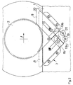
- a holding arm 1 is provided on the outside of the side machine stand of the rotary printing press, which can be pivoted from a vertical rest position into a horizontal working position. In the horizontal position of the holding arms, the unloading or loading of a pressure cylinder is possible, the two hubs 2 being able to be rolled on the horizontal arms 1 in both directions of the arrow (f).
- each arm 1 is provided on the outside with a device designated as a whole by 3.
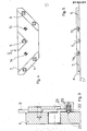
- the device 3 consists essentially of a plate 4 which is fastened to the corresponding holding arm 1 with the aid of screws 5.
- the plate On the side facing the arm 1, the plate has inner mills 6 and 7, which are arranged V-shaped.
- the guides 6 and 7 move freely in the direction of the arrows (g) strips 8 and 9, which protrude over the rolling plane 10 of the corresponding holding arm 1 in the extended position, whereby a V-shaped seat is formed, which is identified by 11 and is suitable to fix the corresponding hub 2 of the pressure cylinder in its precisely defined position in order to enable the assembly or disassembly of the corresponding ball bearing which is assigned to the corresponding hub 2.
- the strips 8 and 9 advantageously have window-like elongated holes 12 and 13 which run in the direction of the longitudinal axis of the strips 8 and 9. These elongated holes 12 and 13 form guide slots with which guide rods 14 and 15 are connected.
- the guide pins 14 and 15 are advantageously arranged directly on the base of the cutouts 6 and 7 of the plate 4 or on the holding arms'.
- the upper ends 8a and 9a or strips 8 and 9 are cut off in such a way that they are aligned parallel to the rolling surface 10 of the corresponding holding arm 1, whereas the lower ends 8b and 9b of the strips 8 and 9 are separated such that they are on the underside of the Plate 4 delimit a space 16.
- This space 16 receives a positioning and drive device, which is designated overall by 17.
- the device 17 essentially consists of a pivot pin 18 which is connected eccentrically to a plate 19 which has a semicircular shape.
- the underside of the semicircular plate 19 is connected to an actuating handle 20, and the ends 19 a and 19 b of the plate, which lie diametrically opposite one another, are in contact with the ends 8 b and 9 b of the strips 8 and 9.
- the device 17 is arranged to be freely movable in the chamber 16 and is held in place by the plate labeled 4.
- a spring 21 is arranged in the interior of the actuating handle 20, which acts on a positioning ball 22, which can snap into reference and positioning bores 23 which are introduced into the holding arm 1.
- the possibility of the device to perform a swing movement is shown by the double arrow (h).
- Fig. 1 the device 3 is shown with extended strips 8 and 9, whereby the hub 2 of the pressure cylinder is received in a precisely defined position in the seat 11.
- the pressure cylinder If the pressure cylinder is to be unloaded, for example, its hubs 2 roll on the surface 10 of the left and right holding arms 1 and run in the example described on the abraded ends of the bar, which is, for example, in the extended position, as is shown by dash-and-dot lines .
- the force exerted by the hub on the end of the last causes the last to be displaced downward into the position shown in full lines and is thus located with the end 8a below the rolling plane 10.
- the hub 2 can move freely in Carry out in the direction of the arrow (F).
- the bar 8 When the bar 8 is shifted downwards, its end 8b acts on the end 19a of the semicircular actuating part 19, whereby this is rotated from its position shown in broken lines to the position shown in solid lines.
- the bar 9 is moved into the maximally extended position via the end pieces 19b and any further rolling movement of the hub 2 in the direction of the arrow (f) is prevented.
- the actuating disc 9 is rotated again into its central position, as shown by dash-and-dot lines, and it is caused that the bar 8 is moved out of the position shown with dash-and-dot lines.
- the hub 2 is finally blocked in the desired position. Movement to the left is thus prevented, and the position assumed is suitable for the assembly or disassembly of the ball bearing on or from the hub 2.
Landscapes
- Engineering & Computer Science (AREA)
- Mechanical Engineering (AREA)
- Rotary Presses (AREA)
- Soil Working Implements (AREA)
- Reduction Rolling/Reduction Stand/Operation Of Reduction Machine (AREA)
- Supply, Installation And Extraction Of Printed Sheets Or Plates (AREA)
- Discharging, Photosensitive Material Shape In Electrophotography (AREA)
Priority Applications (1)
| Application Number | Priority Date | Filing Date | Title |
|---|---|---|---|
| AT86103157T ATE60002T1 (de) | 1985-03-27 | 1986-03-09 | Vorrichtung zum auswechseln eines druckzylinders fuer eine rotationsdruckmaschine. |
Applications Claiming Priority (2)
| Application Number | Priority Date | Filing Date | Title |
|---|---|---|---|
| IT20094/85A IT1184219B (it) | 1985-03-27 | 1985-03-27 | Dispositivo per la sostiatuzione di un cilindro di stampa,asservito ad una macchina rotativa |
| IT2009485 | 1985-03-27 |
Publications (3)
| Publication Number | Publication Date |
|---|---|
| EP0196501A2 true EP0196501A2 (fr) | 1986-10-08 |
| EP0196501A3 EP0196501A3 (en) | 1988-07-27 |
| EP0196501B1 EP0196501B1 (fr) | 1991-01-16 |
Family
ID=11163750
Family Applications (1)
| Application Number | Title | Priority Date | Filing Date |
|---|---|---|---|
| EP86103157A Expired - Lifetime EP0196501B1 (fr) | 1985-03-27 | 1986-03-09 | Dispositif pour échanger un cylindre d'impression dans une rotative |
Country Status (6)
| Country | Link |
|---|---|
| US (1) | US4791867A (fr) |
| EP (1) | EP0196501B1 (fr) |
| JP (1) | JPS61268447A (fr) |
| AT (1) | ATE60002T1 (fr) |
| DE (1) | DE3676845D1 (fr) |
| IT (1) | IT1184219B (fr) |
Cited By (2)
| Publication number | Priority date | Publication date | Assignee | Title |
|---|---|---|---|---|
| EP1066963A1 (fr) * | 1999-07-09 | 2001-01-10 | Gallus Ferd. Rüesch Ag | Mécanisme pour régler un espacement pour les outils dans des groupes imprimants |
| EP1092536A1 (fr) * | 1999-10-11 | 2001-04-18 | Gi Due S.r.l. | Unité d'impression avec cylindre d'impression à enlevement et blocage simplifiés |
Families Citing this family (4)
| Publication number | Priority date | Publication date | Assignee | Title |
|---|---|---|---|---|
| JPS63180231U (fr) * | 1987-05-13 | 1988-11-21 | ||
| DE4001736A1 (de) * | 1990-01-22 | 1991-07-25 | Windmoeller & Hoelscher | Lagerhalterung fuer auf wellenzapfen aufgesetzte lager |
| CN104723657A (zh) * | 2013-12-24 | 2015-06-24 | 上海艾骏机械有限公司 | 一种可快速驱动的柔版印刷单元 |
| EP3199345B1 (fr) * | 2016-01-29 | 2018-11-14 | Comexi Group Industries, S.A.U | Installation d'impression et procédé pour agencement de manchons dans ladite installation d'impression |
Family Cites Families (14)
| Publication number | Priority date | Publication date | Assignee | Title |
|---|---|---|---|---|
| US2204352A (en) * | 1938-05-25 | 1940-06-11 | Ingersoll Rand Co | Centralizer for drill steels |
| US2365683A (en) * | 1941-09-18 | 1944-12-26 | Sullivan Machinery Co | Rock drill |
| US2585325A (en) * | 1948-12-21 | 1952-02-12 | Alico Inc | Inking roller removal truck for newspaper printing presses |
| US2650648A (en) * | 1952-08-13 | 1953-09-01 | American Seating Co | Chair structure |
| US2792781A (en) * | 1953-05-14 | 1957-05-21 | Druckmaschinenwerk Victoria Ve | Cylinder change mechanism for rotary sheet printing presses |
| FR1269425A (fr) * | 1960-08-13 | 1961-08-11 | Miehle Goss Dexter Inc | Appareil permettant le changement des cylindres dans les presses à imprimer |
| US3557689A (en) * | 1968-04-10 | 1971-01-26 | United States Steel Corp | Apparatus for marking a coil of strip |
| DE2314523C3 (de) * | 1973-03-23 | 1981-10-01 | Albert-Frankenthal Ag, 6710 Frankenthal | Vorrichtung zum Auswechseln des Formzylinders an Tiefdruckmaschinen |
| US3986454A (en) * | 1973-07-09 | 1976-10-19 | Granger Wallace H | Multi-purpose side frames for rotary printing press |
| US4076338A (en) * | 1976-04-30 | 1978-02-28 | Gardner-Denver Company | Castering roller for a drill pipe guide bushing |
| DE2632455C3 (de) * | 1976-07-19 | 1979-05-23 | Windmoeller & Hoelscher, 4540 Lengerich | Vorrichtung zum Ein- und Ausfahren des Farbwerkes und des Formzylinders einer Rotations-Tiefdruckmaschine |
| US4076337A (en) * | 1976-09-22 | 1978-02-28 | Ray Childress | Drill steel holder |
| FI65123C (fi) * | 1980-08-25 | 1984-03-12 | Tampella Oy Ab | Borrstoed |
| DE3440895C2 (de) * | 1984-11-09 | 1987-01-22 | M.A.N.- Roland Druckmaschinen AG, 6050 Offenbach | Farbwerk einer Rotationsdruckmaschine, insbesondere Offsetdruckmaschine |
-
1985
- 1985-03-27 IT IT20094/85A patent/IT1184219B/it active
-
1986
- 1986-03-09 AT AT86103157T patent/ATE60002T1/de not_active IP Right Cessation
- 1986-03-09 EP EP86103157A patent/EP0196501B1/fr not_active Expired - Lifetime
- 1986-03-09 DE DE8686103157T patent/DE3676845D1/de not_active Expired - Fee Related
- 1986-03-27 JP JP61067415A patent/JPS61268447A/ja active Granted
- 1986-03-27 US US06/844,862 patent/US4791867A/en not_active Expired - Fee Related
Cited By (5)
| Publication number | Priority date | Publication date | Assignee | Title |
|---|---|---|---|---|
| EP1066963A1 (fr) * | 1999-07-09 | 2001-01-10 | Gallus Ferd. Rüesch Ag | Mécanisme pour régler un espacement pour les outils dans des groupes imprimants |
| WO2001003928A1 (fr) * | 1999-07-09 | 2001-01-18 | Gallus Ferd. Rüesch AG | Dispositif de reglage d'ecartement pour les outils de machines d'impression |
| US6684779B1 (en) | 1999-07-09 | 2004-02-03 | Gallus Ferd, Ruesch Ag | Device for adjusting the distance between tools in printing machinery |
| EP1092536A1 (fr) * | 1999-10-11 | 2001-04-18 | Gi Due S.r.l. | Unité d'impression avec cylindre d'impression à enlevement et blocage simplifiés |
| US6408756B1 (en) | 1999-10-11 | 2002-06-25 | Gi Due S.R.L. | Printing unit with printing cylinder having simplified removal and locking |
Also Published As
| Publication number | Publication date |
|---|---|
| US4791867A (en) | 1988-12-20 |
| ATE60002T1 (de) | 1991-02-15 |
| IT1184219B (it) | 1987-10-22 |
| JPS61268447A (ja) | 1986-11-27 |
| EP0196501B1 (fr) | 1991-01-16 |
| DE3676845D1 (de) | 1991-02-21 |
| JPH0453179B2 (fr) | 1992-08-25 |
| IT8520094A0 (it) | 1985-03-27 |
| EP0196501A3 (en) | 1988-07-27 |
Similar Documents
| Publication | Publication Date | Title |
|---|---|---|
| DE2840408C2 (de) | Vorrichtung zur Ermittlung einer relativen Beweglichkeit zwischen Teilen des Fahrwerks oder der Lenkung bei einem Fahrzeug | |
| EP1122205A1 (fr) | Plate-forme de levage à ciseaux | |
| DE3533303C2 (fr) | ||
| DD282422A5 (de) | Aufspannvorrichtung | |
| DE69906649T2 (de) | Verfahren und Vorrichtung zum Brechen einer Pleuelstange | |
| CH676945A5 (fr) | ||
| DE3517602A1 (de) | Spannvorrichtung fuer gesenke | |
| DE1479547B2 (de) | Vorrichtung zum gleichzeitigen Entfernen überflüssiger· Abfallabschnitte von mehreren fertig geformten Kunststoffteilen, insbesondere von nach dem Blasverfahren hergestellten Hohlkörpern | |
| DE4337902A1 (de) | Stanze für Bahnmaterial | |
| DE2456303C2 (de) | Kantenbiegemaschine für metallene Druckplatten | |
| DE3007261C2 (de) | Vorrichtung zum Halten von Werkstücken mit einer Bohrung | |
| DE3881748T2 (de) | Bügelpresse für Kleider. | |
| EP0196501A2 (fr) | Dispositif pour échanger un cylindre d'impression dans une rotative | |
| DE1634842A1 (de) | Planierfahrzeug | |
| DE3938477C2 (fr) | ||
| DE2900347A1 (de) | Reifenwechselvorrichtung | |
| DE2852610C2 (de) | Reifenpresse | |
| DE2417631C3 (de) | Vorrichtung zum Herstellen von dornartigen Vorsprängen an der Oberfläche eines Werkstücks | |
| DE3120828C2 (de) | Hydraulische Abkant- oder Biegepresse | |
| DE2224875B2 (de) | Vorrichtung zum Belasten und Trennen der Walzen eines der Bearbeitung von Bahnen, insbesondere von Papierbahnen, dienenden Walzensatzes | |
| DE9204888U1 (de) | Selbstzentrierende Gruppe | |
| DE3936048A1 (de) | Verfahren zum positionieren von kalanderwalzen sowie kalander zur ausfuehrung des verfahrens | |
| DE3022922A1 (de) | Blechschere | |
| AT352503B (de) | Vorrichtung zum entgraten beim widerstands- stumpfschweissen von schienen | |
| DE3446889C2 (fr) |
Legal Events
| Date | Code | Title | Description |
|---|---|---|---|
| PUAI | Public reference made under article 153(3) epc to a published international application that has entered the european phase |
Free format text: ORIGINAL CODE: 0009012 |
|
| AK | Designated contracting states |
Kind code of ref document: A2 Designated state(s): AT BE CH DE FR GB IT LI LU NL SE |
|
| PUAL | Search report despatched |
Free format text: ORIGINAL CODE: 0009013 |
|
| AK | Designated contracting states |
Kind code of ref document: A3 Designated state(s): AT BE CH DE FR GB IT LI LU NL SE |
|
| 17P | Request for examination filed |
Effective date: 19881005 |
|
| 17Q | First examination report despatched |
Effective date: 19900322 |
|
| GRAA | (expected) grant |
Free format text: ORIGINAL CODE: 0009210 |
|
| AK | Designated contracting states |
Kind code of ref document: B1 Designated state(s): AT BE CH DE FR GB IT LI LU NL SE |
|
| PG25 | Lapsed in a contracting state [announced via postgrant information from national office to epo] |
Ref country code: IT Free format text: LAPSE BECAUSE OF FAILURE TO SUBMIT A TRANSLATION OF THE DESCRIPTION OR TO PAY THE FEE WITHIN THE PRE;WARNING: LAPSES OF ITALIAN PATENTS WITH EFFECTIVE DATE BEFORE 2007 MAY HAVE OCCURRED AT ANY TIME BEFORE 2007. THE CORRECT EFFECTIVE DATE MAY BE DIFFERENT FROM THE ONE RECORDED.SCRIBED TIME-LIMIT Effective date: 19910116 Ref country code: GB Effective date: 19910116 Ref country code: FR Effective date: 19910116 Ref country code: NL Effective date: 19910116 Ref country code: BE Effective date: 19910116 Ref country code: SE Effective date: 19910116 |
|
| REF | Corresponds to: |
Ref document number: 60002 Country of ref document: AT Date of ref document: 19910215 Kind code of ref document: T |
|
| REF | Corresponds to: |
Ref document number: 3676845 Country of ref document: DE Date of ref document: 19910221 |
|
| PG25 | Lapsed in a contracting state [announced via postgrant information from national office to epo] |
Ref country code: AT Effective date: 19910309 |
|
| PG25 | Lapsed in a contracting state [announced via postgrant information from national office to epo] |
Ref country code: LI Effective date: 19910331 Ref country code: CH Effective date: 19910331 Ref country code: LU Free format text: LAPSE BECAUSE OF NON-PAYMENT OF DUE FEES Effective date: 19910331 |
|
| EN | Fr: translation not filed | ||
| NLV1 | Nl: lapsed or annulled due to failure to fulfill the requirements of art. 29p and 29m of the patents act | ||
| GBV | Gb: ep patent (uk) treated as always having been void in accordance with gb section 77(7)/1977 [no translation filed] | ||
| PLBE | No opposition filed within time limit |
Free format text: ORIGINAL CODE: 0009261 |
|
| STAA | Information on the status of an ep patent application or granted ep patent |
Free format text: STATUS: NO OPPOSITION FILED WITHIN TIME LIMIT |
|
| REG | Reference to a national code |
Ref country code: CH Ref legal event code: PL |
|
| 26N | No opposition filed | ||
| PGFP | Annual fee paid to national office [announced via postgrant information from national office to epo] |
Ref country code: DE Payment date: 19930423 Year of fee payment: 8 |
|
| PG25 | Lapsed in a contracting state [announced via postgrant information from national office to epo] |
Ref country code: DE Effective date: 19941201 |