EP0196558A2 - Fragmentation body for grenades - Google Patents
Fragmentation body for grenades Download PDFInfo
- Publication number
- EP0196558A2 EP0196558A2 EP86103781A EP86103781A EP0196558A2 EP 0196558 A2 EP0196558 A2 EP 0196558A2 EP 86103781 A EP86103781 A EP 86103781A EP 86103781 A EP86103781 A EP 86103781A EP 0196558 A2 EP0196558 A2 EP 0196558A2
- Authority
- EP
- European Patent Office
- Prior art keywords
- splinter
- splinter body
- wall
- thickening
- axis
- Prior art date
- Legal status (The legal status is an assumption and is not a legal conclusion. Google has not performed a legal analysis and makes no representation as to the accuracy of the status listed.)
- Granted
Links
Images
Classifications
-
- F—MECHANICAL ENGINEERING; LIGHTING; HEATING; WEAPONS; BLASTING
- F42—AMMUNITION; BLASTING
- F42B—EXPLOSIVE CHARGES, e.g. FOR BLASTING, FIREWORKS, AMMUNITION
- F42B27/00—Hand grenades
-
- F—MECHANICAL ENGINEERING; LIGHTING; HEATING; WEAPONS; BLASTING
- F42—AMMUNITION; BLASTING
- F42B—EXPLOSIVE CHARGES, e.g. FOR BLASTING, FIREWORKS, AMMUNITION
- F42B12/00—Projectiles, missiles or mines characterised by the warhead, the intended effect, or the material
- F42B12/02—Projectiles, missiles or mines characterised by the warhead, the intended effect, or the material characterised by the warhead or the intended effect
- F42B12/20—Projectiles, missiles or mines characterised by the warhead, the intended effect, or the material characterised by the warhead or the intended effect of high-explosive type
-
- F—MECHANICAL ENGINEERING; LIGHTING; HEATING; WEAPONS; BLASTING
- F42—AMMUNITION; BLASTING
- F42B—EXPLOSIVE CHARGES, e.g. FOR BLASTING, FIREWORKS, AMMUNITION
- F42B12/00—Projectiles, missiles or mines characterised by the warhead, the intended effect, or the material
- F42B12/02—Projectiles, missiles or mines characterised by the warhead, the intended effect, or the material characterised by the warhead or the intended effect
- F42B12/20—Projectiles, missiles or mines characterised by the warhead, the intended effect, or the material characterised by the warhead or the intended effect of high-explosive type
- F42B12/22—Projectiles, missiles or mines characterised by the warhead, the intended effect, or the material characterised by the warhead or the intended effect of high-explosive type with fragmentation-hull construction
- F42B12/32—Projectiles, missiles or mines characterised by the warhead, the intended effect, or the material characterised by the warhead or the intended effect of high-explosive type with fragmentation-hull construction the hull or case comprising a plurality of discrete bodies, e.g. steel balls, embedded therein or disposed around the explosive charge
Definitions
- the invention relates to a fragmentation body for grenades, in particular hand grenades, consisting of a hollow body, the wall of which consists of metal particles embedded in plastic and which has a different shape from the spherical shape, in the axis of which the fragmentation body has at least one opening, the wall of the splinter body has an axially symmetrical thickening with an increased accumulation of metal particles compared to the adjacent wall regions of the splinter body
- the spherical shape of the splinter body with a detonator arranged in the center of the ball would in itself be ideal.
- the detonation wave emanating from the detonator reaches all points of the inner spherical surface of the splinter body at the same moment, so that the entire splinter shell is also disassembled at the same time - especially with hand grenades - for reasons of dimensioning.
- the required number of fragments and the amount of explosives required would result in a relatively large ball as a splinter body, the handiness of such a hand grenade would be impaired however, the splinter distribution is irregular, ie in different directions based on the three-dimensional axis system of the hand grenade.
- Splinter bodies for hand grenades have become known which have an inward thickening approximately in the central region or somewhat above the middle of the side wall, as a result of which the interior of the hand grenade is divided into two subspaces, a usually smaller upper and a larger lower one (AT- A-357 90 4 , AT-A-368 280).
- This measure was intended to influence the propagation of the detonation wave inside the hand grenade in the sense of a uniform spreading of the fragments or metal particles.
- this effect has not shown sufficient effect in practice.
- the thickening of the wall of the splinter body is formed in the transition region between the bottom surface and the side surface, and / or between the shoulder surface and the side surface
- the bottom surface is the inner surface of the splinter body opposite the opening for the igniter.
- the shoulder surface is the inner surface of the splinter body surrounding the opening for the igniter
- the thickening of the wall of the splinter body according to the invention is advantageously directed into the interior of the hand grenade, in the form of an inward curvature of the inner wall, since an outward thickening would have a rather unfavorable effect on the outer shape of the hand grenade.
- an increased accumulation of metal particles in the wall of the splinter body in the transition region between the bottom surface and the side surface of the splinter body is important, because a noticeable defect in splinter penetration was perceived in the splinter scattering sector corresponding to this region.
- a similar fragmentation defect can also occur in the fragmentation sector assigned to the wall area of the fragment body between the shoulder surface and the side surface.
- the measure according to the invention is particularly effective in the case of a grenade or hand grenade in which the detonator or detonator center is at least approximately in the region of the center of the splinter body, but above all for a detonator which extends along the axis of the splinter body and with Distance above the lower thickening or (if there is also an upper thickening) ends at a distance below the upper thickening of the splinter body
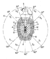
- the invention is explained in more detail with reference to the drawing using an exemplary embodiment.
- the drawing shows a hand grenade, partly in vertical section
- the hand grenade shown in the drawing has a hand grenade body 1, which consists of an inner fragment body 2 designed as a hollow body and an outer housing shell 3.
- the outer housing shell 3 is made of tough-elastic plastic, for example polyethylene, and has a neck-shaped extension 4 with an external thread .
- the wall of the splinter body 2 consists of metal particles embedded in plastic in the form of steel balls. The metal particles are arranged in a tight packing.
- the plastic connecting the metal particles can be made of polystyrene, for example.
- a detonator head 5 is screwed onto the hand grenade body and carries the usual functional elements, such as bats, safety clips and detonator tubes 6.
- the wall of the splinter body 2 has an axially symmetrical thickening 10 in the form of an inward bulge in the transition region between the bottom surface 8 and the side surface 9. In this thickening 10 there is an increased accumulation of metal particles compared to the adjacent wall areas of the splinter body 2.
- an axially symmetrical thickening 11 in the form of an inward bulge may also be present in the transition region between the shoulder surface 12 and the side surface 9 of the splinter body.
- the drawing also shows a spherical surface K which is concentric with the center M of the splinter body
- the axis of the spherical surface K which coincides with the axis A of the splinter body and points from the center M in the direction of the igniter opening is defined as its zero degree axis.
- the thickening 10 of the wall of the splinter body is in the illustrated embodiment between the spherical sectors S, 135 ° and S 2 of 160 °.
- the possible upper thickening 11 of the wall of the splinter body is between the spherical sector S 3 of 20 ° and S4 of 45 °.
- the center point M of the splinter body is the bisection point of the axial extent (external dimension) of the splitter body 2.
- the detonator 13 which is arranged in the lower part of the ignition tube 6 and consists, for example, of four partial charges, is arranged such that its center is at the center M of the fragment body.
- the detonator extending in the direction of the axis A of the splinter body ends at a distance above the thickening 10 and above at a distance below the thickening 11 (if there is one).
- the illustrated embodiment shows an essentially egg-shaped splinter body.
- the measure according to the invention can advantageously but also in other "stretched" forms of fragmentation shell Einset - zen, such as Splitterkörpem in the form of an ellipsoid, a cylinder, possibly with up and molded bottom cone or hemispheres, etc..
- the invention is also not limited to hand grenades, although it is of particular importance in this area of application
Landscapes
- Engineering & Computer Science (AREA)
- General Engineering & Computer Science (AREA)
- Chemical & Material Sciences (AREA)
- Combustion & Propulsion (AREA)
- Prostheses (AREA)
- Aiming, Guidance, Guns With A Light Source, Armor, Camouflage, And Targets (AREA)
- Manipulator (AREA)
Abstract
Splitterkörper für Granaten, insbesondere Handgranaten, bestehend aus einem Hohlkörper, dessen Wandung aus in Kunststoff eingebetteten Metallpartikeln besteht und der eine von der Kugelform abweichende gestreckte Gestalt, z.B. Eiform, aufweist Die Wand des Splitterkörpers (2) weist im Übergangsbereich zwischen der Bodenfläche (8) und der Seitenfläche (9), und/oder zwischen der Schulterfläche (12) und der Seitenfläche (9) eine achssymmetrische Verdickung - (10,11) mit einer gegenüber den benachbarten Wandbereichen des Splitterkörpers (2) erhöhten Anhäufung von Metallpartikeln auf.Splinter body for grenades, in particular hand grenades, consisting of a hollow body, the wall of which consists of plastic particles embedded in plastic and which has an elongated shape deviating from the spherical shape, e.g. Egg-shaped, the wall of the splinter body (2) has an axially symmetrical thickening in the transition area between the bottom surface (8) and the side surface (9) and / or between the shoulder surface (12) and the side surface (9) - (10, 11) with an increased accumulation of metal particles compared to the adjacent wall areas of the splinter body (2).
Description
Die Erfindung bezieht sich auf einen Splitterkörper für Granaten, insbesondere Handgranaten, bestehend aus einem Hohlkörper, dessen Wandung aus in Kunststoff eingebetteten Metallpartikeln besteht und der eine von der Kugelform abweichende gestreckte Gestalt aufweist, in deren Achse der Splitterkörper mindestens eine Öffnung besitzt, wobei die Wand des Splitterkörpers eine achssymmetrische Verdickung mit einer gegenüber den benachbarten Wandbereichen des Splitterkörpers erhöhten Anhäufung von Metallpartikeln aufweistThe invention relates to a fragmentation body for grenades, in particular hand grenades, consisting of a hollow body, the wall of which consists of metal particles embedded in plastic and which has a different shape from the spherical shape, in the axis of which the fragmentation body has at least one opening, the wall of the splinter body has an axially symmetrical thickening with an increased accumulation of metal particles compared to the adjacent wall regions of the splinter body
Um bei einer Granate, insbesondere Handgranate, eine möglichst gleichmäßige Splitterverteilung zu erreichen, wäre an sich die Kugelform des Splitterkörpers mit einem im Zentrum der Kugel angeordneten Detonator ideal. In diesem Falle erreicht nämlich die vom Detonator ausgehende Detonationswelle alle Punkte der inneren Kugelfläche des Splitterkörpers im gleichen Augenblick, sodaß auch die Zerlegung des gesamten Splittermantels gleichzeitig erfolgt Kugelförmige Splitterkörper lassen sich jedoch in der Praxis nicht immer realisieren, und zwar einerseits aus ballistischen Gründen, andererseits -insbesondere bei Handgranaten - aus Gründen der Dimensionierung. Wenn nämlich die erforderliche Splitteranzahl und die benötigte Sprengstoffmenge eine relativ große Kugel als Splitterkörper ergäbe, wäre die Handlichkeit einer solchen Handgranate beeinträchtigt Es werden daher Handgranaten für größere Splitter-und Detonationsleistungen üblicherweise nicht mit kugelförmigen, sondern mit eiförmigen oder sonstwie gestreckten Splitterkörpem ausgebildet Bei diesen Handgranaten ist jedoch die Splitterverteilung unregelmäßig, d.h. in verschiedenen Richtungen bezogen auf das dreidimensionale Achssystem der Handgranate unterschiedlich.In order to achieve the most uniform possible splinter distribution in a grenade, in particular a hand grenade, the spherical shape of the splinter body with a detonator arranged in the center of the ball would in itself be ideal. In this case, the detonation wave emanating from the detonator reaches all points of the inner spherical surface of the splinter body at the same moment, so that the entire splinter shell is also disassembled at the same time - especially with hand grenades - for reasons of dimensioning. If the required number of fragments and the amount of explosives required would result in a relatively large ball as a splinter body, the handiness of such a hand grenade would be impaired however, the splinter distribution is irregular, ie in different directions based on the three-dimensional axis system of the hand grenade.
Es sind Splitterkörper für Handgranaten bekannt geworden, die etwa im mittleren Bereich oder etwas über der Mitte der Seitenwand eine nach innen gerichtete Verdickung aufweisen, wodurch der Innenraum der Handgranate in zwei Teilräume, einen meist kleineren oberen und einen größeren unteren, unterteilt wird (AT-A-357 904, AT-A-368 280). Mit dieser Maßnahme sollte die Ausbreitung der Detonationswelle im inneren der Handgranate im Sinne einer gleichmäßigen Äusstreuung der Splitter bzw. Metallpartikel beeinflußt werden. Dieser Effekt hat jedoch in der Praxis keine ausreichende Wirkung gezeigt.Splinter bodies for hand grenades have become known which have an inward thickening approximately in the central region or somewhat above the middle of the side wall, as a result of which the interior of the hand grenade is divided into two subspaces, a usually smaller upper and a larger lower one (AT- A-357 90 4 , AT-A-368 280). This measure was intended to influence the propagation of the detonation wave inside the hand grenade in the sense of a uniform spreading of the fragments or metal particles. However, this effect has not shown sufficient effect in practice.
Es blieb daher nach wie vor die Aufgabe ungelöst, einen Splitterkörper für eine Granate, insbesondere Handgranate zu schaffen, der -obgleich nicht von kugelförmiger Gestalt -ähnlich wie ein kugelförmiger Splitterkörper eine möglichst gleichmäßige Splitterverteilung garantiert.The task therefore still remained unsolved to create a splinter body for a grenade, in particular a hand grenade, which - although not of a spherical shape - similar to a spherical splinter body, guarantees the most uniform possible splinter distribution.
Die Lösung dieser Aufgabe besteht erfindungsgemäß darin, daß die Verdickung der Wand des Splitterkörpers im Übergangsbereich zwischen der Bodenfläche und der Seitenfläche, und/oder zwischen der Schulterfläche und der Seitenfläche ausgebildet istThe solution to this problem is, according to the invention, that the thickening of the wall of the splinter body is formed in the transition region between the bottom surface and the side surface, and / or between the shoulder surface and the side surface
Die Bodenfläche ist die der Öffnung für den Zünder gegenüberliegende Innenfläche des Splitterkörpers. Als Schulterfläche wird die die Öffnung für den Zünder umgebende Innenfläche des Splitterkörpers bezeichnetThe bottom surface is the inner surface of the splinter body opposite the opening for the igniter. The shoulder surface is the inner surface of the splinter body surrounding the opening for the igniter
Es hat sich herausgestellt, daß mit Hilfe der erfindungsgemäßen Maßnahme im Vergleich zu einer Handgranate mit einem Splitterkörper von eiförmiger Gestalt in bekannter Ausführung eine gleichmäßigere Verteilung von wirksamen Splittern, d.h. eine gleichmäßigere Verteilung der Splitterdurchschläge durch eine Prüfwand,erzielt wird, die die zu prüfende Handgranate in einem bestimmten Abstand zylinderförmig umgibtIt has been found that with the aid of the measure according to the invention, in comparison with a hand grenade with a splinter body of egg-shaped shape in a known design, a more uniform distribution of effective splinters, i.e. a more uniform distribution of the chip penetration is achieved by a test wall, which surrounds the hand grenade to be tested at a certain distance in a cylindrical shape
Die erfindungsgemäße Verdickung der Wand des Splitterkörpers wird vorteilhafterweise in das Innere der Handgranate gerichtet, und zwar in Form einer nach innen gerichteten Auswölbung der Innenwand, da eine nach außen gerichtete Verdickung die Außenform der Handgranate eher ungünstig beeinflussen würde.The thickening of the wall of the splinter body according to the invention is advantageously directed into the interior of the hand grenade, in the form of an inward curvature of the inner wall, since an outward thickening would have a rather unfavorable effect on the outer shape of the hand grenade.
Es hat sich herausgestellt, daß ein besonders günstiger Effekt im Sinne einer Vergleichmäßigung des Splitterdurchschlagbildes dann erzielt wird, wenn die Verdickung der Wand des Splitterkörpers,bezogen auf eine zum Mittelpunkt des Splitterkörpers konzentrische Kugelfläche, im Bereich zwischen den Kugelsektoren von 130° und 165°, vorzugsweise von 135° und 160° liegt, wobei die Nullgradachse mit der Achse des Splitterkörpers zusammenfällt und zur Öffnung des Splitterkörpers weistIt has been found that a particularly favorable effect in terms of an evenening of the splinter penetration pattern is achieved if the thickening of the wall of the splinter body, based on a spherical surface concentric to the center of the splinter body, in the area between the spherical sectors of 130 ° and 165 °, is preferably 135 ° and 160 °, the zero degree axis coinciding with the axis of the splinter body and pointing to the opening of the splitter body
Wichtig ist vor allem eine erhöhte Anhäufung von Metallpartikeln in der Wand des Splitterkörpers im Übergangsbereich zwischen der Bodenfläche und der Seitenfläche des Splitterkörpers, weil gerade in dem diesem Bereich entsprechenden Splitterstreusektor ein auffälliger Defekt an Splitterdurchschlägen wahrgenommen wurde. Ein ähnlicher Splitterdurchschalgsdefekt kann aber auch in der dem Wandbereich des Splitterkörpers zwischen Schulterfläche und Seitenfläche zugeordneten Splitterstreusektor auftreten. Es ist daher gegebenenfalls vorteilhaft, im Übergangsbereich zwischen Schulterfläche und Seitenfläche des Splitterkörpers eine Verdickung mit erhöhter Anhäufung von Metallpartikeln vorzusehen, und zwar, bezogen auf eine zum Mittelpunkt des Splitterkörpers konzentrische Kugelfläche, zweckmäßig im Bereich zwischen den Kugelsektoren von 15° und 50°, vorzugsweise von 20° und 45°.Above all, an increased accumulation of metal particles in the wall of the splinter body in the transition region between the bottom surface and the side surface of the splinter body is important, because a noticeable defect in splinter penetration was perceived in the splinter scattering sector corresponding to this region. A similar fragmentation defect can also occur in the fragmentation sector assigned to the wall area of the fragment body between the shoulder surface and the side surface. It may therefore be advantageous to provide a thickening with an increased accumulation of metal particles in the transition area between the shoulder surface and the side surface of the splinter body, with reference to a spherical surface concentric to the center of the splinter body, expediently in the region between the spherical sectors of 15 ° and 50 °, preferably of 20 ° and 45 °.
Die erfindungsgemäße Maßnahme ist insbesondere wirksam bei einer Granate bzw. Handgranate, bei der sich der Detonator bzw. das Detonatorzentrum wenigstens annähernd im Bereich des Mittelpunktes des Splitterkörpers befindet, vor allem aber auch für einen Detonator, der sich längs der Achse des Splitterkörpers erstreckt und mit Abstand oberhalb der unteren Verdickung bzw. (falls auch eine obere Verdickung vorhanden ist) mit Abstand unterhalb der oberen Verdickung des Splitterkörpers endetThe measure according to the invention is particularly effective in the case of a grenade or hand grenade in which the detonator or detonator center is at least approximately in the region of the center of the splinter body, but above all for a detonator which extends along the axis of the splinter body and with Distance above the lower thickening or (if there is also an upper thickening) ends at a distance below the upper thickening of the splinter body
Die Erfindung wird anhand der Zeichnung durch ein Ausführungsbeispiel näher erläutert Die Zeichnung zeigt eine Handgranate, teilweise im VertikalschnittThe invention is explained in more detail with reference to the drawing using an exemplary embodiment. The drawing shows a hand grenade, partly in vertical section
Die in der Zeichnung dargestellte Handgranate weist einen Handgranatenkörper 1 auf, der aus einem inneren, als Hohlkörper ausgebildeten Splitterkörper 2 und einem äußeren Gehäusemantel 3 besteht Der äußere Gehäusemantel 3 ist aus zähelastischem Kunststoff, z.B. Polyäthylen, gefertigt und weist einen halsförmigen Ansatz 4 mit Außengewinde auf. Die Wand des Splitterkörpers 2 besteht aus in Kunststoff eingebetteten Metallpartikeln in Form von Stahlkugeln. Die Metallpartikel sind in dichter Packung angeordnet Der die Metallpartikel verbindende Kunststoff kann beispielsweise aus Polystyrol bestehen.The hand grenade shown in the drawing has a hand grenade body 1, which consists of an
Auf dem Handgranatenkörper ist ein Zünderkopf 5 aufgeschraubt, der die üblichen Funktionselemente, wie Schläger, Sicherungsbügel und Zündröhrchen 6 trägt Das Zündröhrchen 6 ragt durch die zentrale Öffnung des Splitterkörpers 2 in das Innere der Handgranate, und zwar in eine Aussparung des Sprengsatzes 4.A
Die Wand des Splitterkörpers 2 weist im Übergangsbereich zwischen der Bodenfläche 8 und der Seitenfläche 9 eine achssymmetrische Verdickung 10 in Form einer nach innen gerichteten Auswölbung auf. In dieser Verdickung 10 befindet sich eine gegenüber den benachbarten Wandbereichen des Splitterkörpers 2 erhöhte Anhäufung von Metallpartikeln.The wall of the
Gegebenenfalls kann auch im Übergangsbereich zwischen der Schulterfläche 12 und der Seitenfläche 9 des Splitterkörpers eine achssymmetrische Verdickung 11 (in der Zeichnung strichliert angedeutet) in Form einer nach innen gerichteten Auswölbung vorhanden sein.Optionally, an axially symmetrical thickening 11 (indicated by dashed lines in the drawing) in the form of an inward bulge may also be present in the transition region between the
In der Zeichnung ist auch eine zum Mittelpunkt M des Splitterkörpers konzentrische Kugelfläche K dargestelltThe drawing also shows a spherical surface K which is concentric with the center M of the splinter body
Die mit der Achse A des Splitterkörpers zusammenfallende und vom Mittelpunkt M in Richtung zur Zünderöffnung weisende Achse der Kugelfläche K wird als deren Nullgradachse definiert. Die Verdickung 10 der Wand des Splitterkörpers liegt beim dargestellten Ausführungsbeispiel zwischen den Kugelsektoren S, von 135° und S2 von 160°. Die allfällige obere Verdickung 11 der Wand des Splitterkörpers liegt zwischen dem Kugelsektor S3 von 20° und S4 von 45°. Der Mittelpunkt M des Splitterkörpers ist der Halbierungspunkt der axialen Erstreckung (Außenmaß) des Splitterkörpers 2.The axis of the spherical surface K which coincides with the axis A of the splinter body and points from the center M in the direction of the igniter opening is defined as its zero degree axis. The
Der Detonator 13, der im unteren Teil des Zündröhrchens 6 angeordnet ist und beispielsweise aus vier Teilladungen besteht, ist so angeordnet, daß sein Zentrum sich im mittelpunkt M des Splitterkörpers befindet. Der sich in Richtung der Achse A des Splitterkörpers erstreckende Detonator endet unten mit Abstand oberhalb der Verdickung 10 und oben mit Abstand unterhalb der Verdickung 11 (falls eine solche vorhanden ist).The
Das dargestellte Ausführungsbeispiel zeigt einen im wesentlichen eiförmigen Splitterkörper. Die erfindungsgemäße Maßnahme läßt sich mit Vorteil aber auch bei anderen "gestreckten" Formen des Splitterkörpers einset- zen, beispielsweise bei Splitterkörpem in Form eines Ellipsoides, eines Zylinders,gegebenenfalls mit oben und unten angeformten Kegel-oder Halbkugelflächen,u.dgl.The illustrated embodiment shows an essentially egg-shaped splinter body. The measure according to the invention can advantageously but also in other "stretched" forms of fragmentation shell Einset - zen, such as Splitterkörpem in the form of an ellipsoid, a cylinder, possibly with up and molded bottom cone or hemispheres, etc..
Die Erfindung ist auch nicht auf Handgranaten beschränkt, obgleich ihr auf diesem Anwendungsgebiet besondere Bedeutung zukommtThe invention is also not limited to hand grenades, although it is of particular importance in this area of application
Claims (6)
Applications Claiming Priority (2)
| Application Number | Priority Date | Filing Date | Title |
|---|---|---|---|
| AT954/85 | 1985-04-01 | ||
| AT0095485A AT387281B (en) | 1985-04-01 | 1985-04-01 | SPLITTER BODY FOR GRENADES, ESPECIALLY HAND GRENADES |
Publications (3)
| Publication Number | Publication Date |
|---|---|
| EP0196558A2 true EP0196558A2 (en) | 1986-10-08 |
| EP0196558A3 EP0196558A3 (en) | 1987-05-06 |
| EP0196558B1 EP0196558B1 (en) | 1992-08-12 |
Family
ID=3503644
Family Applications (1)
| Application Number | Title | Priority Date | Filing Date |
|---|---|---|---|
| EP86103781A Expired - Lifetime EP0196558B1 (en) | 1985-04-01 | 1986-03-20 | Fragmentation body for grenades |
Country Status (9)
| Country | Link |
|---|---|
| US (1) | US4817532A (en) |
| EP (1) | EP0196558B1 (en) |
| CN (1) | CN86102166A (en) |
| AT (1) | AT387281B (en) |
| DE (1) | DE3686342D1 (en) |
| ES (1) | ES288272Y (en) |
| GR (1) | GR860806B (en) |
| MY (1) | MY101517A (en) |
| ZA (1) | ZA862218B (en) |
Cited By (1)
| Publication number | Priority date | Publication date | Assignee | Title |
|---|---|---|---|---|
| RU2690566C1 (en) * | 2018-12-06 | 2019-06-04 | Игнат Игоревич Иванов | Grenade jacket |
Families Citing this family (13)
| Publication number | Priority date | Publication date | Assignee | Title |
|---|---|---|---|---|
| SG82583A1 (en) * | 1997-04-23 | 2001-08-21 | Diehl Stiftung & Co | Fragmentation body for a fragmentation projectile |
| USD472800S1 (en) | 2002-04-25 | 2003-04-08 | 5 Oaks Creative Development And Design, Inc. | Grenade shaped container for bearings |
| FR2867849B1 (en) * | 2004-03-16 | 2006-07-21 | Catherine Tanguy | FRAGMENTABLE GRENAGE |
| US20070209500A1 (en) * | 2006-03-13 | 2007-09-13 | System Planning Corporation | Method and apparatus for disarming an explosive device |
| US9234730B1 (en) * | 2007-10-22 | 2016-01-12 | Kendrick Cook | Hand grenade |
| US8365670B2 (en) * | 2010-01-25 | 2013-02-05 | Igor Abramov | Dual mode grenade |
| US8671840B2 (en) | 2011-01-28 | 2014-03-18 | The United States Of America As Represented By The Secretary Of The Navy | Flexible fragmentation sleeve |
| US8967049B2 (en) | 2011-01-28 | 2015-03-03 | The United States Of America As Represented By The Secretary Of The Navy | Solid lined fabric and a method for making |
| RU2473043C2 (en) * | 2011-04-19 | 2013-01-20 | Александр Петрович Митянин | Grenade jacket |
| USD685543S1 (en) * | 2012-12-06 | 2013-07-02 | Carson Optical, Inc. | Air blower |
| US9423228B2 (en) * | 2014-07-02 | 2016-08-23 | The United States Of America As Represented By The Scretary Of The Navy | Advanced fragmentation hand grenade |
| US9470495B2 (en) * | 2015-03-20 | 2016-10-18 | Combined Systems, Inc. | Rubber fragmentation grenade |
| US10066915B1 (en) * | 2016-09-21 | 2018-09-04 | The United States Of America As Represented By The Secretary Of The Army | Multi-purpose state changing munition |
Family Cites Families (11)
| Publication number | Priority date | Publication date | Assignee | Title |
|---|---|---|---|---|
| CA587310A (en) * | 1959-11-17 | Olin Mathieson Chemical Corporation | Training grenade | |
| CA617519A (en) * | 1961-04-04 | Leitner Karl | Shell | |
| GB190711880A (en) * | 1907-05-22 | 1907-09-19 | Siegfried Hoffmann | Improved Projectile. |
| US2109479A (en) * | 1937-09-29 | 1938-03-01 | Gibbons Wayne | Grenade and method of making the same |
| US2564751A (en) * | 1945-05-19 | 1951-08-21 | Lawrence H Cook | Grenade |
| NL278102A (en) * | 1961-05-05 | |||
| AT240735B (en) * | 1961-09-06 | 1965-06-10 | Ulbricht Hein Wwe Gmbh | Fragile projectile |
| US3705552A (en) * | 1971-02-08 | 1972-12-12 | Us Army | Pyrotechnic coiled delay cord assembly for hand grenade fuze |
| IT1108788B (en) * | 1978-07-25 | 1985-12-09 | Oregon Ets Patentverwertung | GRENADE |
| AT357904B (en) * | 1978-08-03 | 1980-08-11 | Oregon Ets Patentverwertung | HAND GRENADE |
| AT368280B (en) * | 1980-07-07 | 1982-09-27 | Oregon Ets Patentverwertung | HAND GRENADE |
-
1985
- 1985-04-01 AT AT0095485A patent/AT387281B/en not_active IP Right Cessation
- 1985-07-22 ES ES1985288272U patent/ES288272Y/en not_active Expired
-
1986
- 1986-03-20 EP EP86103781A patent/EP0196558B1/en not_active Expired - Lifetime
- 1986-03-20 DE DE8686103781T patent/DE3686342D1/en not_active Expired - Fee Related
- 1986-03-25 ZA ZA862218A patent/ZA862218B/en unknown
- 1986-03-27 GR GR860806A patent/GR860806B/en unknown
- 1986-03-31 CN CN198686102166A patent/CN86102166A/en active Pending
-
1987
- 1987-09-22 MY MYPI87001835A patent/MY101517A/en unknown
-
1988
- 1988-04-01 US US07/177,870 patent/US4817532A/en not_active Expired - Fee Related
Cited By (1)
| Publication number | Priority date | Publication date | Assignee | Title |
|---|---|---|---|---|
| RU2690566C1 (en) * | 2018-12-06 | 2019-06-04 | Игнат Игоревич Иванов | Grenade jacket |
Also Published As
| Publication number | Publication date |
|---|---|
| CN86102166A (en) | 1987-01-14 |
| US4817532A (en) | 1989-04-04 |
| EP0196558A3 (en) | 1987-05-06 |
| ES288272Y (en) | 1987-04-01 |
| AT387281B (en) | 1988-12-27 |
| ATA95485A (en) | 1988-05-15 |
| DE3686342D1 (en) | 1992-09-17 |
| EP0196558B1 (en) | 1992-08-12 |
| MY101517A (en) | 1991-11-30 |
| ZA862218B (en) | 1986-11-26 |
| GR860806B (en) | 1986-07-21 |
| ES288272U (en) | 1986-07-16 |
Similar Documents
| Publication | Publication Date | Title |
|---|---|---|
| EP0196558A2 (en) | Fragmentation body for grenades | |
| DE2833877C2 (en) | Hand grenade | |
| EP0088999B1 (en) | Projectile with armour-piercing core for fighting a multiple-layer armour | |
| EP0328877A1 (en) | Projectile with a fragmenting shell | |
| AT411935B (en) | FLOOR HOOD | |
| DE2519507A1 (en) | Warhead for attacking aerial targets - with target seeking guidance system and transverse hollow charges aligned on the target | |
| DE10034818B4 (en) | shower | |
| EP0833018A2 (en) | Hinge device | |
| DE4035780A1 (en) | Spring support device with low mass and low resonant frequency - uses symmetrically located spring elements with impact buffer having two common connectors | |
| DE2925435A1 (en) | Spray head for pressurised liq. has opening for insert - with outer axial grooves forming nozzle ducts with wall of opening | |
| AT357904B (en) | HAND GRENADE | |
| EP0686733A1 (en) | Vibration absorber for vibration-endangered structural parts and structures | |
| EP0134498B1 (en) | Cap for mines with a hollow charge | |
| DE102020121948B3 (en) | Wrap-on post for connection to a bobbin of an electromagnetic coil | |
| DE2634322C2 (en) | Practice or blank cartridge with a projectile part made of plastic | |
| DE4102164A1 (en) | Threaded insert for connecting two component parts - has externally threaded outer part and internally threaded inner part | |
| DE3528339A1 (en) | DEVICE FOR INITIATING A BLAST CHARGE | |
| CH675769A5 (en) | Sectored head on detachable sabot - shatters with retainer ring having breakage grooves immediately after release on firing | |
| EP0663320A2 (en) | Lighting unit for vehicle | |
| AT376599B (en) | ARRANGEMENT FOR LIMITING THE RELATIVE ROTATABILITY OF COMPONENTS | |
| DE4445454A1 (en) | Blind rivet with headed rivet stem | |
| AT399207B (en) | Wall anchor | |
| DD228174A1 (en) | SPATIAL LOGIC TOY WITH MOVABLE SINGLE SEGMENTS | |
| DE202017106065U1 (en) | Drill Nail holding system | |
| DE3717629A1 (en) | Vibration damper for skis |
Legal Events
| Date | Code | Title | Description |
|---|---|---|---|
| PUAI | Public reference made under article 153(3) epc to a published international application that has entered the european phase |
Free format text: ORIGINAL CODE: 0009012 |
|
| AK | Designated contracting states |
Kind code of ref document: A2 Designated state(s): BE CH DE FR GB IT LI NL SE |
|
| PUAL | Search report despatched |
Free format text: ORIGINAL CODE: 0009013 |
|
| AK | Designated contracting states |
Kind code of ref document: A3 Designated state(s): BE CH DE FR GB IT LI NL SE |
|
| 17P | Request for examination filed |
Effective date: 19870702 |
|
| 17Q | First examination report despatched |
Effective date: 19881108 |
|
| GRAA | (expected) grant |
Free format text: ORIGINAL CODE: 0009210 |
|
| ITF | It: translation for a ep patent filed | ||
| AK | Designated contracting states |
Kind code of ref document: B1 Designated state(s): BE CH DE FR GB IT LI NL SE |
|
| GBT | Gb: translation of ep patent filed (gb section 77(6)(a)/1977) | ||
| REF | Corresponds to: |
Ref document number: 3686342 Country of ref document: DE Date of ref document: 19920917 |
|
| ET | Fr: translation filed | ||
| PLBE | No opposition filed within time limit |
Free format text: ORIGINAL CODE: 0009261 |
|
| STAA | Information on the status of an ep patent application or granted ep patent |
Free format text: STATUS: NO OPPOSITION FILED WITHIN TIME LIMIT |
|
| 26N | No opposition filed | ||
| EAL | Se: european patent in force in sweden |
Ref document number: 86103781.0 |
|
| PGFP | Annual fee paid to national office [announced via postgrant information from national office to epo] |
Ref country code: CH Payment date: 19960215 Year of fee payment: 11 |
|
| PGFP | Annual fee paid to national office [announced via postgrant information from national office to epo] |
Ref country code: FR Payment date: 19960329 Year of fee payment: 11 |
|
| PGFP | Annual fee paid to national office [announced via postgrant information from national office to epo] |
Ref country code: NL Payment date: 19960331 Year of fee payment: 11 |
|
| PGFP | Annual fee paid to national office [announced via postgrant information from national office to epo] |
Ref country code: BE Payment date: 19960409 Year of fee payment: 11 |
|
| PGFP | Annual fee paid to national office [announced via postgrant information from national office to epo] |
Ref country code: DE Payment date: 19960528 Year of fee payment: 11 |
|
| PG25 | Lapsed in a contracting state [announced via postgrant information from national office to epo] |
Ref country code: LI Effective date: 19970331 Ref country code: CH Effective date: 19970331 Ref country code: BE Effective date: 19970331 |
|
| BERE | Be: lapsed |
Owner name: OREGON ETABLISSEMENT FUR PATENTVERWERTUNG Effective date: 19970331 |
|
| PG25 | Lapsed in a contracting state [announced via postgrant information from national office to epo] |
Ref country code: NL Effective date: 19971001 |
|
| REG | Reference to a national code |
Ref country code: CH Ref legal event code: PL |
|
| PG25 | Lapsed in a contracting state [announced via postgrant information from national office to epo] |
Ref country code: FR Free format text: LAPSE BECAUSE OF NON-PAYMENT OF DUE FEES Effective date: 19971128 |
|
| NLV4 | Nl: lapsed or anulled due to non-payment of the annual fee |
Effective date: 19971001 |
|
| PG25 | Lapsed in a contracting state [announced via postgrant information from national office to epo] |
Ref country code: DE Effective date: 19971202 |
|
| REG | Reference to a national code |
Ref country code: FR Ref legal event code: ST |
|
| PGFP | Annual fee paid to national office [announced via postgrant information from national office to epo] |
Ref country code: GB Payment date: 20000321 Year of fee payment: 15 |
|
| PGFP | Annual fee paid to national office [announced via postgrant information from national office to epo] |
Ref country code: SE Payment date: 20010316 Year of fee payment: 16 |
|
| PG25 | Lapsed in a contracting state [announced via postgrant information from national office to epo] |
Ref country code: GB Free format text: LAPSE BECAUSE OF NON-PAYMENT OF DUE FEES Effective date: 20010320 |
|
| GBPC | Gb: european patent ceased through non-payment of renewal fee |
Effective date: 20010320 |
|
| PG25 | Lapsed in a contracting state [announced via postgrant information from national office to epo] |
Ref country code: SE Free format text: LAPSE BECAUSE OF NON-PAYMENT OF DUE FEES Effective date: 20020321 |
|
| EUG | Se: european patent has lapsed |
Ref document number: 86103781.0 |
|
| PG25 | Lapsed in a contracting state [announced via postgrant information from national office to epo] |
Ref country code: IT Free format text: LAPSE BECAUSE OF NON-PAYMENT OF DUE FEES;WARNING: LAPSES OF ITALIAN PATENTS WITH EFFECTIVE DATE BEFORE 2007 MAY HAVE OCCURRED AT ANY TIME BEFORE 2007. THE CORRECT EFFECTIVE DATE MAY BE DIFFERENT FROM THE ONE RECORDED. Effective date: 20050320 |