EP0196562A2 - Système de régulation pour un chauffage électrique de sauna - Google Patents
Système de régulation pour un chauffage électrique de sauna Download PDFInfo
- Publication number
- EP0196562A2 EP0196562A2 EP86103812A EP86103812A EP0196562A2 EP 0196562 A2 EP0196562 A2 EP 0196562A2 EP 86103812 A EP86103812 A EP 86103812A EP 86103812 A EP86103812 A EP 86103812A EP 0196562 A2 EP0196562 A2 EP 0196562A2
- Authority
- EP
- European Patent Office
- Prior art keywords
- control system
- temperature
- switches
- sauna
- control
- Prior art date
- Legal status (The legal status is an assumption and is not a legal conclusion. Google has not performed a legal analysis and makes no representation as to the accuracy of the status listed.)
- Granted
Links
Images


Classifications
-
- G—PHYSICS
- G05—CONTROLLING; REGULATING
- G05D—SYSTEMS FOR CONTROLLING OR REGULATING NON-ELECTRIC VARIABLES
- G05D23/00—Control of temperature
- G05D23/19—Control of temperature characterised by the use of electric means
- G05D23/20—Control of temperature characterised by the use of electric means with sensing elements having variation of electric or magnetic properties with change of temperature
- G05D23/24—Control of temperature characterised by the use of electric means with sensing elements having variation of electric or magnetic properties with change of temperature the sensing element having a resistance varying with temperature, e.g. a thermistor
-
- G—PHYSICS
- G05—CONTROLLING; REGULATING
- G05D—SYSTEMS FOR CONTROLLING OR REGULATING NON-ELECTRIC VARIABLES
- G05D23/00—Control of temperature
- G05D23/19—Control of temperature characterised by the use of electric means
- G05D23/1906—Control of temperature characterised by the use of electric means using an analogue comparing device
- G05D23/1912—Control of temperature characterised by the use of electric means using an analogue comparing device whose output amplitude can take more than two discrete values
-
- A—HUMAN NECESSITIES
- A61—MEDICAL OR VETERINARY SCIENCE; HYGIENE
- A61H—PHYSICAL THERAPY APPARATUS, e.g. DEVICES FOR LOCATING OR STIMULATING REFLEX POINTS IN THE BODY; ARTIFICIAL RESPIRATION; MASSAGE; BATHING DEVICES FOR SPECIAL THERAPEUTIC OR HYGIENIC PURPOSES OR SPECIFIC PARTS OF THE BODY
- A61H33/00—Bathing devices for special therapeutic or hygienic purposes
- A61H33/06—Artificial hot-air or cold-air baths; Steam or gas baths or douches, e.g. sauna or Finnish baths
- A61H33/063—Heaters specifically designed therefor
Definitions
- the invention is based on a control system according to the type of the main claim.
- a sauna heater To keep the temperature in a sauna constant, it is known to regulate the power supply of a sauna heater with the aid of a two-point controller. Because of the large heating output of 3 kW to 12 kW, sauna stoves are usually connected to the three-phase network. In order to keep the power loss occurring in the control unit low at these high switching powers, only electromagnetic switches are used. For safety reasons, two independent contactors in series with a minimum contact distance of 3 mm are prescribed. In known controls (for example DE-A1-2529 184) one of them is used as a safety contactor and the other as a control contactor
- the safety contactor will drop out - triggered by a temperature fuse in the sauna cabin with a trigger temperature of max. 140 ° C and interrupt the power supply.
- a small shadow hysteresis leads to frequent switching of the contactor, which has a negative effect on the service life of the contactor and the sauna heater
- the object of the present invention is therefore to provide a control system for a sauna heater in which the most accurate possible control of the temperature is possible, which works reliably over a longer service life and can be implemented with the least possible technical outlay and low costs.
- Another advantage is that the switching noises do not occur as often as in the known control systems.
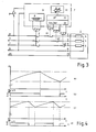
- Furnace 1 connected to the three-phase network via contactors 2 and 3.
- the connections U, V, W, the heating resistors 4, 5, 6 connected in a star circuit or a delta connection, not shown, are each connected to the phases R, S, T of the three-phase network via a switching contact of the contactor 3 and a switching contact of the contactor 2 , while the common connection of the heating resistors 4, 5, 6 is connected to the neutral conductor N of the three-phase network.
- the furnace 1 is connected to the protective conductor PE.
- a control circuit 7 is supplied with voltage by phase R via switch 8.
- Safety contactor 2 is controlled by a temperature fuse, the response temperature of which is above the upper temperature limit of the control system, but below a maximum permissible temperature
- the contactor 3 forms, together with the temperature sensor 10, a two-point controller, by means of which the stove remains connected to the three-phase network until an upper temperature limit is reached.
- the protection 3 then switches off the stove 1, whereupon the temperature of the sauna drops at a lower temperature limit the contactor 3 switches the oven 1 back on, whereupon the temperature inside the sauna rises again up to the upper temperature limit.
- FIG. 2 line a) of FIG. 2 shows the temperature as a function of time, while in line b )
- the standardized heating power P / P max is also shown as a function of time.
- the upper temperature limit in the example shown is about 4K above the lower one.
- the furnace is switched on and the temperature changes from an exponential function of the lower temperature limit to the upper.
- the start-up from the start of the adjustment is not shown, but only the steady state.
- the furnace is switched off and the temperature begins to decrease. This takes place with a longer time constant, since the heat loss through the walls of the sauna is significantly less than the heat input through the heater at full heating power.
- the furnace, the safety contactor 2 and its temperature fuse 9 essentially correspond to the parts shown in FIG. 1.
- three relays 11, 12 and 13 which can be controlled independently of one another are provided.
- a temperature sensor 14 gives the temperature values to a microprocessor 15, which is connected via a driver 16 to the coils of the relays 11, 12, 13.
- the switch-on and switch-off times are determined when the actual temperature reaches the temperature limits.
- Another control method in which one controls with switches that only know two states - namely "on" and "off” - is time-proportional control.
- the actual temperature is converted into a duty cycle within a temperature range that is comparable to the hysteresis of the two-point controller. This is generally done by comparing a voltage proportional to the temperature with a triangular voltage.
- the heating is not switched on until the actual temperature returns to the proportional band.
- the heating is accordingly switched on continuously when the actual temperature is below the proportional band
- the comparison value f (t) is usually in the form of a triangular or sawtooth-shaped voltage, while the actual value of the temperature is converted into a voltage proportional to it. Both voltages are then compared in a comparator.
- the number of switching cycles per unit of time is not directly dependent on the rate of change of the actual temperature, but is related to the frequency of the reference voltage.
- the so-called dead time of the control system is not greater than a value given by the rate of change of the actual temperature and the hysteresis.
- the relationships between the number of switching cycles per unit of time, the hysteresis and the rate of change of the actual temperature is similar to that of the two-point control.
- the number of switching cycles per unit of time is reduced by reducing the heating power of the furnace 1.
- a further development of the invention is that the relays 11, 12, 13 are driven cyclically interchanged.
- a uniform temperature distribution within the furnace and uniform relay contact wear are achieved, which considerably extends the overall service life of the relay contacts.
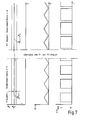
- the actual temperature for controlling the three relays 11, 12, 13 is compared with a respective comparison value that is phase-shifted by 120 ° in each case in this development.
- a sawtooth shape of the comparison value can also be provided.
- Lines e), f) and g) show the switch-on times of relays 1 1, 1 2, 1 3. Each of the relays is switched on when the difference between the actual temperature and the lower limit of the proportional band is small is less than the corresponding comparison value f (t). Electrical power is supplied to the individual heating resistors 4, 5, 6 (FIG. 3) in accordance with the time profiles shown in lines e), f) and g). The total power consumption is shown in line h) of FIG. 6 that, depending on the storage of the actual temperature from the setpoint, the three heating resistors 4, 5, 6 are switched on or off at the same time, or individual heating resistors are switched on briefly. For example, within the period during which the actual temperature is below the proportional band, the heating resistors are switched on simultaneously over a longer period of time
- control system according to the invention can be further improved by using a PI controller.
- a PI controller controlled by a microprocessor can adapt itself to the respective operating state over a very wide bandwidth. In this way, an optimal adaptation to different types of saunas with regard to the behavior of the command and disturbance variables is achieved
- Fig. 7 shows the tracking of f (t) by the I component within the proportional band for ⁇ S - ⁇ (t)> 0.
- the inversion for ⁇ S - ⁇ (t) ⁇ 0 is based on the same principle.
- the tracking via the 1 component only makes sense in the area of the proportional band.
- the P sensor is preferably used for the first sensor, and the 1- component for the second sensor.
- the invention was explained using the example of a circuit with a relay; however, semiconductor switches can also be used.
- the low switching frequency does not mean an advantage in terms of service life.
- the control system according to the invention also offers advantages when using semiconductor switches, because a conventional phase control would cause considerable mains disturbances in the case of the considerable power consumption of a sauna (12 KW). In the case of full-wave control, however, the switching frequency should also not be too high for reasons of undisturbed mains operation.
Landscapes
- Physics & Mathematics (AREA)
- General Physics & Mathematics (AREA)
- Engineering & Computer Science (AREA)
- Automation & Control Theory (AREA)
- Control Of Temperature (AREA)
- Devices For Medical Bathing And Washing (AREA)
- Medicines Containing Antibodies Or Antigens For Use As Internal Diagnostic Agents (AREA)
- Medicines Containing Plant Substances (AREA)
- Discharge Heating (AREA)
- Chair Legs, Seat Parts, And Backrests (AREA)
- Control Of Resistance Heating (AREA)
Priority Applications (1)
| Application Number | Priority Date | Filing Date | Title |
|---|---|---|---|
| AT86103812T ATE56547T1 (de) | 1985-03-29 | 1986-03-20 | Regelsystem fuer eine elektrische saunaheizung. |
Applications Claiming Priority (2)
| Application Number | Priority Date | Filing Date | Title |
|---|---|---|---|
| DE3511434 | 1985-03-29 | ||
| DE19853511434 DE3511434A1 (de) | 1985-03-29 | 1985-03-29 | Regelsystem fuer eine elektrische saunaheizung |
Publications (3)
| Publication Number | Publication Date |
|---|---|
| EP0196562A2 true EP0196562A2 (fr) | 1986-10-08 |
| EP0196562A3 EP0196562A3 (en) | 1987-09-30 |
| EP0196562B1 EP0196562B1 (fr) | 1990-09-12 |
Family
ID=6266680
Family Applications (1)
| Application Number | Title | Priority Date | Filing Date |
|---|---|---|---|
| EP86103812A Expired - Lifetime EP0196562B1 (fr) | 1985-03-29 | 1986-03-20 | Système de régulation pour un chauffage électrique de sauna |
Country Status (4)
| Country | Link |
|---|---|
| EP (1) | EP0196562B1 (fr) |
| AT (1) | ATE56547T1 (fr) |
| DE (2) | DE3511434A1 (fr) |
| FI (1) | FI83926C (fr) |
Cited By (1)
| Publication number | Priority date | Publication date | Assignee | Title |
|---|---|---|---|---|
| WO2000018349A1 (fr) * | 1998-09-25 | 2000-04-06 | Sirkjaervi Paavo | Procede de commande d'un poele electrique de sauna |
Families Citing this family (4)
| Publication number | Priority date | Publication date | Assignee | Title |
|---|---|---|---|---|
| DE102014117391A1 (de) * | 2014-11-27 | 2016-06-02 | Elka-Elektronik Gmbh | Verfahren zum Regeln einer durch eine gebäudetechnische Installation regelbaren Zustandsgröße |
| CN108181950B (zh) * | 2017-12-25 | 2020-10-20 | 河南英富迪光电科技有限公司 | 高频帧非制冷红外成像探测器的温度控制装置 |
| EP4353216A1 (fr) * | 2022-10-14 | 2024-04-17 | Tulikivi Oyj | Four électrique pour sauna |
| EP4400090A1 (fr) | 2023-01-16 | 2024-07-17 | GMW Energy-Consult UG (haftungsbeschränkt) | Procédé et système de commande de puissance de sauna interactif |
Family Cites Families (8)
| Publication number | Priority date | Publication date | Assignee | Title |
|---|---|---|---|---|
| DE1615368A1 (de) * | 1967-08-26 | 1970-05-21 | Licentia Gmbh | Unstetige elektronische Heizung |
| US3892946A (en) * | 1972-09-26 | 1975-07-01 | Helo Tehtaat Helo Fact Ltd Oy | Control system for an electrical heating device, and particularly for an electrical sauna stove |
| SE373963B (fr) * | 1973-06-14 | 1975-02-17 | Janson Sven Olof | |
| FR2270746A1 (en) * | 1974-05-06 | 1975-12-05 | Morel Jean | Electronic programmer for electrical heater - has control triacs with thermostats and time switch relays |
| DE2529184B2 (de) * | 1975-07-01 | 1977-10-27 | Licentia Patent-Verwaltungs-Gmbh, 6000 Frankfurt | Saunasteuerung |
| FR2465388A1 (fr) * | 1979-09-07 | 1981-03-20 | Messier Sa | Procede et dispositif de regulation du fonctionnement d'une installation de chauffage electrique de locaux |
| EP0040017B1 (fr) * | 1980-05-08 | 1984-07-18 | LUCAS INDUSTRIES public limited company | Système de commutation pour la connexion séquentielle des charges sur une alimentation electrique |
| FR2542885B1 (fr) * | 1983-03-16 | 1985-06-14 | Europ Equip Menager | Systeme de commande pour appareil de cuisson |
-
1985
- 1985-03-29 DE DE19853511434 patent/DE3511434A1/de not_active Withdrawn
-
1986
- 1986-03-20 DE DE8686103812T patent/DE3674032D1/de not_active Expired - Lifetime
- 1986-03-20 AT AT86103812T patent/ATE56547T1/de not_active IP Right Cessation
- 1986-03-20 EP EP86103812A patent/EP0196562B1/fr not_active Expired - Lifetime
- 1986-03-27 FI FI861343A patent/FI83926C/fi not_active IP Right Cessation
Cited By (1)
| Publication number | Priority date | Publication date | Assignee | Title |
|---|---|---|---|---|
| WO2000018349A1 (fr) * | 1998-09-25 | 2000-04-06 | Sirkjaervi Paavo | Procede de commande d'un poele electrique de sauna |
Also Published As
| Publication number | Publication date |
|---|---|
| FI83926B (fi) | 1991-06-14 |
| EP0196562A3 (en) | 1987-09-30 |
| FI861343L (fi) | 1986-09-30 |
| EP0196562B1 (fr) | 1990-09-12 |
| FI861343A0 (fi) | 1986-03-27 |
| DE3511434A1 (de) | 1986-10-02 |
| DE3674032D1 (de) | 1990-10-18 |
| FI83926C (fi) | 1993-03-23 |
| ATE56547T1 (de) | 1990-09-15 |
Similar Documents
| Publication | Publication Date | Title |
|---|---|---|
| DE2535637C3 (de) | Schaltungsanordnung für die Steuerung einer HF-lnduktionsheizung | |
| EP1091621B1 (fr) | Chauffage électrique et son procédé de contrôle | |
| EP0196562B1 (fr) | Système de régulation pour un chauffage électrique de sauna | |
| DE3540830C2 (fr) | ||
| DE102008033423A1 (de) | Backofen und Verfahren zum Betreiben eines Backofens | |
| DE2951334A1 (de) | Steuergeraet fuer elektrowaermegeraete | |
| DE3310774C2 (fr) | ||
| EP0017018B1 (fr) | Thermorégulateur | |
| EP1318696B1 (fr) | Procédé de chauffage électrique d'un four pour le traitment thermique de pièces métalliques | |
| DE2602868B1 (de) | Einrichtung zum regeln der auslauftemperatur eines elektrisch beheizten durchlauferhitzers | |
| EP0579917A2 (fr) | Dispositif de contrôle pour un appareil de cuisson verrouillable | |
| DE3815984A1 (de) | Sicherheitsschaltung fuer einen elektrischen kochherd | |
| DE3708610C2 (de) | Verfahren und Vorrichtung zur Temperaturregelung einer elektrischen Heizvorrichtung | |
| EP0321767A2 (fr) | Disposition pour le traitement électrothermique des aliments | |
| DE2154523C3 (de) | Elektrisch beheizter Durchlauferhitzer | |
| DE3709591A1 (de) | Elektrischer saunaofen | |
| EP0061152B1 (fr) | Procédé pour le fonctionnement d'une installation de climatisation à un canal pour des voitures de voyageurs | |
| DE2054412A1 (de) | Elektronischer Zweipunkt-Regler für Gefrier- und Kühlgeräte | |
| CH127393A (de) | Verfahren und Einrichtung zum Betrieb von elektrischen Glühöfen. | |
| DE10063911B4 (de) | Steuervorrichtung, Ofen und Verfahren zum Betreiben eines Ofens | |
| DE2259596A1 (de) | Stufenregler fuer zweipunktregelung mit schaltstufen | |
| EP0075708A2 (fr) | Cathode à chauffage direct avec réglage du chauffage dans des appareils à faisceau électronique et méthode pour son fonctionnement | |
| DE29923543U1 (de) | Elektrische Heizung | |
| EP1431681B1 (fr) | Chauffe-eau instantané | |
| AT398127B (de) | Wasserheizungsanlage |
Legal Events
| Date | Code | Title | Description |
|---|---|---|---|
| PUAI | Public reference made under article 153(3) epc to a published international application that has entered the european phase |
Free format text: ORIGINAL CODE: 0009012 |
|
| 17P | Request for examination filed |
Effective date: 19860320 |
|
| AK | Designated contracting states |
Kind code of ref document: A2 Designated state(s): AT BE CH DE FR GB IT LI LU NL SE |
|
| PUAL | Search report despatched |
Free format text: ORIGINAL CODE: 0009013 |
|
| AK | Designated contracting states |
Kind code of ref document: A3 Designated state(s): AT BE CH DE FR GB IT LI LU NL SE |
|
| 17Q | First examination report despatched |
Effective date: 19890113 |
|
| GRAA | (expected) grant |
Free format text: ORIGINAL CODE: 0009210 |
|
| AK | Designated contracting states |
Kind code of ref document: B1 Designated state(s): AT BE CH DE FR GB IT LI LU NL SE |
|
| ITF | It: translation for a ep patent filed | ||
| REF | Corresponds to: |
Ref document number: 56547 Country of ref document: AT Date of ref document: 19900915 Kind code of ref document: T |
|
| GBT | Gb: translation of ep patent filed (gb section 77(6)(a)/1977) | ||
| REF | Corresponds to: |
Ref document number: 3674032 Country of ref document: DE Date of ref document: 19901018 |
|
| ET | Fr: translation filed | ||
| PLBE | No opposition filed within time limit |
Free format text: ORIGINAL CODE: 0009261 |
|
| STAA | Information on the status of an ep patent application or granted ep patent |
Free format text: STATUS: NO OPPOSITION FILED WITHIN TIME LIMIT |
|
| 26N | No opposition filed | ||
| PGFP | Annual fee paid to national office [announced via postgrant information from national office to epo] |
Ref country code: LU Payment date: 19920220 Year of fee payment: 7 |
|
| EPTA | Lu: last paid annual fee | ||
| PGFP | Annual fee paid to national office [announced via postgrant information from national office to epo] |
Ref country code: GB Payment date: 19930215 Year of fee payment: 8 |
|
| PGFP | Annual fee paid to national office [announced via postgrant information from national office to epo] |
Ref country code: BE Payment date: 19930216 Year of fee payment: 8 |
|
| PGFP | Annual fee paid to national office [announced via postgrant information from national office to epo] |
Ref country code: FR Payment date: 19930219 Year of fee payment: 8 |
|
| PG25 | Lapsed in a contracting state [announced via postgrant information from national office to epo] |
Ref country code: LU Free format text: LAPSE BECAUSE OF NON-PAYMENT OF DUE FEES Effective date: 19930320 |
|
| ITTA | It: last paid annual fee | ||
| PGFP | Annual fee paid to national office [announced via postgrant information from national office to epo] |
Ref country code: NL Payment date: 19930331 Year of fee payment: 8 |
|
| PG25 | Lapsed in a contracting state [announced via postgrant information from national office to epo] |
Ref country code: GB Effective date: 19940320 |
|
| PG25 | Lapsed in a contracting state [announced via postgrant information from national office to epo] |
Ref country code: BE Effective date: 19940331 |
|
| BERE | Be: lapsed |
Owner name: WELLA A.G. Effective date: 19940331 |
|
| PG25 | Lapsed in a contracting state [announced via postgrant information from national office to epo] |
Ref country code: NL Effective date: 19941001 |
|
| GBPC | Gb: european patent ceased through non-payment of renewal fee |
Effective date: 19940320 |
|
| NLV4 | Nl: lapsed or anulled due to non-payment of the annual fee | ||
| PG25 | Lapsed in a contracting state [announced via postgrant information from national office to epo] |
Ref country code: FR Effective date: 19941130 |
|
| REG | Reference to a national code |
Ref country code: FR Ref legal event code: ST |
|
| EAL | Se: european patent in force in sweden |
Ref document number: 86103812.3 |
|
| PGFP | Annual fee paid to national office [announced via postgrant information from national office to epo] |
Ref country code: AT Payment date: 19980223 Year of fee payment: 13 |
|
| PGFP | Annual fee paid to national office [announced via postgrant information from national office to epo] |
Ref country code: CH Payment date: 19980224 Year of fee payment: 13 |
|
| PG25 | Lapsed in a contracting state [announced via postgrant information from national office to epo] |
Ref country code: AT Free format text: LAPSE BECAUSE OF NON-PAYMENT OF DUE FEES Effective date: 19990320 |
|
| PG25 | Lapsed in a contracting state [announced via postgrant information from national office to epo] |
Ref country code: LI Free format text: LAPSE BECAUSE OF NON-PAYMENT OF DUE FEES Effective date: 19990331 Ref country code: CH Free format text: LAPSE BECAUSE OF NON-PAYMENT OF DUE FEES Effective date: 19990331 |
|
| REG | Reference to a national code |
Ref country code: CH Ref legal event code: PL |
|
| PGFP | Annual fee paid to national office [announced via postgrant information from national office to epo] |
Ref country code: DE Payment date: 20050309 Year of fee payment: 20 |
|
| PGFP | Annual fee paid to national office [announced via postgrant information from national office to epo] |
Ref country code: SE Payment date: 20050310 Year of fee payment: 20 |
|
| PG25 | Lapsed in a contracting state [announced via postgrant information from national office to epo] |
Ref country code: IT Free format text: LAPSE BECAUSE OF NON-PAYMENT OF DUE FEES;WARNING: LAPSES OF ITALIAN PATENTS WITH EFFECTIVE DATE BEFORE 2007 MAY HAVE OCCURRED AT ANY TIME BEFORE 2007. THE CORRECT EFFECTIVE DATE MAY BE DIFFERENT FROM THE ONE RECORDED. Effective date: 20050320 |
|
| EUG | Se: european patent has lapsed |