EP0196575A2 - Dispositif pour mélanger au moins un milieu fluide - Google Patents
Dispositif pour mélanger au moins un milieu fluide Download PDFInfo
- Publication number
- EP0196575A2 EP0196575A2 EP86103912A EP86103912A EP0196575A2 EP 0196575 A2 EP0196575 A2 EP 0196575A2 EP 86103912 A EP86103912 A EP 86103912A EP 86103912 A EP86103912 A EP 86103912A EP 0196575 A2 EP0196575 A2 EP 0196575A2
- Authority
- EP
- European Patent Office
- Prior art keywords
- pump impellers
- pump
- impellers
- flow
- inner shaft
- Prior art date
- Legal status (The legal status is an assumption and is not a legal conclusion. Google has not performed a legal analysis and makes no representation as to the accuracy of the status listed.)
- Granted
Links
Images


Classifications
-
- B—PERFORMING OPERATIONS; TRANSPORTING
- B01—PHYSICAL OR CHEMICAL PROCESSES OR APPARATUS IN GENERAL
- B01F—MIXING, e.g. DISSOLVING, EMULSIFYING OR DISPERSING
- B01F27/00—Mixers with rotary stirring devices in fixed receptacles; Kneaders
- B01F27/40—Mixers with rotor-rotor system, e.g. with intermeshing teeth
- B01F27/41—Mixers with rotor-rotor system, e.g. with intermeshing teeth with the mutually rotating surfaces facing each other
- B01F27/412—Mixers with rotor-rotor system, e.g. with intermeshing teeth with the mutually rotating surfaces facing each other provided with ribs, ridges or grooves on one surface
-
- B—PERFORMING OPERATIONS; TRANSPORTING
- B01—PHYSICAL OR CHEMICAL PROCESSES OR APPARATUS IN GENERAL
- B01F—MIXING, e.g. DISSOLVING, EMULSIFYING OR DISPERSING
- B01F27/00—Mixers with rotary stirring devices in fixed receptacles; Kneaders
- B01F27/80—Mixers with rotary stirring devices in fixed receptacles; Kneaders with stirrers rotating about a substantially vertical axis
- B01F27/81—Mixers with rotary stirring devices in fixed receptacles; Kneaders with stirrers rotating about a substantially vertical axis the stirrers having central axial inflow and substantially radial outflow
-
- B—PERFORMING OPERATIONS; TRANSPORTING
- B01—PHYSICAL OR CHEMICAL PROCESSES OR APPARATUS IN GENERAL
- B01F—MIXING, e.g. DISSOLVING, EMULSIFYING OR DISPERSING
- B01F27/00—Mixers with rotary stirring devices in fixed receptacles; Kneaders
- B01F27/80—Mixers with rotary stirring devices in fixed receptacles; Kneaders with stirrers rotating about a substantially vertical axis
- B01F27/84—Mixers with rotary stirring devices in fixed receptacles; Kneaders with stirrers rotating about a substantially vertical axis with two or more stirrers rotating at different speeds or in opposite directions about the same axis
Definitions
- the invention relates to a device for mixing at least one flow medium, wherein at least two partial flows of the flow medium are brought together to produce a turbulent flow.
- Turbulence in flow media that is as strong as possible can be exploited in numerous chemical and physical processes. It is known that the greater a - fluctuating movement to the main flow direction, the more turbulent is a flow. It is known to direct a control flow transversely to a main flow in order to achieve a change from laminar flow to turbulent flow at the impact heads. At this envelope, the pressure drops sharply and the flow media "jump" in the transverse direction, so to speak. (See Lueger, Lexikon dertechnik fourth edition, volume 1 and 14, pages 587 and 589, and pages 521, 522).
- the aim is to create a device with which great turbulence can be achieved in an economical manner.
- the device according to the invention is characterized by at least two pump impellers which are parallel to one another and coaxially arranged with respect to one another for the partial flows, adjacent pump impellers being in opposite directions.
- Fig. 1 there are two pump impellers 1 and 2 which are parallel and coaxial to each other. Both pump impellers 1 and 2 rotate about one and the same axis 3, but in the opposite direction of rotation. A first part flow flows in the direction of the arrows 4 to the pump impeller 1, and a second part flow flows in the direction of the arrows 5 to the second pump impeller 2.
- the first partial flow 6 emerges from the pump impeller 1 as a rotating medium disk
- the second partial stream 7 likewise emerges from the pump impeller 2 as a rotating medium disk. Both media discs 6 and 7 rotate in opposite directions.
- the two pump impellers 1 and 2 are expediently designed identically to one another and consequently, apart from the direction of rotation, have the same hydrodynamic characteristics.
- the two oppositely rotating liquid disks 6 and 7 touch each other in the envelope 8, the two opposite circumferential components of the two liquid whey disks meeting each other and canceling each other practically immediately.
- the two liquid disks 6 and 7 have low radial speed components that determine the throughput of the pump impellers. Because of the sudden abolition of the mutually opposed tangential speed components, oscillating transverse movements of the liquid particles occur, which result in a very large amount of turbulence in the liquid region 9.
- the two pump impellers 1 and 2 are shown somewhat more clearly.
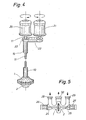
- the pump impeller 1 is carried by a hollow shaft 10, and the pump impeller 2 is seated on an inner shaft 11 which is surrounded by the hollow shaft 10.
- the pump impeller 1 has a suction nozzle 12 for the partial flow 4
- the pump impeller 2 has a suction nozzle 13 for the partial flow 5. Both pump impellers 1 and 2 rotate in opposite directions about the axis 3.
- the two pump impellers 1 and 2 are driven by a single drive motor 14 for rotating in opposite directions.
- the pump impeller 1 sits on the hollow shaft 10 and the pump impeller 2 is carried by the inner shaft 11.
- the drive motor 14 drives via a belt 15 on pinions 16 and 17.
- the pinion 17 is rotatably connected to the inner shaft 11.
- the pinion 16 is rotatably connected to a wheel 18 which meshes with a wheel 19 which is rotatably connected to the hollow shaft 10. In this way, the two shafts 10 and 11 are driven in opposite directions.
- the two pump impellers 1 and 2 are driven in opposite directions by two drive motors 20 and 21.
- the motor 20 drives directly on the inner shaft 11 on which the pump impeller 2 is seated, and the motor 21 drives via a belt 22 on a pulley 23 which is connected to the hollow shaft 10 in a rotationally fixed manner.
- the two motors 20 and 21 have opposite directions of rotation.
- the pump impeller 1 is seated on a shaft 24, and the pump impeller 2 is seated on a shaft 25.
- the two coaxial drive shafts 24 and 25 of the two pump impellers 1 and 2 are thus on opposite sides of the pump impellers.
- a motor 26 is used to drive the shaft 24 and thus the pump impeller 1
- a motor 27 is used to drive the shaft 25 and thus the pump impeller 2.
- An intake port 28 leads to the pump impeller 1 and an intake port 29 leads to the pump impeller 2 merged flow media flow away via a nozzle 30.
- the pump impellers 1 and 2 are designed as centrifugal wheels. If the pump impellers 1 and 2 have forward curved blades, the peripheral component of the speed of the emerging liquid disks 6 and 7 can be increased very much. The circumferential component of the speed (tangential speed) of the two liquid disks 6 and 7 can be set correspondingly large by appropriate speed of the pump impellers 1 and 2.
Landscapes
- Chemical & Material Sciences (AREA)
- Chemical Kinetics & Catalysis (AREA)
- Structures Of Non-Positive Displacement Pumps (AREA)
- Mixers Of The Rotary Stirring Type (AREA)
- Paper (AREA)
Priority Applications (1)
| Application Number | Priority Date | Filing Date | Title |
|---|---|---|---|
| AT86103912T ATE70203T1 (de) | 1985-04-03 | 1986-03-21 | Vorrichtung zum durchmischen von zumindest einem stroemungsmedium. |
Applications Claiming Priority (2)
| Application Number | Priority Date | Filing Date | Title |
|---|---|---|---|
| CH1453/85 | 1985-04-03 | ||
| CH1453/85A CH665959A5 (de) | 1985-04-03 | 1985-04-03 | Vorrichtung zum durchmischen von zumindest einem stroemungsmedium. |
Publications (3)
| Publication Number | Publication Date |
|---|---|
| EP0196575A2 true EP0196575A2 (fr) | 1986-10-08 |
| EP0196575A3 EP0196575A3 (en) | 1988-11-30 |
| EP0196575B1 EP0196575B1 (fr) | 1991-12-11 |
Family
ID=4210820
Family Applications (1)
| Application Number | Title | Priority Date | Filing Date |
|---|---|---|---|
| EP86103912A Expired - Lifetime EP0196575B1 (fr) | 1985-04-03 | 1986-03-21 | Dispositif pour mélanger au moins un milieu fluide |
Country Status (6)
| Country | Link |
|---|---|
| US (1) | US4786183A (fr) |
| EP (1) | EP0196575B1 (fr) |
| JP (1) | JPH0790160B2 (fr) |
| AT (1) | ATE70203T1 (fr) |
| CH (1) | CH665959A5 (fr) |
| DE (1) | DE3682799D1 (fr) |
Cited By (1)
| Publication number | Priority date | Publication date | Assignee | Title |
|---|---|---|---|---|
| WO2015032008A1 (fr) | 2013-09-06 | 2015-03-12 | Miteco Ag | Dispositif pour mélanger et/ou homogénéiser au moins un produit liquide |
Families Citing this family (4)
| Publication number | Priority date | Publication date | Assignee | Title |
|---|---|---|---|---|
| DE20002920U1 (de) | 2000-02-18 | 2000-04-20 | Schröder & Boos Misch- und Anlagentechnik GmbH & Co. KG, 27578 Bremerhaven | Homogenisator |
| US6607783B1 (en) | 2000-08-24 | 2003-08-19 | Kimberly-Clark Worldwide, Inc. | Method of applying a foam composition onto a tissue and tissue products formed therefrom |
| JP2015066503A (ja) * | 2013-09-30 | 2015-04-13 | 大日本印刷株式会社 | 撹拌装置および撹拌方法 |
| KR101780329B1 (ko) * | 2015-05-06 | 2017-09-20 | 주식회사 케이엔에스컴퍼니 | 로터-로터 방식 분산유화장치 임펠러 구조 시스템 |
Family Cites Families (12)
| Publication number | Priority date | Publication date | Assignee | Title |
|---|---|---|---|---|
| FR744390A (fr) * | 1933-04-19 | |||
| GB1051539A (fr) * | 1900-01-01 | |||
| GB205672A (en) * | 1922-10-11 | 1923-10-25 | Edgar Allison Burrows | Improvements in the means for and method of mixing the ingredients used in the manufacture of soap, in a mixing pan |
| DE648783C (de) * | 1934-09-02 | 1937-08-09 | Johann Aebi | Farbmischmaschine |
| FR950579A (fr) * | 1947-07-23 | 1949-09-30 | Separation Sa Franc Pour La | Perfectionnements aux procédés, dispositifs et installations mettant en jeu des opérations de pulvérisation et d'atomisation |
| CH341478A (de) * | 1955-08-12 | 1959-10-15 | Peter Prof Willems | Knet- und Mischwerk |
| US3147957A (en) * | 1960-05-31 | 1964-09-08 | W J Cooper | Liquid mixing device |
| DE1454743B2 (de) * | 1962-06-07 | 1970-05-14 | Beck, Erich, 6520 Worms | Verfahren und Vorrichtung zum Verdichten und Agglomerieren von pulverförmigen bis körnigen thermoplastischen Stoffen |
| FR1404962A (fr) * | 1963-08-22 | 1965-07-02 | Appareil de dosage et de mélange pour fluides | |
| US3252690A (en) * | 1964-06-15 | 1966-05-24 | Warner J Cooper | Liquid mixing device |
| JPS4836764A (fr) * | 1971-09-16 | 1973-05-30 | ||
| US3942766A (en) * | 1974-03-08 | 1976-03-09 | Lage James R | Process and arrangement for producing a strong turbulence in at least one fluid or quasi-fluid medium |
-
1985
- 1985-04-03 CH CH1453/85A patent/CH665959A5/de not_active IP Right Cessation
-
1986
- 1986-03-21 AT AT86103912T patent/ATE70203T1/de not_active IP Right Cessation
- 1986-03-21 DE DE8686103912T patent/DE3682799D1/de not_active Expired - Lifetime
- 1986-03-21 EP EP86103912A patent/EP0196575B1/fr not_active Expired - Lifetime
- 1986-03-25 US US06/843,780 patent/US4786183A/en not_active Expired - Lifetime
- 1986-04-02 JP JP61074390A patent/JPH0790160B2/ja not_active Expired - Lifetime
Cited By (1)
| Publication number | Priority date | Publication date | Assignee | Title |
|---|---|---|---|---|
| WO2015032008A1 (fr) | 2013-09-06 | 2015-03-12 | Miteco Ag | Dispositif pour mélanger et/ou homogénéiser au moins un produit liquide |
Also Published As
| Publication number | Publication date |
|---|---|
| CH665959A5 (de) | 1988-06-30 |
| EP0196575B1 (fr) | 1991-12-11 |
| JPS61230726A (ja) | 1986-10-15 |
| US4786183A (en) | 1988-11-22 |
| JPH0790160B2 (ja) | 1995-10-04 |
| ATE70203T1 (de) | 1991-12-15 |
| EP0196575A3 (en) | 1988-11-30 |
| DE3682799D1 (de) | 1992-01-23 |
Similar Documents
| Publication | Publication Date | Title |
|---|---|---|
| DE69914134T2 (de) | Laufrad | |
| DE3885167T2 (de) | Verbund-Vakuum- und Verflüssigungspumpe. | |
| DE69008541T2 (de) | Druckaustauscher. | |
| DE4006604C2 (fr) | ||
| DE7005689U (de) | Ventilator. | |
| WO2000023714A1 (fr) | Pompe a anneau fluide | |
| DE3715331A1 (de) | Homogenisator fuer die herstellung fliessfaehiger produkte | |
| DE1757113B1 (de) | Vorrichtung zum umruehren von fluessigkeit | |
| EP0196575A2 (fr) | Dispositif pour mélanger au moins un milieu fluide | |
| DE564826C (de) | Einrichtung zur Foerderung von Gasen oder Fluessigkeiten mit einem Schraubenrad im Einlaufkanal eines Fliehkraftrades und zwischen Schrauben- und Fliehkraftrad eingeschaltetem, von innen nach aussen durchstroemtem Diffusor | |
| DE69616562T2 (de) | Halbaxialgebläse | |
| DE821734C (de) | Einrichtung zur Drehzahlbegrenzung von Gasturbinen | |
| DE69212074T2 (de) | Flüssigkeitspumpe | |
| EP0008395A1 (fr) | Dispositif pour séparer des liquides de suspensions | |
| DE1964308B2 (de) | Vorrichtung zum Begasen und Umwälzen von Flüssigkeiten | |
| DE4124906C2 (de) | Kernloser Drehmomentwandler | |
| DE1447328B2 (de) | Fluessigkeitspfeife | |
| EP0947472A1 (fr) | Aérateur giroscopic | |
| DE3319921C2 (fr) | ||
| DE3802949C2 (fr) | ||
| DE4137496A1 (de) | Filter zur dynamischen filtration | |
| DE163111C (fr) | ||
| DE1500454C3 (de) | Hydraulischer Drehmomentwandler oder hydraulische Kupplung | |
| DE3704538A1 (de) | Ruehrmischer | |
| DE3048436A1 (de) | Rotierender diffusor fuer schlammpumpen |
Legal Events
| Date | Code | Title | Description |
|---|---|---|---|
| PUAI | Public reference made under article 153(3) epc to a published international application that has entered the european phase |
Free format text: ORIGINAL CODE: 0009012 |
|
| AK | Designated contracting states |
Kind code of ref document: A2 Designated state(s): AT BE DE FR GB IT LU NL SE |
|
| PUAL | Search report despatched |
Free format text: ORIGINAL CODE: 0009013 |
|
| AK | Designated contracting states |
Kind code of ref document: A3 Designated state(s): AT BE DE FR GB IT LU NL SE |
|
| 17P | Request for examination filed |
Effective date: 19890524 |
|
| 17Q | First examination report despatched |
Effective date: 19900111 |
|
| GRAA | (expected) grant |
Free format text: ORIGINAL CODE: 0009210 |
|
| AK | Designated contracting states |
Kind code of ref document: B1 Designated state(s): AT BE DE FR GB IT LU NL SE |
|
| REF | Corresponds to: |
Ref document number: 70203 Country of ref document: AT Date of ref document: 19911215 Kind code of ref document: T |
|
| GBT | Gb: translation of ep patent filed (gb section 77(6)(a)/1977) | ||
| ITF | It: translation for a ep patent filed | ||
| REF | Corresponds to: |
Ref document number: 3682799 Country of ref document: DE Date of ref document: 19920123 |
|
| ET | Fr: translation filed | ||
| PLBE | No opposition filed within time limit |
Free format text: ORIGINAL CODE: 0009261 |
|
| STAA | Information on the status of an ep patent application or granted ep patent |
Free format text: STATUS: NO OPPOSITION FILED WITHIN TIME LIMIT |
|
| 26N | No opposition filed | ||
| EPTA | Lu: last paid annual fee | ||
| EAL | Se: european patent in force in sweden |
Ref document number: 86103912.1 |
|
| REG | Reference to a national code |
Ref country code: GB Ref legal event code: IF02 |
|
| PGFP | Annual fee paid to national office [announced via postgrant information from national office to epo] |
Ref country code: GB Payment date: 20050314 Year of fee payment: 20 |
|
| PGFP | Annual fee paid to national office [announced via postgrant information from national office to epo] |
Ref country code: SE Payment date: 20050324 Year of fee payment: 20 Ref country code: IT Payment date: 20050324 Year of fee payment: 20 Ref country code: DE Payment date: 20050324 Year of fee payment: 20 |
|
| PGFP | Annual fee paid to national office [announced via postgrant information from national office to epo] |
Ref country code: LU Payment date: 20050325 Year of fee payment: 20 Ref country code: FR Payment date: 20050325 Year of fee payment: 20 |
|
| PGFP | Annual fee paid to national office [announced via postgrant information from national office to epo] |
Ref country code: AT Payment date: 20050329 Year of fee payment: 20 |
|
| PGFP | Annual fee paid to national office [announced via postgrant information from national office to epo] |
Ref country code: NL Payment date: 20050331 Year of fee payment: 20 |
|
| PGFP | Annual fee paid to national office [announced via postgrant information from national office to epo] |
Ref country code: BE Payment date: 20050502 Year of fee payment: 20 |
|
| PG25 | Lapsed in a contracting state [announced via postgrant information from national office to epo] |
Ref country code: GB Free format text: LAPSE BECAUSE OF EXPIRATION OF PROTECTION Effective date: 20060320 |
|
| PG25 | Lapsed in a contracting state [announced via postgrant information from national office to epo] |
Ref country code: NL Free format text: LAPSE BECAUSE OF EXPIRATION OF PROTECTION Effective date: 20060321 |
|
| REG | Reference to a national code |
Ref country code: GB Ref legal event code: PE20 |
|
| EUG | Se: european patent has lapsed | ||
| NLV7 | Nl: ceased due to reaching the maximum lifetime of a patent |
Effective date: 20060321 |
|
| BE20 | Be: patent expired |
Owner name: *CADEOANGELO Effective date: 20060321 Owner name: *MITECO A.G. Effective date: 20060321 |