EP0196605A2 - Magnetkopfanordnung - Google Patents
Magnetkopfanordnung Download PDFInfo
- Publication number
- EP0196605A2 EP0196605A2 EP86104099A EP86104099A EP0196605A2 EP 0196605 A2 EP0196605 A2 EP 0196605A2 EP 86104099 A EP86104099 A EP 86104099A EP 86104099 A EP86104099 A EP 86104099A EP 0196605 A2 EP0196605 A2 EP 0196605A2
- Authority
- EP
- European Patent Office
- Prior art keywords
- core
- magnetic head
- head assembly
- magnetic
- assembly according
- Prior art date
- Legal status (The legal status is an assumption and is not a legal conclusion. Google has not performed a legal analysis and makes no representation as to the accuracy of the status listed.)
- Withdrawn
Links
Images




Classifications
-
- G—PHYSICS
- G11—INFORMATION STORAGE
- G11B—INFORMATION STORAGE BASED ON RELATIVE MOVEMENT BETWEEN RECORD CARRIER AND TRANSDUCER
- G11B5/00—Recording by magnetisation or demagnetisation of a record carrier; Reproducing by magnetic means; Record carriers therefor
- G11B5/10—Structure or manufacture of housings or shields for heads
-
- G—PHYSICS
- G11—INFORMATION STORAGE
- G11B—INFORMATION STORAGE BASED ON RELATIVE MOVEMENT BETWEEN RECORD CARRIER AND TRANSDUCER
- G11B5/00—Recording by magnetisation or demagnetisation of a record carrier; Reproducing by magnetic means; Record carriers therefor
- G11B5/012—Recording on, or reproducing or erasing from, magnetic disks
-
- G—PHYSICS
- G11—INFORMATION STORAGE
- G11B—INFORMATION STORAGE BASED ON RELATIVE MOVEMENT BETWEEN RECORD CARRIER AND TRANSDUCER
- G11B5/00—Recording by magnetisation or demagnetisation of a record carrier; Reproducing by magnetic means; Record carriers therefor
- G11B5/127—Structure or manufacture of heads, e.g. inductive
-
- G—PHYSICS
- G11—INFORMATION STORAGE
- G11B—INFORMATION STORAGE BASED ON RELATIVE MOVEMENT BETWEEN RECORD CARRIER AND TRANSDUCER
- G11B5/00—Recording by magnetisation or demagnetisation of a record carrier; Reproducing by magnetic means; Record carriers therefor
- G11B5/127—Structure or manufacture of heads, e.g. inductive
- G11B5/265—Structure or manufacture of a head with more than one gap for erasing, recording or reproducing on the same track
- G11B5/2652—Structure or manufacture of a head with more than one gap for erasing, recording or reproducing on the same track with more than one gap simultaneously operative
- G11B5/2654—Structure or manufacture of a head with more than one gap for erasing, recording or reproducing on the same track with more than one gap simultaneously operative for recording or erasing
-
- G—PHYSICS
- G11—INFORMATION STORAGE
- G11B—INFORMATION STORAGE BASED ON RELATIVE MOVEMENT BETWEEN RECORD CARRIER AND TRANSDUCER
- G11B5/00—Recording by magnetisation or demagnetisation of a record carrier; Reproducing by magnetic means; Record carriers therefor
- G11B5/48—Disposition or mounting of heads or head supports relative to record carriers ; arrangements of heads, e.g. for scanning the record carrier to increase the relative speed
- G11B5/488—Disposition of heads
- G11B5/4886—Disposition of heads relative to rotating disc
Definitions
- the present invention relates to a magnetic head assembly for floppy disks, hard disks or video disks, and more specifically to a magnetic head assembly with a plurality of cores of different types, characteristics, etc.
- Magnetic head assembly 2 has ceramic slider 4. Slider groove 6 is cut in the center of that surface of slider 4 which contacts a floppy disk, extending along the transfer direction of the disk.
- One core assembly 7 is integrally coupled to slider 4.
- the core assembly includes read/write core 8 and two erase cores 10 on either side thereof. The cores are shaped like sheets and are stacked and bonded to one another. Core 8 is formed with read/write gap 12, and each core 10 with erase gap 14.
- Core assembly 7 of magnetic head assembly 2 must be of a type and properties best suited for the recording system and recording density used. If the longitudinal recording system is used, for example, the core assembly must be of a tunnel erase type, as shown in F ig. 1. If the perpendicular recording system is used, the core assembly must be of a leading wide erase type. If the recording density of the magnetic recording system is higher, then the read/write gap of the core assembly used is narrowed in proportion.
- the object of the present invention is to provide a magnetic head assembly capable of writing in and/or reading information from a magnetic disk in a plurality of modes using different magnetic recording systems and different recording densities.
- the magnetic disk apparatuses with the magnetic head assemblies of the invention are compatible with one another.
- the above object of the present invention is achieved by providing a magnetic head assembly with a plurality of coil-including core assemblies which are different in type, properties, etc.
- the core assemblies are alternatively used in accordance with the magnetic recording system and recording density required.
- first and second core assemblies of different types and properties are arranged on either side of a slider groove which is formed in the center of the magnetic head assembly.
- the distance between the first and second core assemblies is an integral multiple of the track pitch of the magnetic disk. Therefore, the two core assemblies can be located over different tracks of the disk.
- the first and second core assemblies can be replaced with each other, for alternative use, by only changing the track number of a program in a control device of a drive mechanism for the magnetic head assembly, without requiring any mechanical switching means.
- first and second core assemblies are arranged on one side of a slider groove.
- Magnetic head assemblies with this arrangement are adapted for use with a double-sided recording system. If two such head assemblies are opposed to each other, each in contact with its corresponding side of the magnetic.disk, their core assemblies cannot face one another. Thus, magnetic coupling can never take place between the core assemblies.
- carriage 20 is guided by a pair of guide rails 21 for movement in the radial direction of a floppy disk (not shown).
- Magnetic head assembly 32 is mounted on the front end portion of carriage 20 by means of gimbals plate 22.
- Pulley 28, which is mounted on the shaft (not shown) of stepping motor 30, is disposed beside carriage 20.
- the middle portion of thin, flexible steel belt 26 is wound around pulley 28. Both ends of belt 26 are fixed to belt holder 24 which is attached to carriage 20.
- carriage 20 moves in the radial direction of.the floppy disk for a distance corresponding to the angle of rotation of pulley 28.
- the moved distance of carriage 20 is an integral multiple of the track pitch of the disk.
- magnetic head assembly 32 on carriage 20 is always located over any track of the disk.
- the drive of motor 30 is controlled by a conventional control device (not shown).
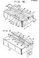
- Figs. 3A and 3B shows magnetic head assembly 32 according to a first embodiment of the present invention.
- numeral 34 designates a ceramic slider.
- Slider groove 36 is formed in the center of that surface of slider 34 in contact with the floppy disk, extending along the transfer direction of the disk. While the disk is rotating in contact with assembly 32, air is introduced into the space between the contact surfaces of the disk and assembly 32 through groove 36 and both side edge portions of the assembly. Thus, the gas lubrication characteristic between head and disk is improved.
- Magnetic head assembly 32 comprises first and second core assemblies 37 and 39.
- Assembly 37 is disposed on one side of slider groove 36, and assembly 39 on the other. Both these assemblies are bulk-type core assemblies.
- First core assembly 37 which is of a leading wide erase type, includes read/write core 38 and erase core 43. As shown in Figs. 3A and 3B cores 38 and 43 are formed with read/write gap 42 and leading wide erase gap 46, respectively.
- Coils 38a and 43a are provided in cores 38 and 43, respectively.
- Assembly 37 is adapted for use with the perpendicular magnetic recording system, and is used in reading information which is recorded on the disk by that recording system.
- second core assembly 39 which is of a tunnel erase type, includes read/write core 41 and erase core 40. Cores 41 and 40 are formed with read/write gap 44 and erase gap 48, respectively. Assembly 39 is adapted for use with the longitudinal magnetic recording system, and is used in writing data on the floppy disk in accordance with such system or in reading information which is recorded on the disk by that recording system.
- a coil is mounted in cores 41 and 40 of second core assembly 39 as in the case.of first core assembly.
- Read/write gap 42 of core 38 in first core assembly 37 and read/write gap 44 of core 41 in second core assembly 39 are arranged in a straight line in a direction transverse to that of a movement of the floppy disk.
- first and second core assemblies 37 and 39 are adjusted to an integral multiple of the track pitch of the floppy disk. Therefore, the two assemblies are bound to be located on different tracks. If distance P 1 between the assemblies is longer than the track pitch by factor m, and if assembly 37 is located over the nth track, then assembly 39 is located over the (n + m)th track. Thus, in replacing assemblies 37 and 39 with each other for alternative use, what is necessary is only to change the track number of the program of a control device for the drive of the carriage. If the control device is programmed in confom- ity to first core assembly 37, for example, the track number should only be changed from n to (n + m) when second core assembly 39 is to be used. Thus, the alternative use of the two assemblies does not require any mechanical switching means.
- Fig. 4 shows a magnetic head assembly according to a second embodiment of the present invention.
- Head assembly 32 of this embodiment is well adapted for a system in which information is recorded on both sides of a floppy disk.
- first and second core assemblies 37 and 39 are arranged on one side of slider groove 36.
- Auxiliary slider groove 50 is formed between assemblies 37 and 39.
- two magnetic head assemblies are arranged so as to face each other across the floppy disk. If two such head assemblies as are shown in Fig. 3 are used, therefore, their core assemblies face one another to cause magnetic coupling between them.
- noises attributed to the magnetic coupling would inevitably be recorded on that side of the disk opposite to the side on which the information is to be written.
- Even though the magnetic head assemblies of the type shown in Fig. 4 are opposed to each other, however, their core assemblies cannot face one another, avoiding the aforesaid awkward situation.
- distance P2 between first and second core assemblies 37 and 39 and distances P 3 and P 4 between assembly 37 and the center line of slider groove 36, or of the magnetic head assembly, and between assembly 39 and the center line are all integral multiples of the track pitch.
- core assemblies 37 and 39 are bound to be located over different tracks of the floppy disk, and do not require any mechanical switching means for alternatively selecting the core assemblies.
- Figs. 5A and 5B shows magnetic head assembly according to a third embodiment of the present invention.
- first and second core assemblies 52 and 54 of a laminate type are arranged on either side of slider groove 36. Both these core assemblies are of a tunnel erase type.
- the first core assembly is intended for high-density magnetic recording, and the second one for low-density recording.
- Assembly 52 includes read/write core 56 and erase cores 60 on either side of core 56.
- core 56 is formed with read/write gap 64, and each core 60 with erase gap 68.
- assembly 54 includes read/write core 58 and erase cores 62 on either side of core 58.
- Core 58 is formed with read/write gap 66, and each core 62 with erase gap 70. Gap 64 of assembly 52 is narrower than gap 66 of assembly 54. As shown in Fig. 3B coils 56a, 58a, 60a and 62a are provided in cores 56, 58, 60 and 62.
- Fig. 6 is a perspective view of a magnetic head assembly according ' to a fourth embodiment of the present invention.
- first and second core assemblies 52 and 54 similar to those shown in Fig. 5 are arranged only on one side of slider groove 36.
- Auxiliary slider groove 72 is formed between assemblies 52 and 54.
- the magnetic head assembly of this embodiment is adapted for use with the double-sided recording system.
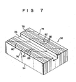
- Fig. 7 is a perspective view of a magnetic head assembly according to a fifth embodiment of the present invention.
- first and second core assemblies 74 and 76 of a laminate type are arranged on either side of slider groove 36. Both these core assemblies are of a straddle type.
- Assemblies 74 and 76 include read/write cores 78 and 80, respectively, which are formed with read/write gaps 82 and 84, respectively.
- Erase cores 86 are disposed on either side of core 78, and erase cores 88 on either side of core 80. The gaps between the erase cores and read/write cores are defined as erase gaps.
- First and second core assemblies 74 and 76 are intended for high- and low-density magnetic recording, respectively. Gap 82 is narrower than gap 84.
- the present invention is not limited to the embodiments described above.
- the magnetic head assembly of the invention may comprise three or more core assemblies without any change in the fundamental configuration.
- the present invention is not limited to the magnetic head assemblies for floppy disks, and may also be applied to those for video disks and other magnetic disks. In these cases, the head assemblies do not require any erase cores.
Landscapes
- Engineering & Computer Science (AREA)
- Manufacturing & Machinery (AREA)
- Adjustment Of The Magnetic Head Position Track Following On Tapes (AREA)
- Magnetic Heads (AREA)
Applications Claiming Priority (2)
| Application Number | Priority Date | Filing Date | Title |
|---|---|---|---|
| JP67546/85 | 1985-03-30 | ||
| JP60067546A JPS61227209A (ja) | 1985-03-30 | 1985-03-30 | 磁気ヘツド |
Publications (2)
| Publication Number | Publication Date |
|---|---|
| EP0196605A2 true EP0196605A2 (de) | 1986-10-08 |
| EP0196605A3 EP0196605A3 (de) | 1988-03-30 |
Family
ID=13348065
Family Applications (1)
| Application Number | Title | Priority Date | Filing Date |
|---|---|---|---|
| EP86104099A Withdrawn EP0196605A3 (de) | 1985-03-30 | 1986-03-25 | Magnetkopfanordnung |
Country Status (3)
| Country | Link |
|---|---|
| EP (1) | EP0196605A3 (de) |
| JP (1) | JPS61227209A (de) |
| KR (1) | KR860007636A (de) |
Cited By (3)
| Publication number | Priority date | Publication date | Assignee | Title |
|---|---|---|---|---|
| DE4024443A1 (de) * | 1989-08-03 | 1991-02-07 | Canon Denshi Kk | Magnetkopf |
| DE4122611A1 (de) * | 1990-07-09 | 1992-01-23 | Canon Denshi Kk | Magnetkopf |
| CN1051626C (zh) * | 1991-11-13 | 2000-04-19 | 阿鲁普斯株式会社 | 磁头装置 |
Families Citing this family (3)
| Publication number | Priority date | Publication date | Assignee | Title |
|---|---|---|---|---|
| US10872625B1 (en) | 2019-11-21 | 2020-12-22 | Western Digital Technologies, Inc. | Helical coils design and process for dual writer magnetic recording |
| US10878841B1 (en) | 2019-11-25 | 2020-12-29 | Western Digital Technologies, Inc. | Dual writer for advanced magnetic recording |
| US10839831B1 (en) * | 2019-12-30 | 2020-11-17 | Western Digital Technologies, Inc. | Dual writer designs with SOT and STT assisted recording |
Family Cites Families (8)
| Publication number | Priority date | Publication date | Assignee | Title |
|---|---|---|---|---|
| JPS4946409A (de) * | 1972-09-05 | 1974-05-04 | ||
| US3846840A (en) * | 1973-08-10 | 1974-11-05 | Ibm | Read/write and longitudinal edge erase head assembly having multiple similarly shaped layers |
| JPS5331763A (en) * | 1976-09-04 | 1978-03-25 | Ikegami Kaken Kogyo | Molds for rotary molding made by electrocasting |
| DE2912708A1 (de) * | 1979-03-30 | 1980-10-09 | Basf Ag | Datenspeichersystem und magnetscheiben dafuer |
| JPS5682735U (de) * | 1979-11-30 | 1981-07-03 | ||
| JPS58177518A (ja) * | 1982-04-12 | 1983-10-18 | Mitsubishi Electric Corp | マルチトラツク磁気ヘツド |
| JPS5963016A (ja) * | 1982-10-01 | 1984-04-10 | Mitsubishi Electric Corp | フレキシブルデイスク装置 |
| EP0110050B1 (de) * | 1982-10-01 | 1988-06-01 | Mitsubishi Denki Kabushiki Kaisha | Platteneinheit für Disketten mit verschiedenen Spurbreiten |
-
1985
- 1985-03-30 JP JP60067546A patent/JPS61227209A/ja active Granted
-
1986
- 1986-03-19 KR KR1019860002022A patent/KR860007636A/ko not_active Ceased
- 1986-03-25 EP EP86104099A patent/EP0196605A3/de not_active Withdrawn
Cited By (4)
| Publication number | Priority date | Publication date | Assignee | Title |
|---|---|---|---|---|
| DE4024443A1 (de) * | 1989-08-03 | 1991-02-07 | Canon Denshi Kk | Magnetkopf |
| DE4122611A1 (de) * | 1990-07-09 | 1992-01-23 | Canon Denshi Kk | Magnetkopf |
| US5251089A (en) * | 1990-07-09 | 1993-10-05 | Canon Denshi Kabushiki Kaisha | Magnetic head |
| CN1051626C (zh) * | 1991-11-13 | 2000-04-19 | 阿鲁普斯株式会社 | 磁头装置 |
Also Published As
| Publication number | Publication date |
|---|---|
| EP0196605A3 (de) | 1988-03-30 |
| JPS61227209A (ja) | 1986-10-09 |
| KR860007636A (ko) | 1986-10-15 |
| JPH043566B2 (de) | 1992-01-23 |
Similar Documents
| Publication | Publication Date | Title |
|---|---|---|
| US5636085A (en) | Magnetic read/write head assembly configured with bleed slots passing through rails to stabilize flexible medium while attaining low fly heighs with respect thereto | |
| US6331920B1 (en) | Backward compatible head and head positioning assembly for a linear digital tape drive | |
| US6469867B2 (en) | Floating tape head having side wings for longitudinal and azimuth play back with minimized tape wrap angle | |
| US6038108A (en) | Magnetic tape head assembly having segmented heads | |
| US5257149A (en) | Disc drive with offset address field | |
| EP2220647B1 (de) | System zur justierung einer fehlausrichtung zwischen einem lese-/schreibkopf und einem flexiblen datenspeichermedium | |
| US5377052A (en) | Actuator assembly for servo-controlled magnetic tape head | |
| US6987637B2 (en) | Magnetic recording system which eliminates skew angle effect | |
| US7265940B2 (en) | Magnetic tape head having offset recording/ reproducing sections for simultaneous recording/ reproducing on adjacent tape tracks | |
| EP0035542B1 (de) | Konstruktive ausbildung eines magnetkopfes für einen aufzeichnungsträger mit mehreren spuren | |
| US7088554B2 (en) | Disk head suspension arm having comb receiving portion | |
| US4367505A (en) | Magnetic head assembly with skewed read/write gap | |
| US6433949B1 (en) | Servo write head | |
| US5041936A (en) | Magnetic recording transducer assembly with two gaps of different length | |
| EP0893797B1 (de) | Kopfpositionierungssystem für kompakten Bandantrieb | |
| US4686596A (en) | Recording head core yoke and method of manufacture | |
| US5592351A (en) | Low profile enclosure and mechanism for a single channel head 8mm tape drive | |
| GB2232808A (en) | Magnetic recording device | |
| US20020135943A1 (en) | Noiseless magnetic head apparatus and flopply disk drive using the same | |
| EP0115052A2 (de) | Magnetkopfvorrichtung | |
| US5251089A (en) | Magnetic head | |
| US5229903A (en) | Magnetic head with inclined core | |
| US4628387A (en) | Read/write and trim erase magnetic head assembly | |
| EP0174714A1 (de) | Aufbau eines magnetischen Wandlerkopfes und Verfahren zu dessen Anwendung | |
| EP0109678A1 (de) | Kompaktes Plattenspeichersystem mit hoher Aufzeichnungsdichte |
Legal Events
| Date | Code | Title | Description |
|---|---|---|---|
| PUAI | Public reference made under article 153(3) epc to a published international application that has entered the european phase |
Free format text: ORIGINAL CODE: 0009012 |
|
| 17P | Request for examination filed |
Effective date: 19860422 |
|
| AK | Designated contracting states |
Kind code of ref document: A2 Designated state(s): DE FR GB NL |
|
| PUAL | Search report despatched |
Free format text: ORIGINAL CODE: 0009013 |
|
| RHK1 | Main classification (correction) |
Ipc: G11B 5/127 |
|
| AK | Designated contracting states |
Kind code of ref document: A3 Designated state(s): DE FR GB NL |
|
| 17Q | First examination report despatched |
Effective date: 19890713 |
|
| STAA | Information on the status of an ep patent application or granted ep patent |
Free format text: STATUS: THE APPLICATION IS DEEMED TO BE WITHDRAWN |
|
| 18D | Application deemed to be withdrawn |
Effective date: 19910430 |
|
| RIN1 | Information on inventor provided before grant (corrected) |
Inventor name: KUSUNOKI, MASAHIROC/O PATENT DIVISION Inventor name: SAITO, TOSHIYAC/O PATENT DIVISION Inventor name: OHASHI, HIROSHIC/O PATENT DIVISION Inventor name: OKAMURA, HIROSHIC/O PATENT DIVISION |