EP0196621A2 - Elektromagnetisches Ventil - Google Patents
Elektromagnetisches Ventil Download PDFInfo
- Publication number
- EP0196621A2 EP0196621A2 EP86104173A EP86104173A EP0196621A2 EP 0196621 A2 EP0196621 A2 EP 0196621A2 EP 86104173 A EP86104173 A EP 86104173A EP 86104173 A EP86104173 A EP 86104173A EP 0196621 A2 EP0196621 A2 EP 0196621A2
- Authority
- EP
- European Patent Office
- Prior art keywords
- armature
- fluid
- valve
- fluid channel
- sealing means
- Prior art date
- Legal status (The legal status is an assumption and is not a legal conclusion. Google has not performed a legal analysis and makes no representation as to the accuracy of the status listed.)
- Withdrawn
Links
Images

Classifications
-
- F—MECHANICAL ENGINEERING; LIGHTING; HEATING; WEAPONS; BLASTING
- F16—ENGINEERING ELEMENTS AND UNITS; GENERAL MEASURES FOR PRODUCING AND MAINTAINING EFFECTIVE FUNCTIONING OF MACHINES OR INSTALLATIONS; THERMAL INSULATION IN GENERAL
- F16K—VALVES; TAPS; COCKS; ACTUATING-FLOATS; DEVICES FOR VENTING OR AERATING
- F16K31/00—Actuating devices; Operating means; Releasing devices
- F16K31/02—Actuating devices; Operating means; Releasing devices electric; magnetic
- F16K31/06—Actuating devices; Operating means; Releasing devices electric; magnetic using a magnet, e.g. diaphragm valves, cutting off by means of a liquid
- F16K31/0603—Multiple-way valves
- F16K31/0624—Lift valves
-
- F—MECHANICAL ENGINEERING; LIGHTING; HEATING; WEAPONS; BLASTING
- F16—ENGINEERING ELEMENTS AND UNITS; GENERAL MEASURES FOR PRODUCING AND MAINTAINING EFFECTIVE FUNCTIONING OF MACHINES OR INSTALLATIONS; THERMAL INSULATION IN GENERAL
- F16K—VALVES; TAPS; COCKS; ACTUATING-FLOATS; DEVICES FOR VENTING OR AERATING
- F16K31/00—Actuating devices; Operating means; Releasing devices
- F16K31/02—Actuating devices; Operating means; Releasing devices electric; magnetic
- F16K31/06—Actuating devices; Operating means; Releasing devices electric; magnetic using a magnet, e.g. diaphragm valves, cutting off by means of a liquid
- F16K31/0603—Multiple-way valves
- F16K31/0641—Multiple-way valves the valve member being a diaphragm
-
- Y—GENERAL TAGGING OF NEW TECHNOLOGICAL DEVELOPMENTS; GENERAL TAGGING OF CROSS-SECTIONAL TECHNOLOGIES SPANNING OVER SEVERAL SECTIONS OF THE IPC; TECHNICAL SUBJECTS COVERED BY FORMER USPC CROSS-REFERENCE ART COLLECTIONS [XRACs] AND DIGESTS
- Y10—TECHNICAL SUBJECTS COVERED BY FORMER USPC
- Y10T—TECHNICAL SUBJECTS COVERED BY FORMER US CLASSIFICATION
- Y10T137/00—Fluid handling
- Y10T137/8593—Systems
- Y10T137/86493—Multi-way valve unit
- Y10T137/86574—Supply and exhaust
- Y10T137/86622—Motor-operated
Definitions
- the present invention relates to a solenoid valve according to the preamble of claim 1. More specifically, the present- invention is directed to a three-way solenoid valve for selectively directing a fluid flow therethrough between a fluid inlet port and a first and a second fluid outlet port.
- FIG. 1 there is shown a cross-sectional illustration of a three-way solenoid valve embodying an example of the present invention and having a valve base or body 2 with a first fluid port 4 connected to a fluid channel 6 in the valve body 2.
- a second fluid port 8 in the valve body 2 is connected to a fluid channel 10 which terminates in a fluid orifice 12 communicating with the fluid channel 6 in the valve body 2.
- a fluid sealing ring 14 is peripherally captured by an annular collar 16 attached to a first end 17 of a movable armature 18.
- the sealing ring 14 is exposed to the orifice 12 and is arranged to peripherally seal the orifice 12 in a deenergized state of the valve.
- the sealing ring 14 is coaxially aligned with a first end 15 of a longitudinal bore 20 extending through the armature 18.
- a second end 22 of the armature 18 is provided with an outwardly projecting fluid sealing member, e.g., 0-ring 24, coaxially surrounding the bore 20.
- the armature 18 is located within a cylindrical sleeve 26 having one end supported on the valve body 2.
- a fixed end stop 27 is retained within the other end of the sleeve 26 adjacent to the second end 22 of the armature 18 to provide a fluid sealing surface for the fluid sealing member 24.
- a coaxial spring 28 is arranged to have one end supported on a shoulder 29 of the collar 16 to urge the armature 18 and the ring 14 against the orifice 12.
- the other end of the spring 28 is arranged to bear against an outer edge 30 of a rolling diaphragm seal 31 coaxially surrounding the armature 18 and having an inner edge 32 attached to an outer surface of the armature 18 to provide a fluid tight seal therewith.
- the outer edge 30 of the diaphragm 31 is further captured between the valve body 2 and a retaining ring 33 having peripheral fluid channels 34 therein.
- a third fluid port 35 is located in the valve body 2 on the other side of the diaphragm seal 31 from the first port 4 whereby the third port 35 is isolated from the first port 4 by the diaphragm seal 31.
- the third port 35 is connected to an annular recess 37 communicating with the fluid channels 34 in the ring 33.
- a solenoid coil assembly 38 in the form of an annulus surrounding a portion of the sleeve 26 adjacent to the armature 18 is supported on the valve body 2.
- the solenoid coil assembly 38 is shown in simplified form in Figs. 1 and 2 and may include an electromagnetic winding and a magnetic field structure.
- the solenoid coil 38 is provided with an electrical connection 40 through a grommet 42 in an outer cover 44 surrounding the solenoid coil assembly 38 and mounted on the valve body 2.
- a retaining nut 46 on a threaded outer end of the end stop 27 extending past the cover 44 is used to retain the cover 44 on the valve body 2.
- the valve illustrated in Fig. 1 is shown in an energized state, i.e., electrical current is applied to the solenoid coil 38 from a power supply (not shown) to move the armature 18, wherein the armature 18 is in a first position and the sealing ring 14 is spaced from the orifice 12.
- the sealing member 24 is in contact with the end plug 27 to effect a fluid-tight seal therewith whereby a fluid path between the bore 20 in the armature 18 and channels 36 on the surface of the armature 18 is interrupted.
- the first fluid port 4 is connected to the second fluid port 8 through the orifice 12 and the fluid channels 6 and 10 to provide a fluid flow channel therebetween.
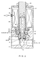
- Fig. 2 there is shown a nonenergized state of the valve, i.e., the solenoid coil 38 is deenergized, wherein the armature 18 is in a second position, and the sealing ring 14 is urged against the periphery of the orifice 12 by the spring 28.
- the first inlet port 4 is isolated from the second outlet port 8 and the third outlet port 32 while a fluid channel is provided from the second outlet port 8 to the outlet port 32 through the coaxial bore 20 in the armature 18 since the sealing member 24 is now spaced from the end plug 27.
- the fluid flow is effected through the bore 18 and the channels 36 on the armature 18 to provide a fluid channel between the second fluid port 8 and the third fluid port 32.
- the valve of the present invention When the valve of the present invention is deenergized, the first port 4 and the area surrounding the orifice 12 and the sealing ring 14 are exposed to the same pressure. Concurrently, the outlet port 35 is open to the second port 8 whereby the top and bottom of the armature 18 are exposed to the same low pressure whereby there is essentially no net pressure force acting on the armature 18 to resist its movement by the magnetic field produced by the energization of the solenoid 38. Additionally, any net pressure force due to a difference between the diameter of the rolling diaphragm 31 and the diameter of the sealing ring 14 can be eliminated by a suitable design thereof. When the valve is energized, the seal member 24 interrupts the flow path to the third port 35.
- the first port 4 is now opened directly to the outlet port 8 through the orifice 12 which allows a pressure balance as a result of the pressure acting on the top of the armature 18, inside the seal ring 14 and the bottom of the armature 18.
- the fluid flow along the outside of the armature 18 through the channels 36 serves to provide an initial measure of static lubrication to the armature 18 whereby to facilitate the initial movement of the armature in response to a magnetic field from the solenoid 38.
- the fluid flow through the channels 36 is interrupted upon the separation of the seal ring 14 from the orifice 12 to minimize any dashpot effect on the armature 18.
- the advantages of the design of the present invention are to provide a pressure balanced armature which is exposed to a lubricating fluid flow to greatly reduce the magnetic force required to actuate the armature in a simple design which is economical to manufacture and provides a configuration wherein all of the ports are in the valve body.
Landscapes
- Engineering & Computer Science (AREA)
- General Engineering & Computer Science (AREA)
- Mechanical Engineering (AREA)
- Magnetically Actuated Valves (AREA)
- Multiple-Way Valves (AREA)
Applications Claiming Priority (2)
| Application Number | Priority Date | Filing Date | Title |
|---|---|---|---|
| US06/718,767 US4582294A (en) | 1985-04-01 | 1985-04-01 | Three-way solenoid valve |
| US718767 | 1985-04-01 |
Publications (2)
| Publication Number | Publication Date |
|---|---|
| EP0196621A2 true EP0196621A2 (de) | 1986-10-08 |
| EP0196621A3 EP0196621A3 (de) | 1987-01-21 |
Family
ID=24887447
Family Applications (1)
| Application Number | Title | Priority Date | Filing Date |
|---|---|---|---|
| EP19860104173 Withdrawn EP0196621A3 (de) | 1985-04-01 | 1986-03-26 | Elektromagnetisches Ventil |
Country Status (4)
| Country | Link |
|---|---|
| US (1) | US4582294A (de) |
| EP (1) | EP0196621A3 (de) |
| JP (1) | JPS61233280A (de) |
| CA (1) | CA1241251A (de) |
Cited By (5)
| Publication number | Priority date | Publication date | Assignee | Title |
|---|---|---|---|---|
| DE4028506A1 (de) * | 1989-09-08 | 1991-03-21 | Automatic Switch Co | Proportionalstroemungsventil |
| WO1992013221A1 (en) * | 1991-01-16 | 1992-08-06 | Ab Mecman | A protective device for an exhaust channel of an electrically controlled pneumatic valve |
| WO1994011661A1 (en) * | 1992-11-10 | 1994-05-26 | Caterpillar Inc. | Solenoid valve assembly |
| GB2311359A (en) * | 1996-03-23 | 1997-09-24 | Lucas Ind Plc | Valve |
| EP3774413A4 (de) * | 2018-03-29 | 2022-01-05 | INFAC Corporation | Magnetventilanordnung für modusumschaltung in einem aufhängungssystem |
Families Citing this family (52)
| Publication number | Priority date | Publication date | Assignee | Title |
|---|---|---|---|---|
| US4889148A (en) * | 1986-10-29 | 1989-12-26 | The Coca-Cola Company | Flow control valve for a dispensing system |
| JPS63168377U (de) * | 1987-04-22 | 1988-11-02 | ||
| DE3814156A1 (de) * | 1988-04-27 | 1989-11-09 | Mesenich Gerhard | Pulsmoduliertes hydraulikventil |
| US4858956A (en) * | 1988-09-22 | 1989-08-22 | Siemens-Bendix Automotive Electronics L.P. | High pressure, fast response, pressure balanced, solenoid control valve |
| DE58909504D1 (de) * | 1989-01-28 | 1995-12-21 | Kuhnke Gmbh Kg H | Kraftausgeglichenes Hubventil. |
| US4901974A (en) * | 1989-05-11 | 1990-02-20 | Siemens-Bendix Automotive Electronics Limited | Canister purge solenoid valve |
| JPH0446277A (ja) * | 1990-06-13 | 1992-02-17 | Konan Denki Kk | ユニバーサル3ポート2位置電磁切換弁 |
| US5100102A (en) * | 1990-10-15 | 1992-03-31 | Ford Motor Company | Compact electronic fuel injector |
| DE4039766C1 (de) * | 1990-12-13 | 1992-06-04 | Fa. Carl Freudenberg, 6940 Weinheim, De | |
| US5116020A (en) * | 1991-02-13 | 1992-05-26 | Industrial Technology Research Institute | Diaphragmatic electromagnetic valve with leakage preventing convex ring |
| WO1993007382A1 (en) * | 1991-10-11 | 1993-04-15 | Caterpillar Inc. | Damped actuator and valve assembly for an electronically-controlled unit injector |
| EP0816733B1 (de) * | 1993-03-19 | 2001-07-04 | Cummins Engine Company, Inc. | Druckausgeglichenes Dreiwege-Magnetventil |
| EP0622573B1 (de) * | 1993-03-31 | 1996-06-12 | Cummins Engine Company, Inc. | Kompaktes Dreiwegeventil mit einem Dorn in einer Hülse |
| US5651501A (en) * | 1993-12-23 | 1997-07-29 | Caterpillar Inc. | Fluid damping of a valve assembly |
| US5518030A (en) * | 1994-12-12 | 1996-05-21 | Cummins Engine Company, Inc. | Three-way flow valve with variable drain orifice area |
| US5579741A (en) * | 1995-11-30 | 1996-12-03 | Siemens Electric Limited | Vapor purge valve having tapered bead armature seal |
| DE29713878U1 (de) * | 1997-08-04 | 1998-09-24 | Weh Gmbh, Verbindungstechnik, 89257 Illertissen | Schaltventil |
| US6199533B1 (en) | 1999-02-01 | 2001-03-13 | Cummins Engine Company, Inc. | Pilot valve controlled three-way fuel injection control valve assembly |
| US6045120A (en) * | 1998-01-13 | 2000-04-04 | Cummins Engine Company, Inc. | Flow balanced spill control valve |
| FR2784439B1 (fr) * | 1998-10-13 | 2000-12-29 | Peugeot | Agencement d'electrovanne susceptible d'etre fixee sur un support tel qu'un bloc hydraulique |
| EP1135639B1 (de) * | 1998-12-01 | 2003-07-02 | Rapa Rausch & Pausch Elektrotechnische Spezialfabrik Gmbh | Direkt gesteuertes magnetventil |
| US6158466A (en) * | 1999-01-14 | 2000-12-12 | Parker-Hannifin Corporation | Four-way flow reversing valve for reversible refrigeration cycles |
| US6217001B1 (en) * | 1999-06-29 | 2001-04-17 | Delphi Technologies, Inc. | Pressure balanced gas valve |
| US6435143B2 (en) * | 2000-03-01 | 2002-08-20 | Thomas J. Hollis | Three-way solenoid valve for actuating flow control valves in a temperature control system |
| US20030178530A1 (en) * | 2002-01-31 | 2003-09-25 | Marotta Scientific Controls, Inc. | System for decreasing the speed of a moving craft |
| JP2003269643A (ja) * | 2002-03-19 | 2003-09-25 | Nok Corp | ソレノイドバルブ |
| JP2004346993A (ja) * | 2003-05-21 | 2004-12-09 | Matsushita Electric Ind Co Ltd | 遮断弁とその組立方法 |
| US6935612B2 (en) * | 2003-05-21 | 2005-08-30 | Airsep Corporation | Solenoid valve |
| US6907897B2 (en) * | 2003-06-26 | 2005-06-21 | Planar Systems, Inc. | Diaphragm valve for high-temperature precursor supply in atomic layer deposition |
| US7021330B2 (en) | 2003-06-26 | 2006-04-04 | Planar Systems, Inc. | Diaphragm valve with reliability enhancements for atomic layer deposition |
| US6941963B2 (en) * | 2003-06-26 | 2005-09-13 | Planar Systems, Inc. | High-speed diaphragm valve for atomic layer deposition |
| US7939239B2 (en) | 2004-05-20 | 2011-05-10 | LaserLock Technologies Inc. | Illumination sources and subjects having distinctly matched and mismatched narrow spectral bands |
| US7458395B2 (en) * | 2004-06-07 | 2008-12-02 | Borgwarner Inc. | Low leak poppet solenoid |
| US7913679B2 (en) * | 2004-06-10 | 2011-03-29 | Kee Action Sports I Llc | Valve assembly for a compressed gas gun |
| US8302390B2 (en) * | 2004-09-28 | 2012-11-06 | Continental Automotive Systems Us, Inc. | Turbo control valve utilizing a permanent magnet |
| JP2006153218A (ja) * | 2004-11-30 | 2006-06-15 | Keihin Corp | 燃料電池用電磁弁 |
| WO2006083783A1 (en) * | 2005-01-31 | 2006-08-10 | Swagelok Company | Flow control device |
| JP2006349142A (ja) * | 2005-06-20 | 2006-12-28 | Borgwarner Inc | 低漏洩ポペット電磁弁 |
| US7849876B2 (en) * | 2006-08-17 | 2010-12-14 | Parker-Hannifin Corporation | Valve assembly with sealing force |
| US8430377B2 (en) * | 2008-03-26 | 2013-04-30 | Parker-Hannifin Corporation | Valve |
| CN102292581A (zh) * | 2009-01-27 | 2011-12-21 | 博格华纳公司 | 带有固有的粘性阻尼作用的、开放端可变放泄的螺线管(vbs)阀门 |
| DE102009041446A1 (de) * | 2009-09-16 | 2011-03-24 | Svm Schultz Verwaltungs-Gmbh & Co. Kg | Elektromagnet |
| US9068666B2 (en) * | 2010-05-10 | 2015-06-30 | Borgwarner Inc. | Electronic coolant valve with integral actuator mechanism |
| US8733732B2 (en) * | 2010-05-24 | 2014-05-27 | Eaton Corporation | Pressurized o-ring pole piece seal for a manifold |
| WO2014130573A1 (en) | 2013-02-19 | 2014-08-28 | LaserLock Technologies Inc. | Characteristic verification system |
| WO2014153175A1 (en) | 2013-03-14 | 2014-09-25 | LaserLock Technologies Inc. | Secure medium with detectable and authentication elements |
| US9377126B2 (en) * | 2013-07-22 | 2016-06-28 | Schaeffler Technologies AG & Co. KG | Control valve with integral pressure switch |
| CN104565497B (zh) | 2013-10-23 | 2019-02-05 | 德昌电机(深圳)有限公司 | 电磁阀 |
| MY188606A (en) * | 2015-07-09 | 2021-12-22 | Vistadeltek Llc | Control plate in a valve |
| US10993546B2 (en) | 2016-10-28 | 2021-05-04 | Sleep Number Corporation | Noise reducing plunger |
| EP3839308A1 (de) | 2019-12-20 | 2021-06-23 | Siemens Schweiz AG | Expansionsventil |
| US11832728B2 (en) | 2021-08-24 | 2023-12-05 | Sleep Number Corporation | Controlling vibration transmission within inflation assemblies |
Family Cites Families (8)
| Publication number | Priority date | Publication date | Assignee | Title |
|---|---|---|---|---|
| US2601989A (en) * | 1947-10-08 | 1952-07-01 | Powers Regulator Co | Balanced three-way valve |
| US2886063A (en) * | 1957-08-12 | 1959-05-12 | Gen Controls Co | Valve structure |
| US3071147A (en) * | 1960-01-11 | 1963-01-01 | Bendix Westinghouse Automotive | Fluid pressure feed or reducing valve |
| US3007672A (en) * | 1960-12-21 | 1961-11-07 | Union Tank Car Co | Electromagnetically operated valve |
| DE2826973A1 (de) * | 1978-06-20 | 1980-01-17 | Knorr Bremse Gmbh | Magnetventil |
| US4376447A (en) * | 1979-08-20 | 1983-03-15 | Umc Industries, Inc. | Hot water valve |
| DE3111716A1 (de) * | 1981-03-25 | 1982-10-07 | Joachim Dipl.-Ing. 7551 Bischweier Scholz | Elektromagnetisch betaetigbares doppelsitzventil |
| JPS58178077A (ja) * | 1982-04-08 | 1983-10-18 | Hitachi Ltd | 圧力制御弁 |
-
1985
- 1985-04-01 US US06/718,767 patent/US4582294A/en not_active Expired - Lifetime
-
1986
- 1986-03-26 EP EP19860104173 patent/EP0196621A3/de not_active Withdrawn
- 1986-03-27 CA CA000505271A patent/CA1241251A/en not_active Expired
- 1986-04-01 JP JP61072664A patent/JPS61233280A/ja active Pending
Cited By (7)
| Publication number | Priority date | Publication date | Assignee | Title |
|---|---|---|---|---|
| DE4028506A1 (de) * | 1989-09-08 | 1991-03-21 | Automatic Switch Co | Proportionalstroemungsventil |
| DE4028506C2 (de) * | 1989-09-08 | 1999-07-08 | Automatic Switch Co | Proportionalströmungsventil |
| WO1992013221A1 (en) * | 1991-01-16 | 1992-08-06 | Ab Mecman | A protective device for an exhaust channel of an electrically controlled pneumatic valve |
| WO1994011661A1 (en) * | 1992-11-10 | 1994-05-26 | Caterpillar Inc. | Solenoid valve assembly |
| US5564676A (en) * | 1992-11-10 | 1996-10-15 | Fluid Power Industries, Inc. | Solenoid valve assembly |
| GB2311359A (en) * | 1996-03-23 | 1997-09-24 | Lucas Ind Plc | Valve |
| EP3774413A4 (de) * | 2018-03-29 | 2022-01-05 | INFAC Corporation | Magnetventilanordnung für modusumschaltung in einem aufhängungssystem |
Also Published As
| Publication number | Publication date |
|---|---|
| JPS61233280A (ja) | 1986-10-17 |
| EP0196621A3 (de) | 1987-01-21 |
| CA1241251A (en) | 1988-08-30 |
| US4582294A (en) | 1986-04-15 |
Similar Documents
| Publication | Publication Date | Title |
|---|---|---|
| EP0196621A2 (de) | Elektromagnetisches Ventil | |
| US4546955A (en) | Two-stage solenoid valve | |
| US4624282A (en) | Two-stage solenoid valve | |
| US5301921A (en) | Proportional electropneumatic solenoid-controlled valve | |
| US4253493A (en) | Actuators | |
| US4513780A (en) | Solenoid valve | |
| US4251051A (en) | Solenoid structure having a relatively unrestrained generally flat armature member | |
| US6290203B1 (en) | Pilot operated valve assembly | |
| GB1603036A (en) | Pressure operated pilot controlled shut-off valve | |
| US5064166A (en) | Solenoid valve with high flow capacity and low energy consumption | |
| EP0795706A1 (de) | Allgemeines Magnetabsperrventil | |
| KR970075616A (ko) | 유량 제어 밸브 | |
| US4501298A (en) | Solenoid actuated valve device | |
| CA1216494A (en) | Electrically actuated valve assembly | |
| US3410308A (en) | Moving coil electrohydraulic servovalve | |
| US4846439A (en) | Electromagnetic valve assembly | |
| US20050145813A1 (en) | Solenoid valve assembly | |
| US4694270A (en) | Electromagnetic proportional actuator | |
| US20060124880A1 (en) | Magnetically-actuated manually-operated isolation valve | |
| US3908700A (en) | Solenoid valve | |
| US4933516A (en) | Poppet valve flow switch | |
| JPH0725492Y2 (ja) | プランジャ型ソレノイド弁 | |
| JP2551917Y2 (ja) | 電磁弁 | |
| JPH0720461Y2 (ja) | 電磁弁 | |
| GB1586044A (en) | Electro-magnetically operable valves |
Legal Events
| Date | Code | Title | Description |
|---|---|---|---|
| PUAI | Public reference made under article 153(3) epc to a published international application that has entered the european phase |
Free format text: ORIGINAL CODE: 0009012 |
|
| AK | Designated contracting states |
Kind code of ref document: A2 Designated state(s): CH DE FR GB IT LI NL SE |
|
| PUAL | Search report despatched |
Free format text: ORIGINAL CODE: 0009013 |
|
| AK | Designated contracting states |
Kind code of ref document: A3 Designated state(s): CH DE FR GB IT LI NL SE |
|
| STAA | Information on the status of an ep patent application or granted ep patent |
Free format text: STATUS: THE APPLICATION IS DEEMED TO BE WITHDRAWN |
|
| 18D | Application deemed to be withdrawn |
Effective date: 19870722 |
|
| RIN1 | Information on inventor provided before grant (corrected) |
Inventor name: FARGO, RICHARD N. |