EP0196624A2 - Petit poste électrique - Google Patents
Petit poste électrique Download PDFInfo
- Publication number
- EP0196624A2 EP0196624A2 EP86104196A EP86104196A EP0196624A2 EP 0196624 A2 EP0196624 A2 EP 0196624A2 EP 86104196 A EP86104196 A EP 86104196A EP 86104196 A EP86104196 A EP 86104196A EP 0196624 A2 EP0196624 A2 EP 0196624A2
- Authority
- EP
- European Patent Office
- Prior art keywords
- framework
- small station
- station according
- concrete
- rails
- Prior art date
- Legal status (The legal status is an assumption and is not a legal conclusion. Google has not performed a legal analysis and makes no representation as to the accuracy of the status listed.)
- Granted
Links
Images


Classifications
-
- H—ELECTRICITY
- H02—GENERATION; CONVERSION OR DISTRIBUTION OF ELECTRIC POWER
- H02B—BOARDS, SUBSTATIONS OR SWITCHING ARRANGEMENTS FOR THE SUPPLY OR DISTRIBUTION OF ELECTRIC POWER
- H02B13/00—Arrangement of switchgear in which switches are enclosed in, or structurally associated with, a casing, e.g. cubicle
- H02B13/02—Arrangement of switchgear in which switches are enclosed in, or structurally associated with, a casing, e.g. cubicle with metal casing
- H02B13/025—Safety arrangements, e.g. in case of excessive pressure or fire due to electrical defect
-
- H—ELECTRICITY
- H02—GENERATION; CONVERSION OR DISTRIBUTION OF ELECTRIC POWER
- H02B—BOARDS, SUBSTATIONS OR SWITCHING ARRANGEMENTS FOR THE SUPPLY OR DISTRIBUTION OF ELECTRIC POWER
- H02B7/00—Enclosed substations, e.g. compact substations
- H02B7/06—Distribution substations, e.g. for urban network
Definitions
- The. The invention relates to a small station according to the preamble of claim 1.
- Smaller electrical network stations which are particularly suitable for installation at consumer centers, have long been designed as non-accessible compact stations, so-called small stations.
- Known small stations have a housing made of lightweight concrete, which is combined with weatherproof sheet steel parts for the ventilation walls, the roof and the doors. They are relatively expensive to manufacture, have a high weight and require special precautions for the safe derivation of Explo pressure waves from inside the building to the outside environment.
- the concrete housing of these small stations is increasingly rejected because it is aesthetically disturbing in many places. Recent experience has shown that concrete is not an indestructible material, as has long been assumed.
- Station buildings in metal or plastic construction are already known, which have a frame made of C or L profiles. However, these buildings have too little stability, so that they have not proven themselves as potentially explosive network station buildings.
- the present invention is therefore based on the object to develop a new design principle for such small stations, which takes into account the above-mentioned new requirements for small stations and leads to more stable, cheaper, versatile stations, the exterior of which can be adapted to the respective installation site without additional expenditure.
- the body of the building from the framework has many advantages over conventional concrete buildings: it has a much lighter weight and a high inherent quality rigidity, the cladding and infill of the framework can be adapted to the respective purpose and location quickly and inexpensively. Likewise, the outside dimensions of the station and the division of its interior can be varied without difficulty, the attachment of the partition walls, devices and other installations does not require any additional precautions, the ratio of inside dimensions to outside dimensions is extremely favorable.
- the building body of the small station according to the invention has a considerably increased stability due to the square tubes provided, which are used simultaneously for ventilation and pressure relief of the interior of the building, so that the facilities provided for this in the known station buildings can be saved .
- the base frame as well as the frame above are as all around and. -Exhaust air trained.
- the outer cladding of the framework preferably consists of aluminum profiles, profiled aluminum sheet, sheets, plastic concrete, glass fiber concrete. or wooden panels.
- plastering as external cladding on the framework clad with sheet metal or with light concrete, concrete or synthetic resin concrete. In the latter case, reinforcements of structural steel mesh are appropriate.
- Doors for TransfDrmatoren and 'ventilation on the two longitudinal walls can be omitted in this small station, since the roof is designed to be foldable, so that access to the transformer is possible from above.
- the roof can be constructed in one or more parts in accordance with the detailed functions of the network stations. The hinged If necessary, the roof over the transformer must be fitted with a lower apron. By eliminating the side ventilation doors, a more economical, visually clearer solution with less need for retention areas around the station is possible.
- the framework of the small station according to the invention therefore fulfills several functions at the same time: it has a static task to ensure the inherent rigidity of the station, it serves as a support for the installed devices, it guarantees safe earthing at every location of the station, it ensures safe ventilation and pressure relief , it serves as a cladding support for any external cladding and it allows cross-connections within the station for fastening partitions, units and MV and LV cables.
- the invention is based on. several embodiments shown in the drawing described and explained.
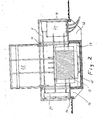
- the framework according to FIG. 1 of a small station consists of vertically extending square tubes 10 and horizontally extending C-profile rails 11, which in turn are connected by transverse C-profile rails 12 for the transverse stiffening of the framework.
- the top and bottom horizontal rails 13 and 14, which belong to the outer frame of the framework, are also square tubes, which have punched or cutouts or at least partially consist of perforated sheet or steel mesh, so that through them the ventilation of the interior of the small station can be performed.
- the upper transverse square tubes 10, which are shown in the drawing in the removed state and can be plugged onto the rest of the framework, are part of the roof closing the small station upwards, which is shown in the exemplary embodiments described later.
- the framework is fastened on a base frame 15, which in this exemplary embodiment is in the form of a floor pan, which is divided into three segments: a front segment 16, over which the low-voltage space of the small station extends, a middle segment 17 for the Transformer room with a closed trough for collecting the transformer oil and a rear segment 18, above which the high-voltage or medium-voltage room is arranged.
- the latching of the square tubes 10 depends on the width of these three segments 16 to 18, so that the roof of the small station can also correspond to these segment widths.
- the base frame 15 is advantageously cast from concrete; However, it can also be made of plastic or sheet metal if it is important to reduce the weight of the small station to a minimum.
- the C-profile rails 11 and 12 of the framework expediently serve at the same time as fastening rails for partition walls, MV and LV switchgear and other installations of the small station and offer the possibility of secure earthing in all areas of the small station.
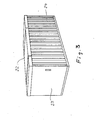
- the small station is shown in the installed state with the Dabh unfolded above the transformer room in a longitudinal section.
- the transformer With 19 the transformer, with 20 the medium voltage switchgear and with 21 the low voltage switchgear.
- the latter are installed in the upper framework and can be transported with the framework as a chassis.
- the roof 22 above the transformer room 17 is pivotally mounted on the vertical or horizontal square tubes 10.
- FIG. 3 shows an overall perspective view of the part of the small station protruding from the earth, the outer walls of the small station being clad by aluminum doors 23 or aluminum sheets, aluminum profiles or sheet trapezoidal profiles 24.
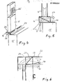
- FIG. 4 shows a square tube 10 which runs vertically in the framework and which, together with the lowest horizontally extending square tube 14, forms the ventilation system for the small station.
- the vertical square tube 10 has openings 25 in its upper region which point into the interior of the small station.
- the lower end of the square tube 10 is welded to the horizontally extending square tube 14 in such a way that an unimpeded air flow through the interior of the two tubes is ensured, as indicated by the dashed arrow in FIG. 5.
- the horizontally extending square tube 14 projects with its lower surface beyond the base frame 15 of the small station to the outside, so that the supply and exhaust air can enter or exit all around through the openings 26 provided in this partial area of the base of the square tube 14.
- openings 27 are also provided in the side surface of the square tube pointing into the station interior, through which primarily the fresh air can flow into the small station, as indicated by the arrow in FIG. 5.
- Optimal ventilation and cooling of the small station is achieved by supplying the fresh air in the lower area of the station interior and removing the heated air in the upper area of the station interior.
- FIGS. 6 and 9 An equivalent venting device in the upper area of the small station is shown in FIGS. 6 and 9 poses.
- the pipe running horizontally directly under the roof 22 consists of a perforated square pipe 13 into which a diagonally running perforated plate 29 is also inserted.
- the exhaust air from the small station, as indicated by the arrow in FIG. 6, is directed to the floor through the roof 22 which projects beyond the side walls of the station and is angled downwards.
- swiveling fins 40 automatically close the round vent and thus only allow the pressure wave to travel through the aluminum hollow profiles or channels between the sheets and the profile sheet, so that the hot gases cool down greatly on the extended path marked with an arrow 41 and can only exit in the lower area of the station close to the ground.
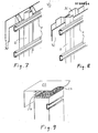
- FIGS. 7 and 8 show two exemplary embodiments of the outer cladding of the framework with flat metal sheets 32 and trapezoidal sheets 31 or with aluminum hollow profiles 30 with integrated supply and exhaust air or pressure relief channels which are protected against arcing.
- a flat .Table 32 made of aluminum, sheet steel or a plastic is first attached.
- the outer cladding panels 31 are then fastened to this panel 32, so that ventilation ducts or pressure relief ducts are formed as in the case of the aluminum hollow profiles 30.
- the inflow or outflow takes place in that the interior trim parts are designed to be lower in height than the exterior ones.
- the ventilation ducts between the plates 32 and 31 ensure that and exhaust air for the interior of the small station, depending on the arrangement of the outer cladding panels 30 and 31 so that the supply air enters the ventilation duct at the bottom and is fed to the inside of the station at the top (FIG. 10) or vice versa (FIG. 11).
- the pressure wave escapes after the all-round ventilation is closed either through the supply air slots in the lower area of the station or, to a greater extent because of the buoyancy of hot gases, through the upper inlet openings of the ventilation ducts.
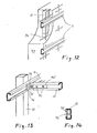
- the framework part according to FIG. 12 is filled with concrete 33, the strength of which is increased by a reinforcement 34.
- the vertical square tubes 10 and the horizontal C-profile rails 11 are also in the concrete wall 33.
- the outside of the small station has a plastering, not shown in the drawing.
- This infill of the framework with concrete represents an alternative to the cladding solutions of the small station with sheet metal plates according to Figures 7 and 8.
- both solutions can also be combined, for example in such a way that the rear wall placed in an embankment and the side walls with concrete infill. while the exposed front wall is clad with profile panels.
- Figure 13 shows an expedient way of connecting two mutually perpendicular C-profile rails 11 and 12 in the framework.
- the connection is made by a tie rod which has two sheet metal strips 35 and 36 arranged at right angles to one another, which are non-positively connected to one another by a hammer or hook-head screw 37 with a lock nut 38.
- the sheet metal strip 35 is inserted into the C profile rail 12 and fixed there with pressure screws 39, the head of which does not protrude beyond the C profile of the rail 12.
- the hammer or hook head screw 37 is inserted into the C-profile of the other rail 11 and fixed there by means of the lock nut.
Landscapes
- Engineering & Computer Science (AREA)
- Power Engineering (AREA)
- Building Environments (AREA)
- Vehicle Body Suspensions (AREA)
- Input Circuits Of Receivers And Coupling Of Receivers And Audio Equipment (AREA)
- Magnetic Resonance Imaging Apparatus (AREA)
- Transplanting Machines (AREA)
- Foundations (AREA)
Priority Applications (1)
| Application Number | Priority Date | Filing Date | Title |
|---|---|---|---|
| AT86104196T ATE53460T1 (de) | 1985-04-02 | 1986-03-26 | Kleinstation. |
Applications Claiming Priority (2)
| Application Number | Priority Date | Filing Date | Title |
|---|---|---|---|
| DE3511962 | 1985-04-02 | ||
| DE19853511962 DE3511962A1 (de) | 1985-04-02 | 1985-04-02 | Kleinstation |
Publications (3)
| Publication Number | Publication Date |
|---|---|
| EP0196624A2 true EP0196624A2 (fr) | 1986-10-08 |
| EP0196624A3 EP0196624A3 (en) | 1988-07-20 |
| EP0196624B1 EP0196624B1 (fr) | 1990-06-06 |
Family
ID=6267058
Family Applications (1)
| Application Number | Title | Priority Date | Filing Date |
|---|---|---|---|
| EP86104196A Expired - Lifetime EP0196624B1 (fr) | 1985-04-02 | 1986-03-26 | Petit poste électrique |
Country Status (3)
| Country | Link |
|---|---|
| EP (1) | EP0196624B1 (fr) |
| AT (1) | ATE53460T1 (fr) |
| DE (2) | DE3511962A1 (fr) |
Cited By (4)
| Publication number | Priority date | Publication date | Assignee | Title |
|---|---|---|---|---|
| EP0563436A1 (fr) * | 1992-03-31 | 1993-10-06 | Betonbau GmbH | Bâtiment transportable et sa méthode de construction |
| CN105909005A (zh) * | 2016-04-14 | 2016-08-31 | 国家电网公司 | 一种用于高寒地区特(超)高压变压器安装的保温棚及其搭建方法 |
| CN113251246A (zh) * | 2021-06-21 | 2021-08-13 | 西安西热锅炉环保工程有限公司 | 一种燃煤耦合污泥发电联合设备组支撑装置 |
| US20240291247A1 (en) * | 2021-07-05 | 2024-08-29 | Unareti S.P.A | Electrical transformation substation |
Families Citing this family (1)
| Publication number | Priority date | Publication date | Assignee | Title |
|---|---|---|---|---|
| DE102024118463A1 (de) | 2024-06-28 | 2025-12-31 | Holzbau Dawen GmbH | Funktionsgebäude für Stromschaltanlagen |
Family Cites Families (3)
| Publication number | Priority date | Publication date | Assignee | Title |
|---|---|---|---|---|
| FR593668A (fr) * | 1925-02-19 | 1925-08-28 | Cabine pour transformateurs électriques et autres usages | |
| FR1428544A (fr) * | 1964-12-31 | 1966-02-18 | Entpr Generale D Installations | Nouveau poste de transformation |
| AT336227B (de) * | 1974-06-24 | 1977-04-25 | Vmw Ranshofen Berndorf Ag | Trafostation, insbesondere turmtrafostation in leichtbauweise aus metall |
-
1985
- 1985-04-02 DE DE19853511962 patent/DE3511962A1/de not_active Withdrawn
-
1986
- 1986-03-26 DE DE8686104196T patent/DE3671814D1/de not_active Expired - Lifetime
- 1986-03-26 AT AT86104196T patent/ATE53460T1/de not_active IP Right Cessation
- 1986-03-26 EP EP86104196A patent/EP0196624B1/fr not_active Expired - Lifetime
Cited By (4)
| Publication number | Priority date | Publication date | Assignee | Title |
|---|---|---|---|---|
| EP0563436A1 (fr) * | 1992-03-31 | 1993-10-06 | Betonbau GmbH | Bâtiment transportable et sa méthode de construction |
| CN105909005A (zh) * | 2016-04-14 | 2016-08-31 | 国家电网公司 | 一种用于高寒地区特(超)高压变压器安装的保温棚及其搭建方法 |
| CN113251246A (zh) * | 2021-06-21 | 2021-08-13 | 西安西热锅炉环保工程有限公司 | 一种燃煤耦合污泥发电联合设备组支撑装置 |
| US20240291247A1 (en) * | 2021-07-05 | 2024-08-29 | Unareti S.P.A | Electrical transformation substation |
Also Published As
| Publication number | Publication date |
|---|---|
| EP0196624B1 (fr) | 1990-06-06 |
| DE3511962A1 (de) | 1986-10-09 |
| ATE53460T1 (de) | 1990-06-15 |
| DE3671814D1 (de) | 1990-07-12 |
| EP0196624A3 (en) | 1988-07-20 |
Similar Documents
| Publication | Publication Date | Title |
|---|---|---|
| DE3408390A1 (de) | Raumzelle | |
| EP0563436A1 (fr) | Bâtiment transportable et sa méthode de construction | |
| EP0639677B1 (fr) | Bâtiment composé par des modules de cellules préfabriquées | |
| DE2654002A1 (de) | Vorgefertigte gebaeudeeinheit fuer mehrfachverwendung | |
| DE4020962A1 (de) | Raumzelle | |
| EP0196624B1 (fr) | Petit poste électrique | |
| DE3103581A1 (de) | Einheitsfundament fuer auf schiffsdecks anzuordnende geraete | |
| DE102019121346B4 (de) | Deckenmodul zum Aufbau eines Reinraums | |
| EP0209027B1 (fr) | Station de transformation transportable | |
| DE8509797U1 (de) | Kleinstation | |
| DE3024437A1 (de) | Fertigbausystem fuer schutzraeume | |
| EP0566860A2 (fr) | Cellule-close en béton armé antidéflagrante, en particulier cellule-close-poste de transformation en béton armé | |
| EP0106297A2 (fr) | Elément de construction pour la fabrication de murs en béton et mur de bâtiment fabriqué avec celui-ci | |
| DE2657614A1 (de) | Raumkonstruktion zur bildung von bauwerken mit einer oder mehreren etagen | |
| DE7924725U1 (de) | Stuetz- und traggeruest fuer eine aus einzelnen rasterelementen zusammensetzbare schallschutzverkleidung fuer maschinen, insbesondere schallschutzkapselung und -kabine | |
| DE2540915C3 (de) | Außenwandkonstruktion für Bauwerke | |
| DE10019262C2 (de) | Zerlegbare, wiederaufbaubare Raumzelle | |
| DE20215395U1 (de) | Transportable Raumzelle zum Schutz einer Senderanlage oder anderer elektronischer Geräte | |
| DE1931427C3 (de) | Wandkonstruktion für Bauwerke | |
| DE9405471U1 (de) | Reststoff-/Abfall-Sammelstation | |
| DE3621893A1 (de) | Gittertraeger aus metall fuer den geruestbau und die errichtung weitgespannter temporaerer ueberdachungen mit mind. drei gurten in einer ebene | |
| DE2207955A1 (de) | Stahlkonstruktion mit raumzellen | |
| DE19639471A1 (de) | Verfahren zum Sanieren von Wohngebäuden, die in Plattenbauweise hergestellt sind | |
| DE3145647A1 (de) | Vorgehaengte fassade | |
| DE20212484U1 (de) | Transformatorenstation |
Legal Events
| Date | Code | Title | Description |
|---|---|---|---|
| PUAI | Public reference made under article 153(3) epc to a published international application that has entered the european phase |
Free format text: ORIGINAL CODE: 0009012 |
|
| AK | Designated contracting states |
Kind code of ref document: A2 Designated state(s): AT BE CH DE FR LI |
|
| PUAL | Search report despatched |
Free format text: ORIGINAL CODE: 0009013 |
|
| AK | Designated contracting states |
Kind code of ref document: A3 Designated state(s): AT BE CH DE FR LI |
|
| 17P | Request for examination filed |
Effective date: 19880611 |
|
| 17Q | First examination report despatched |
Effective date: 19891103 |
|
| GRAA | (expected) grant |
Free format text: ORIGINAL CODE: 0009210 |
|
| AK | Designated contracting states |
Kind code of ref document: B1 Designated state(s): AT BE CH DE FR LI |
|
| REF | Corresponds to: |
Ref document number: 53460 Country of ref document: AT Date of ref document: 19900615 Kind code of ref document: T |
|
| REF | Corresponds to: |
Ref document number: 3671814 Country of ref document: DE Date of ref document: 19900712 |
|
| ET | Fr: translation filed | ||
| PLBE | No opposition filed within time limit |
Free format text: ORIGINAL CODE: 0009261 |
|
| STAA | Information on the status of an ep patent application or granted ep patent |
Free format text: STATUS: NO OPPOSITION FILED WITHIN TIME LIMIT |
|
| 26N | No opposition filed | ||
| PGFP | Annual fee paid to national office [announced via postgrant information from national office to epo] |
Ref country code: FR Payment date: 19950302 Year of fee payment: 10 |
|
| PGFP | Annual fee paid to national office [announced via postgrant information from national office to epo] |
Ref country code: BE Payment date: 19950309 Year of fee payment: 10 Ref country code: AT Payment date: 19950309 Year of fee payment: 10 |
|
| PGFP | Annual fee paid to national office [announced via postgrant information from national office to epo] |
Ref country code: DE Payment date: 19950411 Year of fee payment: 10 |
|
| PGFP | Annual fee paid to national office [announced via postgrant information from national office to epo] |
Ref country code: CH Payment date: 19950509 Year of fee payment: 10 |
|
| PG25 | Lapsed in a contracting state [announced via postgrant information from national office to epo] |
Ref country code: AT Effective date: 19960326 |
|
| PG25 | Lapsed in a contracting state [announced via postgrant information from national office to epo] |
Ref country code: LI Effective date: 19960331 Ref country code: CH Effective date: 19960331 Ref country code: BE Effective date: 19960331 |
|
| BERE | Be: lapsed |
Owner name: BETONBAU G.M.B.H. Effective date: 19960331 |
|
| REG | Reference to a national code |
Ref country code: CH Ref legal event code: PL |
|
| PG25 | Lapsed in a contracting state [announced via postgrant information from national office to epo] |
Ref country code: FR Effective date: 19961129 |
|
| PG25 | Lapsed in a contracting state [announced via postgrant information from national office to epo] |
Ref country code: DE Effective date: 19961203 |
|
| REG | Reference to a national code |
Ref country code: FR Ref legal event code: ST |