EP0196868A2 - Frequenzsynthetisierer mit Linearisierung des Modulationsganges - Google Patents
Frequenzsynthetisierer mit Linearisierung des Modulationsganges Download PDFInfo
- Publication number
- EP0196868A2 EP0196868A2 EP86302228A EP86302228A EP0196868A2 EP 0196868 A2 EP0196868 A2 EP 0196868A2 EP 86302228 A EP86302228 A EP 86302228A EP 86302228 A EP86302228 A EP 86302228A EP 0196868 A2 EP0196868 A2 EP 0196868A2
- Authority
- EP
- European Patent Office
- Prior art keywords
- frequency
- response
- control signal
- synthesized
- generating
- Prior art date
- Legal status (The legal status is an assumption and is not a legal conclusion. Google has not performed a legal analysis and makes no representation as to the accuracy of the status listed.)
- Withdrawn
Links
Images


Classifications
-
- H—ELECTRICITY
- H03—ELECTRONIC CIRCUITRY
- H03C—MODULATION
- H03C3/00—Angle modulation
- H03C3/02—Details
- H03C3/09—Modifications of modulator for regulating the mean frequency
- H03C3/0908—Modifications of modulator for regulating the mean frequency using a phase locked loop
- H03C3/0966—Modifications of modulator for regulating the mean frequency using a phase locked loop modulating the reference clock
-
- H—ELECTRICITY
- H03—ELECTRONIC CIRCUITRY
- H03L—AUTOMATIC CONTROL, STARTING, SYNCHRONISATION OR STABILISATION OF GENERATORS OF ELECTRONIC OSCILLATIONS OR PULSES
- H03L7/00—Automatic control of frequency or phase; Synchronisation
- H03L7/06—Automatic control of frequency or phase; Synchronisation using a reference signal applied to a frequency- or phase-locked loop
- H03L7/08—Details of the phase-locked loop
- H03L7/085—Details of the phase-locked loop concerning mainly the frequency- or phase-detection arrangement including the filtering or amplification of its output signal
- H03L7/089—Details of the phase-locked loop concerning mainly the frequency- or phase-detection arrangement including the filtering or amplification of its output signal the phase or frequency detector generating up-down pulses
- H03L7/0891—Details of the phase-locked loop concerning mainly the frequency- or phase-detection arrangement including the filtering or amplification of its output signal the phase or frequency detector generating up-down pulses the up-down pulses controlling source and sink current generators, e.g. a charge pump
- H03L7/0895—Details of the current generators
- H03L7/0898—Details of the current generators the source or sink current values being variable
-
- H—ELECTRICITY
- H03—ELECTRONIC CIRCUITRY
- H03L—AUTOMATIC CONTROL, STARTING, SYNCHRONISATION OR STABILISATION OF GENERATORS OF ELECTRONIC OSCILLATIONS OR PULSES
- H03L7/00—Automatic control of frequency or phase; Synchronisation
- H03L7/06—Automatic control of frequency or phase; Synchronisation using a reference signal applied to a frequency- or phase-locked loop
- H03L7/16—Indirect frequency synthesis, i.e. generating a desired one of a number of predetermined frequencies using a frequency- or phase-locked loop
- H03L7/18—Indirect frequency synthesis, i.e. generating a desired one of a number of predetermined frequencies using a frequency- or phase-locked loop using a frequency divider or counter in the loop
- H03L7/183—Indirect frequency synthesis, i.e. generating a desired one of a number of predetermined frequencies using a frequency- or phase-locked loop using a frequency divider or counter in the loop a time difference being used for locking the loop, the counter counting between fixed numbers or the frequency divider dividing by a fixed number
-
- H—ELECTRICITY
- H03—ELECTRONIC CIRCUITRY
- H03C—MODULATION
- H03C2200/00—Indexing scheme relating to details of modulators or modulation methods covered by H03C
- H03C2200/0037—Functional aspects of modulators
- H03C2200/0079—Measures to linearise modulation or reduce distortion of modulation characteristics
- H03C2200/0083—Predistortion of input modulating signal to obtain a linear modulation characteristic
Definitions
- the invention disclosed herein is, generally, concerned with phase-locked loop frequency synthesizers.
- this invention relates to flat modulation response, wide bandwidth frequency synthesizers.
- VCOs Voltage Controlled Oscillators
- the instant invention solves the problem by flattening The modulation response by providing constant loop gain through compensation of the nonlinear VCO gain with a substantially raciprocal or multiplicatively inverse gain.
- This invention represents a measurable advance over the prior art and over this technical field by providing a constant gain, wide bandwidth frequency synthesizer.
- Another object of the present invention is to provide a relatively low cost, constant gain, wideband frequency synthesizer.
- the ultimate object is to provide a relatively low cost, constant gain, wide bandwidth frequency synthesizer having a relatively flat modulation response over the entire VCO steering line voltage range.
- a method of substantially flattening the modulation response in a frequency synthesizer includes the steps of generating a synthesized frequency in response to a filtered control signal; scaling the synthesized frequency with a scalar; generating a control signal, having a response substantially the reciprocal of the frequency generation response, and indicative of the phase relationship between a reference frequency and the scaled, synthesized frequency; and filtering the control signal, whereby the interaction of the phase relationship control signal response and the frequency generation response approximates a flat modulation response.
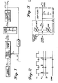
- digital frequency synthesizers commonly employ standard phase-locked loop circuitry wherein a Voltage Controlled Oscillator (VCO) signal F 0 is divided by a loop divisor N. The output of the loop divisor Fn is compared to a reference frequency signal F r in a phase detector.
- a charge pump generates a charging current I ⁇ whose duration is proportional to the phase difference detected.
- the charging current I ⁇ is utilized to charge capacitive elements C in loop filter thereby developing a steering line control voltage V s for the Voltage Controlled Oscillator (VCO).
- the filter assists in maintaining the synthesized frequency Fo by reducing its sensitivity to sporadic disturbances or perturbations.
- phase-locked loop operates to acquire, and then maintain, the Voltage Controlled Oscillator (VCO) frequency as an integral multiple (N) of a reference frequency F r .
- VCO Voltage Controlled Oscillator
- the synthesized frequency F O is scaled by a divisor N.
- the divisor N is chosen to correspond to the desired synthesized frequency.
- the scaled synthesized frequency F n is compared to a reference frequency signal Fr in a phase detector.
- the reference frequency F r can be provided by any suitable frequency generator.
- the phase detector generates signals indicative of the phase relationship between the reference frequency F r and the scaled, synthesized frequency F n .
- the phase detector is a digital, three-state phase detector and charge pump of the type generally described in Motorola Semiconductor P roducts' M C4344°MC4044 literature, 1972.
- a pulse whose duration is proportional to the phase difference, is produced when the synthesized frequency F O must be brought up from its current frequency while a pulse of similar duration is produced when the synthesized frequency F o must be brought down from its current value.
- a steady state signal is produced when the synthesized frequency F O is at its desired value and no phase difference exists.
- a charge pump generates a charging or discharging current I ⁇ and supplies it to the capacitive elements C of the loop filter in response to the up and down pulses received from the digital phase detector.
- This current control signal I ⁇ charges or discharges the capacitive elements C in the loop filter thereby generating a control voltage V s for the Voltage Controlled Oscillator (VCO).
- VCO Voltage Controlled Oscillator
- resistive R and capacitive C elements in the loop filter provide a filtering time constant by which sporadic disturbances or perturbations are suppressed.
- the charge pump can be symbolically represented by a current source and a current sink switched by the phase detector.
- a current source is provided for charging the capacitive elements C of the loop filter and thereby generate a steering line voltage control signal V s for the Voltage Controlled Oscillator (VCO).
- VCO Voltage Controlled Oscillator
- a current sink is provided to discharge the capacitive elements C of the loop filter to reduce the steering line voltage control signal V s .
- the instant invention solves these problems by flattening the modulation response by providing constant gain of the overall frequency synthesizer loop gain through compensation of the nonlinear VCO gain with a substantially reciprocal or multiplicatively inverse gain (Figure 4).
- FIG. 6 is a circuit diagram of the preferred embodiment according to the present invention.
- VCO Voltage Controlled Oscillator
- the steering line control voltage V s is at a steady state value.
- This steady state voltage on the gate of the Field Effect Transistor FET provides a steady state source-to-drain resistance, which, when paralleled with resister R 3 , establishes a voltage divider ladder through R2 and R 4 .
- the voltages across R 2 and R 4 are, roughly, equal to those across R 5 and R 6 .
- the phase detector When the Voltage Controlled Oscillator (VCO) is changed in frequency, the phase detector furnishes a phase indicative pulse, up or down, causing the corresponding charge pump Q l/Q2 to supply current to or sink current from the steering control line V s .
- VCO Voltage Controlled Oscillator
- phase-locked loop frequency synthesizers that this invention is not limited to use with charge pump phase detectors, but may also be applied to op-amp loop filters whose gain may be altered by steering line voltage feedback.
- more complex compensation networks utilizing multiple FETs, MOSFETs, A/D converters, nonlinear divider networks, etc. may be employed to reciprocally compensate for nonlinear VCO gain responses.
Landscapes
- Stabilization Of Oscillater, Synchronisation, Frequency Synthesizers (AREA)
- Transmitters (AREA)
Applications Claiming Priority (2)
| Application Number | Priority Date | Filing Date | Title |
|---|---|---|---|
| US717353 | 1985-03-29 | ||
| US06/717,353 US4649353A (en) | 1985-03-29 | 1985-03-29 | Frequency synthesizer modulation response linearization |
Publications (2)
| Publication Number | Publication Date |
|---|---|
| EP0196868A2 true EP0196868A2 (de) | 1986-10-08 |
| EP0196868A3 EP0196868A3 (de) | 1988-11-02 |
Family
ID=24881679
Family Applications (1)
| Application Number | Title | Priority Date | Filing Date |
|---|---|---|---|
| EP86302228A Withdrawn EP0196868A3 (de) | 1985-03-29 | 1986-03-26 | Frequenzsynthetisierer mit Linearisierung des Modulationsganges |
Country Status (2)
| Country | Link |
|---|---|
| US (1) | US4649353A (de) |
| EP (1) | EP0196868A3 (de) |
Cited By (2)
| Publication number | Priority date | Publication date | Assignee | Title |
|---|---|---|---|---|
| EP0415649A3 (en) * | 1989-09-01 | 1991-05-22 | Delco Electronics Corporation | Compensated phase locked loop circuit |
| EP0416840A3 (en) * | 1989-09-08 | 1991-06-05 | Delco Electronics Corporation | Phase locked loop circuit with digital control |
Families Citing this family (12)
| Publication number | Priority date | Publication date | Assignee | Title |
|---|---|---|---|---|
| US4745372A (en) * | 1985-10-17 | 1988-05-17 | Matsushita Electric Industrial Co., Ltd. | Phase-locked-loop circuit having a charge pump |
| JP2758594B2 (ja) * | 1985-11-21 | 1998-05-28 | 日本電気株式会社 | チャージポンプ回路 |
| US4818950A (en) * | 1987-04-24 | 1989-04-04 | Ncr Corporation | Low jitter phase-locked loop |
| US4871979A (en) * | 1987-08-03 | 1989-10-03 | Western Digital Corporation | Variable frequency system having linear combination of charge pump and voltage controlled oscillator |
| US5126692A (en) * | 1987-08-03 | 1992-06-30 | Western Digital Corporation | Variable frequency system having linear combination of charge pump and voltage controlled oscillator |
| US4829268A (en) * | 1988-05-12 | 1989-05-09 | Hughes Aircraft Company | Loop filter for frequency multiplying phase locked loop |
| US5057705A (en) * | 1988-10-04 | 1991-10-15 | Nakamichi Corporation | Clock formation circuit with phase locked loop control |
| US4904964A (en) * | 1988-12-27 | 1990-02-27 | Motorola, Inc. | Voltage control oscillator with modulation compensation |
| US4952889A (en) * | 1989-04-28 | 1990-08-28 | Motorola, Inc. | Loop filter modulated synthesizer |
| US4935707A (en) * | 1989-05-01 | 1990-06-19 | Motorola, Inc. | Current reduction of a synthesizer |
| US5252865A (en) * | 1991-08-22 | 1993-10-12 | Triquint Semiconductor, Inc. | Integrating phase detector |
| US5692023A (en) * | 1994-11-04 | 1997-11-25 | Lsi Logic Corporation | Phase locked loop including distributed phase correction pulses for reducing output ripple |
Family Cites Families (13)
| Publication number | Priority date | Publication date | Assignee | Title |
|---|---|---|---|---|
| US3579281A (en) * | 1969-06-04 | 1971-05-18 | Sierra Research Corp | Combining network providing compensated tuning voltage for varactor |
| US3694776A (en) * | 1970-12-14 | 1972-09-26 | Motorola Inc | Adaptive filter wherein opposite conductivity transistors are operative in response to signals in excess of predetermined amplitude |
| GB1529116A (en) * | 1976-06-25 | 1978-10-18 | Indesit | Receiver having a device for tuning the receiver to a selected signal frequency for reception by the receiver |
| DE2706224C2 (de) * | 1977-02-14 | 1985-01-10 | Rohde & Schwarz GmbH & Co KG, 8000 München | Digital einstellbarer Frequenzgenerator |
| US4151473A (en) * | 1977-11-18 | 1979-04-24 | Harris Corporation | Phase detector circuit |
| US4156855A (en) * | 1978-01-26 | 1979-05-29 | Rca Corporation | Phase-locked loop with variable gain and bandwidth |
| US4310804A (en) * | 1978-02-06 | 1982-01-12 | Motorola, Inc. | Input activated frequency synthesizer |
| US4167711A (en) * | 1978-05-26 | 1979-09-11 | Motorola, Inc. | Phase detector output stage for phase locked loop |
| US4243941A (en) * | 1978-12-07 | 1981-01-06 | Motorola, Inc. | Digital signal receiver having a dual bandwidth tracking loop |
| US4330758A (en) * | 1980-02-20 | 1982-05-18 | Motorola, Inc. | Synchronized frequency synthesizer with high speed lock |
| US4392113A (en) * | 1981-02-12 | 1983-07-05 | Jackson Charles R | Phase-locked loop including non-linear phase detector of the sample and hold type |
| US4442412A (en) * | 1981-11-12 | 1984-04-10 | Rca Corporation | Phase locked-loop generator with closed-loop forcing function shaper |
| US4573026A (en) * | 1984-02-29 | 1986-02-25 | Hewlett-Packard Company | FM Modulator phase-locked loop with FM calibration |
-
1985
- 1985-03-29 US US06/717,353 patent/US4649353A/en not_active Expired - Lifetime
-
1986
- 1986-03-26 EP EP86302228A patent/EP0196868A3/de not_active Withdrawn
Cited By (2)
| Publication number | Priority date | Publication date | Assignee | Title |
|---|---|---|---|---|
| EP0415649A3 (en) * | 1989-09-01 | 1991-05-22 | Delco Electronics Corporation | Compensated phase locked loop circuit |
| EP0416840A3 (en) * | 1989-09-08 | 1991-06-05 | Delco Electronics Corporation | Phase locked loop circuit with digital control |
Also Published As
| Publication number | Publication date |
|---|---|
| US4649353A (en) | 1987-03-10 |
| EP0196868A3 (de) | 1988-11-02 |
Similar Documents
| Publication | Publication Date | Title |
|---|---|---|
| US5774023A (en) | Adaptive phase locked loop system with charge pump having dual current output | |
| US6553089B2 (en) | Fractional-N frequency synthesizer with fractional compensation method | |
| JP4496322B2 (ja) | ジッター補償されたn分周周波数シンセサイザー | |
| US6710664B2 (en) | Coarse tuning for fractional-N synthesizers | |
| EP0777333B1 (de) | Energiesparende Phasenregelkreisschaltung | |
| US6704383B2 (en) | Sample and hold type fractional-N frequency synthesizer | |
| EP0196868A2 (de) | Frequenzsynthetisierer mit Linearisierung des Modulationsganges | |
| US6594330B1 (en) | Phase-locked loop with digitally controlled, frequency-multiplying oscillator | |
| US4952889A (en) | Loop filter modulated synthesizer | |
| US6049233A (en) | Phase detection apparatus | |
| WO1998023035A1 (en) | An apparatus and method for reducing spurious sidebands in phase locked loops | |
| US6275115B1 (en) | PLL circuit having current control oscillator receiving the sum of two control currents | |
| EP1547249B1 (de) | Voreinstellschaltung für einen spannungsgesteuerten oszillator | |
| US6466069B1 (en) | Fast settling charge pump | |
| EP1371167B1 (de) | Fraktional-n-frequenzsynthesizer mit fraktional-kompensationsverfahren | |
| EP0557799A1 (de) | Frequenzsynthetisierer mit gebrochenem Teilverhältnis mit Digitalfehlerkorrektion und Verfahren | |
| JPH0476539B2 (de) | ||
| EP0164785A1 (de) | Elektrische Schaltungsanordnung, die eine Phasenkontrollschaltung enthält | |
| KR100778907B1 (ko) | 가변 딜레이 및 이산적 딜레이를 포함하는 위상 동기 루프 | |
| US6031426A (en) | Phase locked loop with digital vernier control | |
| US5945881A (en) | PLL frequency synthesizer with K multiplication in addition to division for subtraction of phase noise | |
| JPH07143000A (ja) | 制御可能な発振器用の回路を使用する同期クロック生成方法 | |
| US6065140A (en) | Optimized computation of first and second divider values for a phase locked loop system | |
| US6700446B2 (en) | Phase-locked loop frequency synthesizer including controllable synchronous frequency dividers controlled by a common frequency dividing control signal | |
| US20070133729A1 (en) | Spread ratio fixing circuit and method for generating spread spectrum clock |
Legal Events
| Date | Code | Title | Description |
|---|---|---|---|
| PUAI | Public reference made under article 153(3) epc to a published international application that has entered the european phase |
Free format text: ORIGINAL CODE: 0009012 |
|
| AK | Designated contracting states |
Kind code of ref document: A2 Designated state(s): AT BE CH DE FR GB IT LI LU NL SE |
|
| PUAL | Search report despatched |
Free format text: ORIGINAL CODE: 0009013 |
|
| AK | Designated contracting states |
Kind code of ref document: A3 Designated state(s): AT BE CH DE FR GB IT LI LU NL SE |
|
| STAA | Information on the status of an ep patent application or granted ep patent |
Free format text: STATUS: THE APPLICATION IS DEEMED TO BE WITHDRAWN |
|
| 18D | Application deemed to be withdrawn |
Effective date: 19880401 |
|
| RIN1 | Information on inventor provided before grant (corrected) |
Inventor name: SONNENBERG, JOHN R. |