EP0196885A2 - Procédé pour contrôler un appareil de chauffage - Google Patents
Procédé pour contrôler un appareil de chauffage Download PDFInfo
- Publication number
- EP0196885A2 EP0196885A2 EP86302282A EP86302282A EP0196885A2 EP 0196885 A2 EP0196885 A2 EP 0196885A2 EP 86302282 A EP86302282 A EP 86302282A EP 86302282 A EP86302282 A EP 86302282A EP 0196885 A2 EP0196885 A2 EP 0196885A2
- Authority
- EP
- European Patent Office
- Prior art keywords
- electrically conductive
- surrounds
- heater
- power supply
- conductive members
- Prior art date
- Legal status (The legal status is an assumption and is not a legal conclusion. Google has not performed a legal analysis and makes no representation as to the accuracy of the status listed.)
- Withdrawn
Links
- 238000000034 method Methods 0.000 title claims abstract description 18
- 238000012544 monitoring process Methods 0.000 title claims abstract description 6
- 238000010438 heat treatment Methods 0.000 claims abstract description 11
- 238000012360 testing method Methods 0.000 claims abstract description 9
- 239000000758 substrate Substances 0.000 claims 6
- 230000001771 impaired effect Effects 0.000 description 4
- 229920001940 conductive polymer Polymers 0.000 description 2
- 230000003628 erosive effect Effects 0.000 description 2
- 238000009413 insulation Methods 0.000 description 2
- 239000002184 metal Substances 0.000 description 2
- 230000007935 neutral effect Effects 0.000 description 2
- 239000000126 substance Substances 0.000 description 2
- XUIMIQQOPSSXEZ-UHFFFAOYSA-N Silicon Chemical compound [Si] XUIMIQQOPSSXEZ-UHFFFAOYSA-N 0.000 description 1
- 230000002238 attenuated effect Effects 0.000 description 1
- 230000002950 deficient Effects 0.000 description 1
- 230000006735 deficit Effects 0.000 description 1
- 238000004880 explosion Methods 0.000 description 1
- 231100001261 hazardous Toxicity 0.000 description 1
- 239000000463 material Substances 0.000 description 1
- 229920000620 organic polymer Polymers 0.000 description 1
- 229910052710 silicon Inorganic materials 0.000 description 1
- 239000010703 silicon Substances 0.000 description 1
Images
Classifications
-
- H—ELECTRICITY
- H05—ELECTRIC TECHNIQUES NOT OTHERWISE PROVIDED FOR
- H05B—ELECTRIC HEATING; ELECTRIC LIGHT SOURCES NOT OTHERWISE PROVIDED FOR; CIRCUIT ARRANGEMENTS FOR ELECTRIC LIGHT SOURCES, IN GENERAL
- H05B1/00—Details of electric heating devices
- H05B1/02—Automatic switching arrangements specially adapted to apparatus ; Control of heating devices
- H05B1/0202—Switches
- H05B1/0208—Switches actuated by the expansion or evaporation of a gas or liquid
-
- H—ELECTRICITY
- H05—ELECTRIC TECHNIQUES NOT OTHERWISE PROVIDED FOR
- H05B—ELECTRIC HEATING; ELECTRIC LIGHT SOURCES NOT OTHERWISE PROVIDED FOR; CIRCUIT ARRANGEMENTS FOR ELECTRIC LIGHT SOURCES, IN GENERAL
- H05B1/00—Details of electric heating devices
- H05B1/02—Automatic switching arrangements specially adapted to apparatus ; Control of heating devices
-
- H—ELECTRICITY
- H05—ELECTRIC TECHNIQUES NOT OTHERWISE PROVIDED FOR
- H05B—ELECTRIC HEATING; ELECTRIC LIGHT SOURCES NOT OTHERWISE PROVIDED FOR; CIRCUIT ARRANGEMENTS FOR ELECTRIC LIGHT SOURCES, IN GENERAL
- H05B3/00—Ohmic-resistance heating
- H05B3/10—Heating elements characterised by the composition or nature of the materials or by the arrangement of the conductor
- H05B3/12—Heating elements characterised by the composition or nature of the materials or by the arrangement of the conductor characterised by the composition or nature of the conductive material
- H05B3/14—Heating elements characterised by the composition or nature of the materials or by the arrangement of the conductor characterised by the composition or nature of the conductive material the material being non-metallic
- H05B3/146—Conductive polymers, e.g. polyethylene, thermoplastics
-
- H—ELECTRICITY
- H05—ELECTRIC TECHNIQUES NOT OTHERWISE PROVIDED FOR
- H05B—ELECTRIC HEATING; ELECTRIC LIGHT SOURCES NOT OTHERWISE PROVIDED FOR; CIRCUIT ARRANGEMENTS FOR ELECTRIC LIGHT SOURCES, IN GENERAL
- H05B3/00—Ohmic-resistance heating
- H05B3/40—Heating elements having the shape of rods or tubes
- H05B3/54—Heating elements having the shape of rods or tubes flexible
- H05B3/56—Heating cables
Definitions
- This invention relates to methods for monitoring the electrical integrity of an article, for example, a heater, and to a novel heater for use in such methods.
- the present invention provides a heater which comprises
- the invention provides a method for monitoring the integrity of a heater as defined above and which is connected to an AC power supply, which method comprises the step of testing the electrical relationship between the first and second electrically conductive members.
- the AC power supply becomes disconnected in response to a predetermined change of impedance between the first and second electrically conductive members.
- the impedance between the first and second electrically conductive members of an unimpaired heater is preferably at least 10 4 ohms, especially at least 10 6 ohms.
- the impedance between the first and second conductive members of an impaired heater is typically less than 10 4 ohms, depending on the cause of impairment.
- a metal shovel that punctures the heater may result in a dead short between the first and second conductive members, while chemical erosion of insulation members that make up the heater may result in the impedance between the first and second conductive members being attenuated to approximately 103 ohms.
- the heater is disconnected from the AC power supply when the impedance between the first and second conductive members drops to less than 10 4 ohms, e.g. less than 10 6 ohms.
- the heater is disconnected from the AC power supply by means of an electrical switching circuit.
- an electrical switching circuit Preferably, slower electro-mechanical switching circuits may be employed.
- the heating member preferably comprises a plurality of electrical elements which are connected in parallel with each other between at least two elongate electrodes.
- the electrical elements comprise a continuous strip of a PTC conductive polymer.
- the heating member is a self-regulating heating member.
- At least one of the first and second electrically conductive members comprises wire braid.
- These members can comprise, on the other hand, conductive ink, shredded metal or micro encapsulated conducting substances.
- the insulating jacket and the separating and insulating member preferably comprise an organic polymer, which may be melt-extruded or a wrapped tape or in the form of a self- repairing gel.
- the separating member and the insulating member can be composed of the same or different materials.
- the present invention can be used in combination with any appropriate means for detecting and/or locating damage to the article, for example as disclosed in European Patent Publication Nos.
- Documents describing articles which can be modified in accordance with the present invention include, for example, U.S. Patents Nos. 3,793,716, 3,823,217, 3,858,144, 3,861,029, 4,017,715, 4,177,376, 4,177,446, 4,272,471, 4,318,881, 4,334,351, 4,426,339, 4,421,582, 4,429,216, and 4,459,473, and European Patent Application Nos. 84307984.9, 85306476.4 and 85306477.2 and US Application Serial No. 650,919 (Batliwalla), now abandoned.
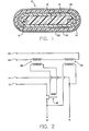
- FIG. 1 shows a heater 10.
- the heater 10 includes two elongate electrodes 12 and 14 which are connectable to a power supply (not shown).
- the heater 10 also includes a continuous strip 16 of a PTC conductive polymer that surrounds the electrodes 12 and 14.
- An insulating jacket 18 encloses this heating member, which is made up of the electrodes 12 and 14 and strip 16.
- a first electrically conductive member 20 surrounds the insulating jacket 18.
- a separating and insulating member 22 surrounds the first conductive member 20.
- a second electrically conductive member 24 surrounds the first conductive member 20 and is separated and insulated therefrom by the separating member 22.
- FIG. 2 is a schematic of an electrical circuit of the invention and shows one way of implementing the claimed method.
- the heater 10 of Figure 1 is connected so that the electrodes 12 and 14 of the unimpaired heater are connected to phase (o) and neutral (n) of a power supply, respectively.
- this power supply circuit is closed by way of an electro-mechanical switch 26. If the heater 10 becomes impaired, however, the electro-mechanical switch 26 opens, thus disconnecting the heater 10 from the power supply.
- the electro-mechanical switch 26 is part of a transformer circuit 28.
- the transformer circuit 28 is magnetically coupled to the first and second electrically conductive members 20 and 24. If the heater 10 is unimpaired, the impedance between the members 20 and 24 is very high. Therefore, the electrical loop defined by the members 20 and 24 is basically an open circuit and no current flows in the electrical loop. Accordingly, no voltage is induced in the transformer circuit 28 and the electro-mechanical switch 26 therefore stays closed. In contrast, when the heater 10 is impaired, the impedance between the first and second electrically conductive members 20 and 24 drops significantly.
- the source of the impressed voltage into the electrical loop is a second transformer circuit 30.
- the primary is connected to phase and neutral of the power supply, and the secondary comprises a portion of the electrical loop.
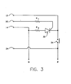
- FIG 3 shows another way of implementing the claimed method and features the employment of a silicon controlled switch circuit (SCS) 32 connected in parallel between the electrodes 12 and 14. Also shown are load resistors R 1 ,and R 2 for effective implementation of the switch circuit 32.
- the SCS circuit 32 replaces the electro-mechanical switch 26 circuit employed in the Figure 2 embodiment.
- the SCS circuit 32 in comparison to the electro-mechanical switch 26 circuit, responds in a quicker manner e.g. by a factor of 10, to changes in impedance between the first and second electrically conductive members 20 and 24.
- the Figure 3 embodiment works in the following manner.
- the SCS circuit 32 is an open circuit.
- the impedance between the conductive members 20 and 24 quickly drops. This produces a surge of current in the SCS circuit 32 which responds by switching to a short circuit. Since the SCS circuit 32 is connected in parallel with the electrodes 12 and 14, the short circuit in turn produces a surge of current through a circuit breaker 34. When this happens, the circuit breaker 34 opens and disconnects the heater 10 from the power supply.
Landscapes
- Control Of Resistance Heating (AREA)
- Resistance Heating (AREA)
- Investigating Or Analyzing Materials By The Use Of Electric Means (AREA)
- Testing Of Short-Circuits, Discontinuities, Leakage, Or Incorrect Line Connections (AREA)
- Investigating Or Analyzing Materials Using Thermal Means (AREA)
Applications Claiming Priority (2)
| Application Number | Priority Date | Filing Date | Title |
|---|---|---|---|
| US716780 | 1985-03-26 | ||
| US06/716,780 US4698583A (en) | 1985-03-26 | 1985-03-26 | Method of monitoring a heater for faults |
Publications (2)
| Publication Number | Publication Date |
|---|---|
| EP0196885A2 true EP0196885A2 (fr) | 1986-10-08 |
| EP0196885A3 EP0196885A3 (fr) | 1988-01-27 |
Family
ID=24879396
Family Applications (1)
| Application Number | Title | Priority Date | Filing Date |
|---|---|---|---|
| EP86302282A Withdrawn EP0196885A3 (fr) | 1985-03-26 | 1986-03-26 | Procédé pour contrôler un appareil de chauffage |
Country Status (4)
| Country | Link |
|---|---|
| US (1) | US4698583A (fr) |
| EP (1) | EP0196885A3 (fr) |
| JP (1) | JPS61281490A (fr) |
| CA (1) | CA1262470A (fr) |
Cited By (1)
| Publication number | Priority date | Publication date | Assignee | Title |
|---|---|---|---|---|
| EP0270370A3 (en) * | 1986-12-05 | 1990-09-26 | Raychem Corporation (A California Corporation) | Electrical heaters |
Families Citing this family (57)
| Publication number | Priority date | Publication date | Assignee | Title |
|---|---|---|---|---|
| US4833398A (en) * | 1986-10-16 | 1989-05-23 | Buchan Robert E | Electric water heater analyzer |
| EP1046206A4 (fr) * | 1997-12-10 | 2005-05-25 | Bpw Inc | Cable de detection de defauts et appareil d'alarme |
| US6288372B1 (en) * | 1999-11-03 | 2001-09-11 | Tyco Electronics Corporation | Electric cable having braidless polymeric ground plane providing fault detection |
| EA200201127A1 (ru) | 2000-04-24 | 2003-06-26 | Шелл Интернэшнл Рисерч Маатсхаппий Б.В. | Извлечение углеводородов на месте залегания из керогенсодержащей формации |
| US6877555B2 (en) | 2001-04-24 | 2005-04-12 | Shell Oil Company | In situ thermal processing of an oil shale formation while inhibiting coking |
| CN100540843C (zh) | 2001-10-24 | 2009-09-16 | 国际壳牌研究有限公司 | 利用自然分布型燃烧器对含烃岩层进行就地热处理的方法 |
| US7121341B2 (en) | 2002-10-24 | 2006-10-17 | Shell Oil Company | Conductor-in-conduit temperature limited heaters |
| US7285306B1 (en) | 2003-04-18 | 2007-10-23 | United States Of America As Represented By The Administrator Of The National Aeronautics And Space Administration | Process for self-repair of insulation material |
| CA2524689C (fr) | 2003-04-24 | 2012-05-22 | Shell Canada Limited | Procedes thermiques pour formations souterraines |
| CA2563583C (fr) | 2004-04-23 | 2013-06-18 | Shell Internationale Research Maatschappij B.V. | Modules de chauffage a temperature limitee utilises pour chauffer des formations souterraines |
| US8070840B2 (en) | 2005-04-22 | 2011-12-06 | Shell Oil Company | Treatment of gas from an in situ conversion process |
| US20080191833A1 (en) * | 2005-05-25 | 2008-08-14 | Callsmart Uk Limited | Thermal Protection For Electrical Installations and Fittings |
| KR101434259B1 (ko) | 2005-10-24 | 2014-08-27 | 쉘 인터내셔날 리써취 마트샤피지 비.브이. | 탄화수소 함유 지층을 처리하기 위한 병합 발생 시스템 및방법 |
| EP2010754A4 (fr) | 2006-04-21 | 2016-02-24 | Shell Int Research | Ajustement de compositions d'alliages pour obtenir des proprietes choisies dans des systemes de chauffage a temperature limitee |
| CN101164639B (zh) * | 2006-10-19 | 2012-04-18 | 首安工业消防有限公司 | 一种带短路故障报警的不可恢复式线型感温探测器 |
| CA2665865C (fr) | 2006-10-20 | 2015-06-16 | Shell Internationale Research Maatschappij B.V. | Chauffage de formations contenant des hydrocarbures dans une sequence etagee a demarrage en spirale |
| CN101680287B (zh) | 2007-04-20 | 2013-12-18 | 国际壳牌研究有限公司 | 用于地下地层的加热系统和用于加热地下地层的方法 |
| JP5379804B2 (ja) | 2007-10-19 | 2013-12-25 | シエル・インターナシヨネイル・リサーチ・マーチヤツピイ・ベー・ウイ | 炭化水素含有層の処理用熱源の不規則な間隔 |
| EP2262978A1 (fr) | 2008-04-18 | 2010-12-22 | Shell Internationale Research Maatschappij B.V. | Utilisation de mines et de tunnels pour le traitement de formations souterraines contenant des hydrocarbures |
| AU2009303608B2 (en) | 2008-10-13 | 2013-11-14 | Shell Internationale Research Maatschappij B.V. | Using self-regulating nuclear reactors in treating a subsurface formation |
| US8448707B2 (en) | 2009-04-10 | 2013-05-28 | Shell Oil Company | Non-conducting heater casings |
| US8816203B2 (en) | 2009-10-09 | 2014-08-26 | Shell Oil Company | Compacted coupling joint for coupling insulated conductors |
| US9466896B2 (en) * | 2009-10-09 | 2016-10-11 | Shell Oil Company | Parallelogram coupling joint for coupling insulated conductors |
| US8356935B2 (en) * | 2009-10-09 | 2013-01-22 | Shell Oil Company | Methods for assessing a temperature in a subsurface formation |
| US9127523B2 (en) | 2010-04-09 | 2015-09-08 | Shell Oil Company | Barrier methods for use in subsurface hydrocarbon formations |
| US8701769B2 (en) | 2010-04-09 | 2014-04-22 | Shell Oil Company | Methods for treating hydrocarbon formations based on geology |
| US8502120B2 (en) | 2010-04-09 | 2013-08-06 | Shell Oil Company | Insulating blocks and methods for installation in insulated conductor heaters |
| US8820406B2 (en) | 2010-04-09 | 2014-09-02 | Shell Oil Company | Electrodes for electrical current flow heating of subsurface formations with conductive material in wellbore |
| US8939207B2 (en) | 2010-04-09 | 2015-01-27 | Shell Oil Company | Insulated conductor heaters with semiconductor layers |
| US8631866B2 (en) | 2010-04-09 | 2014-01-21 | Shell Oil Company | Leak detection in circulated fluid systems for heating subsurface formations |
| US8857051B2 (en) | 2010-10-08 | 2014-10-14 | Shell Oil Company | System and method for coupling lead-in conductor to insulated conductor |
| US8586867B2 (en) | 2010-10-08 | 2013-11-19 | Shell Oil Company | End termination for three-phase insulated conductors |
| US8943686B2 (en) | 2010-10-08 | 2015-02-03 | Shell Oil Company | Compaction of electrical insulation for joining insulated conductors |
| US9016370B2 (en) | 2011-04-08 | 2015-04-28 | Shell Oil Company | Partial solution mining of hydrocarbon containing layers prior to in situ heat treatment |
| RU2587459C2 (ru) | 2011-04-08 | 2016-06-20 | Шелл Интернэшнл Рисерч Маатсхаппий Б.В. | Системы для соединения изолированных проводников |
| CN104011327B (zh) | 2011-10-07 | 2016-12-14 | 国际壳牌研究有限公司 | 利用地下地层中的绝缘导线的介电性能来确定绝缘导线的性能 |
| CA2850741A1 (fr) | 2011-10-07 | 2013-04-11 | Manuel Alberto GONZALEZ | Agencement de dilatation thermique pour systemes a ecoulement de fluide utilises pour l'echauffement de formations souterraines |
| JO3139B1 (ar) | 2011-10-07 | 2017-09-20 | Shell Int Research | تشكيل موصلات معزولة باستخدام خطوة اختزال أخيرة بعد المعالجة الحرارية. |
| JO3141B1 (ar) | 2011-10-07 | 2017-09-20 | Shell Int Research | الوصلات المتكاملة للموصلات المعزولة |
| WO2013112133A1 (fr) | 2012-01-23 | 2013-08-01 | Genie Ip B.V. | Modèle de système de chauffage destiné au traitement thermique in situ d'une formation souterraine contenant des hydrocarbures |
| US9733201B2 (en) | 2013-11-15 | 2017-08-15 | Pentair Thermal Management Llc | Thermal age tracking system and method |
| US20180063887A1 (en) * | 2016-09-01 | 2018-03-01 | Hamilton Sundstrand Corporation | Heated ptc element with protection circuit |
| US10564203B2 (en) | 2017-03-24 | 2020-02-18 | Rosemount Aerospace Inc. | Probe heater remaining useful life determination |
| US10895592B2 (en) | 2017-03-24 | 2021-01-19 | Rosemount Aerospace Inc. | Probe heater remaining useful life determination |
| US11060992B2 (en) | 2017-03-24 | 2021-07-13 | Rosemount Aerospace Inc. | Probe heater remaining useful life determination |
| US10180449B2 (en) | 2017-03-24 | 2019-01-15 | Rosemount Aerospace Inc. | Probe heater remaining useful life determination |
| US10197517B2 (en) | 2017-03-24 | 2019-02-05 | Rosemount Aerospace, Inc. | Probe heater remaining useful life determination |
| US10914777B2 (en) | 2017-03-24 | 2021-02-09 | Rosemount Aerospace Inc. | Probe heater remaining useful life determination |
| US10151785B2 (en) | 2017-03-24 | 2018-12-11 | Rosemount Aerospace Inc. | Probe heater remaining useful life determination |
| IT201700091796A1 (it) * | 2017-08-08 | 2019-02-08 | Irca Spa | Metodo e dispositivo per la misura di temperatura in resistenze elettriche di potenza |
| US11061080B2 (en) | 2018-12-14 | 2021-07-13 | Rosemount Aerospace Inc. | Real time operational leakage current measurement for probe heater PHM and prediction of remaining useful life |
| US10962580B2 (en) | 2018-12-14 | 2021-03-30 | Rosemount Aerospace Inc. | Electric arc detection for probe heater PHM and prediction of remaining useful life |
| US11639954B2 (en) | 2019-05-29 | 2023-05-02 | Rosemount Aerospace Inc. | Differential leakage current measurement for heater health monitoring |
| US11472562B2 (en) | 2019-06-14 | 2022-10-18 | Rosemount Aerospace Inc. | Health monitoring of an electrical heater of an air data probe |
| US11930563B2 (en) | 2019-09-16 | 2024-03-12 | Rosemount Aerospace Inc. | Monitoring and extending heater life through power supply polarity switching |
| US11293995B2 (en) | 2020-03-23 | 2022-04-05 | Rosemount Aerospace Inc. | Differential leakage current measurement for heater health monitoring |
| US11630140B2 (en) | 2020-04-22 | 2023-04-18 | Rosemount Aerospace Inc. | Prognostic health monitoring for heater |
Family Cites Families (13)
| Publication number | Priority date | Publication date | Assignee | Title |
|---|---|---|---|---|
| US2752590A (en) * | 1954-03-01 | 1956-06-26 | Specialties Dev Corp | Insulation failure detector for electric cables |
| US3005150A (en) * | 1960-11-15 | 1961-10-17 | Samuel H Behr | Apparatus for determining the condition of electrical insulation |
| US3277364A (en) * | 1963-02-28 | 1966-10-04 | Ernest B Abrahamson | Apparatus for testing conductivity of an unknown impedance and including silicon controlled rectifier detector means |
| US3359434A (en) * | 1965-04-06 | 1967-12-19 | Control Data Corp | Silicon controlled rectifier arrangement for improved shortcircuit protection |
| US3475594A (en) * | 1967-08-16 | 1969-10-28 | Ardco Inc | Electrically heated glass panel with anti-shock control circuit having electronic switches |
| US3761734A (en) * | 1971-09-09 | 1973-09-25 | Texas Instruments Inc | Electronic control system |
| US3861029A (en) * | 1972-09-08 | 1975-01-21 | Raychem Corp | Method of making heater cable |
| US3941975A (en) * | 1974-02-27 | 1976-03-02 | Ira W. Fine | Glass panel circuit breaker |
| US4421582A (en) * | 1975-08-04 | 1983-12-20 | Raychem Corporation | Self-heating article with deformable electrodes |
| NL7603997A (nl) * | 1976-04-15 | 1977-10-18 | Philips Nv | Elektrische verhittingsinrichting omvattende een weerstandslichaam uit p.t.c.-materiaal. |
| US4487057A (en) * | 1980-09-16 | 1984-12-11 | Raychem Corporation | Continuous sense and locate device |
| US4435639A (en) * | 1982-09-15 | 1984-03-06 | Raychem Corporation | Electrical devices with water-blocking insulation |
| JPS59118040U (ja) * | 1983-01-31 | 1984-08-09 | アルプス電気株式会社 | 入力装置 |
-
1985
- 1985-03-26 US US06/716,780 patent/US4698583A/en not_active Expired - Lifetime
-
1986
- 1986-03-25 CA CA000505014A patent/CA1262470A/fr not_active Expired
- 1986-03-26 EP EP86302282A patent/EP0196885A3/fr not_active Withdrawn
- 1986-03-26 JP JP61069702A patent/JPS61281490A/ja active Pending
Cited By (1)
| Publication number | Priority date | Publication date | Assignee | Title |
|---|---|---|---|---|
| EP0270370A3 (en) * | 1986-12-05 | 1990-09-26 | Raychem Corporation (A California Corporation) | Electrical heaters |
Also Published As
| Publication number | Publication date |
|---|---|
| US4698583A (en) | 1987-10-06 |
| CA1262470A (fr) | 1989-10-24 |
| JPS61281490A (ja) | 1986-12-11 |
| EP0196885A3 (fr) | 1988-01-27 |
Similar Documents
| Publication | Publication Date | Title |
|---|---|---|
| EP0196885A2 (fr) | Procédé pour contrôler un appareil de chauffage | |
| US4785163A (en) | Method for monitoring a heater | |
| US4822983A (en) | Electrical heaters | |
| US4583146A (en) | Fault current interrupter | |
| US4967176A (en) | Assemblies of PTC circuit protection devices | |
| EP0121990B1 (fr) | Systèmes de contrôle électriques | |
| CA1041598A (fr) | Limiteur de courant pour systemes de transmission electrique a grande puissance | |
| US5002501A (en) | Electrical plug | |
| CN105098748A (zh) | 一种浪涌保护器及提升其暂时过电压耐受能力的方法 | |
| EP0966748A1 (fr) | Coupe-circuit a fonction d'interruption d'arc amelioree | |
| US5969928A (en) | Shunt for circuit protection device | |
| US4645912A (en) | Pipeline heated by a diagonal feeding, band-form, electrical heat-generating apparatus | |
| US4031356A (en) | Heat panel safety system | |
| CA1128153A (fr) | Systeme protecteur pour condensateur | |
| NZ197765A (en) | Electric blanket safety circuit | |
| US4439801A (en) | Electrical load imbalance detection and protection apparatus | |
| JPS6439230A (en) | Protective device for superconducting circuit | |
| DE3902400A1 (de) | Elektrischer warmwasserbereiter | |
| GB2186134A (en) | Heating circuits with protective arrangements | |
| Sun et al. | The voltage dependence of switching in a polymer current limiter device | |
| CA1138025A (fr) | Systeme de protection contre les fuites a la terre avec pouvoir de coupure reduit | |
| EP0668646A2 (fr) | Perfectionnements relatifs aux panneaux chauffants électriques | |
| Duggal | An upper limit for high power switching with a polymer current limiter device | |
| KR950004454Y1 (ko) | 전기기기의 소손 방지 장치 | |
| Wroe | High temperature superconductors for fault current limitation on local power distribution networks |
Legal Events
| Date | Code | Title | Description |
|---|---|---|---|
| PUAI | Public reference made under article 153(3) epc to a published international application that has entered the european phase |
Free format text: ORIGINAL CODE: 0009012 |
|
| 17P | Request for examination filed |
Effective date: 19860404 |
|
| AK | Designated contracting states |
Kind code of ref document: A2 Designated state(s): AT BE CH DE FR GB IT LI NL SE |
|
| PUAL | Search report despatched |
Free format text: ORIGINAL CODE: 0009013 |
|
| AK | Designated contracting states |
Kind code of ref document: A3 Designated state(s): AT BE CH DE FR GB IT LI NL SE |
|
| RAP1 | Party data changed (applicant data changed or rights of an application transferred) |
Owner name: RAYCHEM CORPORATION (A DELAWARE CORPORATION) |
|
| 17Q | First examination report despatched |
Effective date: 19900927 |
|
| STAA | Information on the status of an ep patent application or granted ep patent |
Free format text: STATUS: THE APPLICATION IS DEEMED TO BE WITHDRAWN |
|
| 18D | Application deemed to be withdrawn |
Effective date: 19910409 |
|
| RIN1 | Information on inventor provided before grant (corrected) |
Inventor name: SANDBERG, CHESTER L. |