EP0197015B1 - Schwimmend gelagerter, zylindrischer Dorn und Verfahren zur Herstellung von Rohren - Google Patents
Schwimmend gelagerter, zylindrischer Dorn und Verfahren zur Herstellung von Rohren Download PDFInfo
- Publication number
- EP0197015B1 EP0197015B1 EP86850079A EP86850079A EP0197015B1 EP 0197015 B1 EP0197015 B1 EP 0197015B1 EP 86850079 A EP86850079 A EP 86850079A EP 86850079 A EP86850079 A EP 86850079A EP 0197015 B1 EP0197015 B1 EP 0197015B1
- Authority
- EP
- European Patent Office
- Prior art keywords
- mandrel
- workpiece
- jaws
- crosshead
- friction surfaces
- Prior art date
- Legal status (The legal status is an assumption and is not a legal conclusion. Google has not performed a legal analysis and makes no representation as to the accuracy of the status listed.)
- Expired
Links
- 238000004519 manufacturing process Methods 0.000 title description 9
- 238000000034 method Methods 0.000 claims description 9
- 230000000452 restraining effect Effects 0.000 claims description 5
- 229910052751 metal Inorganic materials 0.000 claims description 4
- 239000002184 metal Substances 0.000 claims description 4
- 238000005219 brazing Methods 0.000 claims description 3
- 230000013011 mating Effects 0.000 claims description 2
- 229910001093 Zr alloy Inorganic materials 0.000 description 7
- RTAQQCXQSZGOHL-UHFFFAOYSA-N Titanium Chemical compound [Ti] RTAQQCXQSZGOHL-UHFFFAOYSA-N 0.000 description 5
- 239000010936 titanium Substances 0.000 description 5
- 239000000463 material Substances 0.000 description 4
- 229910001092 metal group alloy Inorganic materials 0.000 description 4
- 229910001069 Ti alloy Inorganic materials 0.000 description 3
- 229910045601 alloy Inorganic materials 0.000 description 3
- 239000000956 alloy Substances 0.000 description 3
- QCWXUUIWCKQGHC-UHFFFAOYSA-N Zirconium Chemical compound [Zr] QCWXUUIWCKQGHC-UHFFFAOYSA-N 0.000 description 2
- 230000015572 biosynthetic process Effects 0.000 description 2
- -1 most preferably Inorganic materials 0.000 description 2
- 229910052719 titanium Inorganic materials 0.000 description 2
- 229910052726 zirconium Inorganic materials 0.000 description 2
- 229910000906 Bronze Inorganic materials 0.000 description 1
- FYYHWMGAXLPEAU-UHFFFAOYSA-N Magnesium Chemical compound [Mg] FYYHWMGAXLPEAU-UHFFFAOYSA-N 0.000 description 1
- ZOKXTWBITQBERF-UHFFFAOYSA-N Molybdenum Chemical compound [Mo] ZOKXTWBITQBERF-UHFFFAOYSA-N 0.000 description 1
- 229910052782 aluminium Inorganic materials 0.000 description 1
- XAGFODPZIPBFFR-UHFFFAOYSA-N aluminium Chemical compound [Al] XAGFODPZIPBFFR-UHFFFAOYSA-N 0.000 description 1
- 238000013459 approach Methods 0.000 description 1
- 239000010974 bronze Substances 0.000 description 1
- 238000010276 construction Methods 0.000 description 1
- KUNSUQLRTQLHQQ-UHFFFAOYSA-N copper tin Chemical compound [Cu].[Sn] KUNSUQLRTQLHQQ-UHFFFAOYSA-N 0.000 description 1
- 230000000694 effects Effects 0.000 description 1
- 150000004678 hydrides Chemical class 0.000 description 1
- 239000011777 magnesium Substances 0.000 description 1
- 229910052749 magnesium Inorganic materials 0.000 description 1
- 150000002739 metals Chemical class 0.000 description 1
- 238000005555 metalworking Methods 0.000 description 1
- 229910052750 molybdenum Inorganic materials 0.000 description 1
- 239000011733 molybdenum Substances 0.000 description 1
- 229910052758 niobium Inorganic materials 0.000 description 1
- 239000010955 niobium Substances 0.000 description 1
- 230000002093 peripheral effect Effects 0.000 description 1
- 238000005096 rolling process Methods 0.000 description 1
- WFKWXMTUELFFGS-UHFFFAOYSA-N tungsten Chemical compound [W] WFKWXMTUELFFGS-UHFFFAOYSA-N 0.000 description 1
- 229910052721 tungsten Inorganic materials 0.000 description 1
- 239000010937 tungsten Substances 0.000 description 1
Images


Classifications
-
- B—PERFORMING OPERATIONS; TRANSPORTING
- B21—MECHANICAL METAL-WORKING WITHOUT ESSENTIALLY REMOVING MATERIAL; PUNCHING METAL
- B21B—ROLLING OF METAL
- B21B21/00—Pilgrim-step tube-rolling, i.e. pilger mills
-
- B—PERFORMING OPERATIONS; TRANSPORTING
- B21—MECHANICAL METAL-WORKING WITHOUT ESSENTIALLY REMOVING MATERIAL; PUNCHING METAL
- B21B—ROLLING OF METAL
- B21B25/00—Mandrels for metal tube rolling mills, e.g. mandrels of the types used in the methods covered by group B21B17/00; Accessories or auxiliary means therefor ; Construction of, or alloys for, mandrels or plugs
- B21B25/02—Guides, supports, or abutments for mandrels, e.g. carriages or steadiers; Adjusting devices for mandrels
-
- Y—GENERAL TAGGING OF NEW TECHNOLOGICAL DEVELOPMENTS; GENERAL TAGGING OF CROSS-SECTIONAL TECHNOLOGIES SPANNING OVER SEVERAL SECTIONS OF THE IPC; TECHNICAL SUBJECTS COVERED BY FORMER USPC CROSS-REFERENCE ART COLLECTIONS [XRACs] AND DIGESTS
- Y10—TECHNICAL SUBJECTS COVERED BY FORMER USPC
- Y10T—TECHNICAL SUBJECTS COVERED BY FORMER US CLASSIFICATION
- Y10T279/00—Chucks or sockets
- Y10T279/17—Socket type
- Y10T279/17957—Friction grip
-
- Y—GENERAL TAGGING OF NEW TECHNOLOGICAL DEVELOPMENTS; GENERAL TAGGING OF CROSS-SECTIONAL TECHNOLOGIES SPANNING OVER SEVERAL SECTIONS OF THE IPC; TECHNICAL SUBJECTS COVERED BY FORMER USPC CROSS-REFERENCE ART COLLECTIONS [XRACs] AND DIGESTS
- Y10—TECHNICAL SUBJECTS COVERED BY FORMER USPC
- Y10T—TECHNICAL SUBJECTS COVERED BY FORMER US CLASSIFICATION
- Y10T279/00—Chucks or sockets
- Y10T279/34—Accessory or component
- Y10T279/3462—Jaw insert
Definitions
- This invention relates to producing tubes from hollow workpieces, and more in particular to a method and apparatus for producing tubes from mills which have features of prior art mills known as a McKay rocker mill or a FHR reciprocating cross- head type rocker mill.
- the mill used in practicing the present invention also has features disclosed in U.S. Patent No. 3,487,675, which is regarded as closest prior art document.
- U.S. Patent No. 4,090,386 relates to a method of producing zircaloy tubes of small internal diameter where it is desirable to have high rates of reduction in the wall thickness.
- the disclosure is directed to zircaloy tubes having close tolerances in inside and outside diameters and from the standpoint of ovality.
- the rocker mechanism produces tubes with a fine grain structure, improved hydride orientation and higher ratios of strength to ductility.
- the rocker mechanism permits the workpiece to be turned around its axis a predetermined number of degrees for each time that the workpiece is advanced one step into the forming zone.
- the mandrel, employed in the production of the tubing is securely locked within the cross-head of the device.
- U.S. Patent No. 4,233,834 is directed to a method and apparatus for producing zircaloy tubes and the tubing produced by the apparatus in which the spiral formation of the wall-thickness eccentricity is controlled. This is done by controlling the angle at which the metal working forces are exerted so as to minimize the turning moment or torque effect which results in producing the spiral formation of the tubing.
- An object of the present invention is to provide improved methods for producing high-quality metal alloy tubes.
- a further object is to provide for the above in a manner to permit a reduction in the time required to form finished tubes from tubes of greater wall thickness than the finished tubes.
- a further object is to provide for the above in a manner which overcomes difficulties encountered in the past and which permits high rates of reduction of wall thickness in forming such tubes. This difficulty is encountered when working with metals which do not lubricate well together.
- the present invention is particularly directed toward producing metal alloy, most preferably, titanium or zirconium alloy, tubes of small internal diameter from cylindrical workpieces where it is desirable to have high rates of reduction in the wall thickness. It has been found that the invention permits high output rate with increased reduction rates and with less tool cost as represented by avoidance of breakage of mandrels.
- metal alloy tubes such as, for example, titanium or zirconium alloy tubes
- cylindrical mandrels may encounter failure by tensile fracture or reduction in diameter during rocking when manufacturing tubes of small O.D., i.e., on the order of 0.250".
- stress in the mandrel is a combination of compressive stresses in the rolling operation and tensile stresses set up in the mandrel, which is restrained at one end, and held by friction of the reduction cone at the other.
- the present invention obviates and/or reduces the problems by the characterizing features of claims 1 and 6 in connection with their pre-characterizing parts, that means by utilizing a longer mandrel which is restrained at the rocker crosshead by friction instead of a positive locking force.
- This arrangement permits the mandrel to slide in the cross- head, upon the application of the proper friction force. Accordingly, the high tensile forces which would otherwise cause mandrel failure are not produced and mandrel life is significantly increased.
- Other cost savings in equipment downtime, labor time for replacement of mandrels, etc. are also realized.
- a McKay type rocker mill 2 is represented schematically with a stationary base 4, a movable chuck or crosshead 6 in which is securely locked a cylindrical mandrel 17.
- the jaws 19 and 20 lock the mandrel in a fixed position, relative to the jaws, by engagement with cut-out sections, one of which is indicated at 19', provided in the mandrel 17.
- the mandrel is positioned within the workpiece and has a uniform external diameter which is only slightly less than the internal diameter of the workpiece 18.
- the left-hand end of the workpiece is shown in a forming zone 10 during the forming operation which is being performed by a pair of forming rolls 11 and 12 rotatably mounted in a movable rollstand 9.
- Stand 9 is oscillated by a crank arm assembly 7 with the movement being such that the forming zone 10 is moved axially with respect to the workpiece.
- the workpiece is advanced step-by-step into and through the forming zone by a screw thread assembly having a threaded shaft 22 extending through the supporting bracket 26 for the chuck or crosshead 6.
- rolls 11 and 12 are mounted upon shafts 13 and 14, respectively, and each of them has a groove (see Fig. 3) comprising a primary forming portion 30, a finishing portion 31, and a dwell portion 32.
- the surfaces of portions 30 and 31 of each of the grooves has a generally semicircular cross-section the axis of which is concentric with the axis of the mandrel and the workpiece when the respective portions of the groove mate at the forming zone as shown in Fig. 4.
- each of the grooves is widened at its edges to provide a relief area 15.
- the peripheral edges 35 of the rolls mate along a line between the axis of the rolls which intersect the axis of the workpiece.
- the arc of the dwell portion 32 relative to the roll axis is usually on the order of 60-120 ° .
- the primary forming portion 30 is usually longer than the finishing portion 31, and the dwell portion extends the remainder of the circumference of the roll.
- the rollstand oscillates to the right and left from the position shown in Fig. 1, and is, in fact, moving to the left in a primary tube-forming movement of stroke.
- portions 30 of the grooves are engaging the workpiece, with roll 11 turning counterclockwise and roll 12 turning clockwise.
- the movement of the roll stand carrying the rolls relative to the rotation of the rolls is such that the finishing portions 31 of the grooves mate at their ends adjacent the dwell portions 32 when the rollstand and rolls are in the extreme left-hand position.
- the movements are then reversed simultaneously so that the rolls start to turn in their respective opposite directions at the same time that the rollstand starts to move the rolls to the right.
- Most of the reduction is normally taken on the forward stroke from the right to the left.
- a certain amount of the deformation work can be taken during the return stroke from the left to the right.
- the respective drives to produce the movements of the workpiece and the forming rolls are known in the art.
- the general construction of the forming rolls is also known in the art, for example, in U.S. Patent No. 3,487,675 in which forming rolls are supported on a stationary stand and the workpiece and a cylindrical mandrel are oscillated axially within the tube-forming zone.
- the prior tube-forming mills of the McKay rocker type have stationary mandrels which are tapered. Such mills have certain drawbacks in use for producing tubes of metal alloys such as titanium or zirconium alloys, but they have been used commercially for that purpose.
- the present invention utilizes certain of the tube-forming principles of the McKay rocker mill and the FHR mik referred to above.
- the cylindrical surface of the mandrel against which the inner surface of the workpiece is compressed provides radial forces in opposition to the forces produced by the rolls against the outer surface of the workpiece.
- a cylindrical mandrel must be used.
- the mandrel In a pilger mill of the McKay type, the mandrel is stationary due to the previously discussed locking arrangement. Rocking on a stationary cylindrical mandrel results in high compressive radial stresses and high axial tensile stresses in the mandrel, especially if the reduction is high. If the cylindrical mandrel is fed forward, from the right to the left in Fig.
- the compressive radial forces in the mandrel will be slightly lower.
- the axial tensile stresses will be substantially less and the number of loading cycles on any one zone of the mandrel during the rocking of a tube will be less compared with the conditions when using a stationary mandrel.
- the decrease of the tensile stresses is especially important as the life length of the mandrels is on that part of the S-N fatigue curve where very small changes in stress can lead to a significant change in the mandrel life.
- the mandrel 17 is of a uniform size from end to end.
- the movable chuck 6 is provided with a friction device indicated generally at 16 for engagement with the mandrel 17.
- the movable chuck 6 is a multijaw lathe chuck.
- Two jaws, indicated at 19 and 20, are shown. However, it should be understood that more than two such jaws may be used, if necessary.
- the jaws, along their radially inwardly directed surfaces, are provided with friction surfaces 21 and 23.
- the opening and closing of the jaws may be controlled by the use of a torque wrench (not-shown) so as to engage the mandrel 17 with a predetermined frictional force as set by the torque wrench.
- the material of the friction surfaces 21 and 23 is bronze.
- the friction surfaces 21 and 23 may be attached to the jaws 19 and 20 by frictional engagement therewith. This may be accomplished by. utilizing friction surfaces of greater length than the jaws 21 and 23.
- the friction surfaces may then be fitted to the jaws with end sections of the friction surfaces extending axially beyond the jaws. The end sections would be bent in a radially outward direction parallel to the radially inwardly directed jaws 19 and 20. A tight friction fitting between the jaws and the end sections would hold the friction surfaces in place with respect to the jaws 19 and 20.
- the friction surfaces could be fitted to the jaws 19 and 20 by brazing.
- the mandrel 17 is gripped by the friction contact surfaces 21 and 23 when the jaws are moved into position, by use of the torque wrench, for engagement with the mandrel.
- the mandrel 17 is provided as a straight rod with parallel sides. This permits frictional engagement and ensures that no locking engagement of the jaws, with the mandrel, occurs.
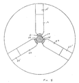
- chuck jaws are shown at 19, 20 and 27.
- Friction surfaces are indicated at 21, 23 and 25.
- the friction surfaces are attached to the jaws in the above-described manner.
- the chuck jaws 19, 20 and 27 are movable in jaw grooves 19', 20' and 27'.
- the mandrel is indicated at reference numeral 17.
- the jaws are brought into contact with the mandrel by a torque wrench actuating a chuck jaw movement mechanism (not shown).
- the chuck jaws and their associated friction surfaces grip the mandrel 17 with a predetermined force.
- the total restraining friction force of the crosshead, on the mandrel is less than the yield strength of the mandrel. Of course, such a mandrel yield strength can be predetermined. However, the total restraining friction force would be enough to restrain the mandrel from being pulled through the rocker by the movable roll stand 9.
- 47.46 Nm (35 ft.-lbs.) may be applied to the chuck jaw movement mechanism so as to securely grip mandrel 17 by friction surfaces 21, 23 and ' 25.
- the present invention may be utilized in the production of tubing of the above-described type utilizing refractory (e.g.) tantalium, tungsten and molybdenum or reactive (e.g.) aluminum, magnesium, titanium, zirconium and niobium metals or their alloys. Zirconium and titanium and their alloys are the preferred materials for use in the present invention.
- refractory e.g.
- tantalium tungsten and molybdenum
- reactive (e.g.) aluminum, magnesium, titanium, zirconium and niobium metals or their alloys e.g.
- Zirconium and titanium and their alloys are the preferred materials for use in the present invention.
Landscapes
- Engineering & Computer Science (AREA)
- Mechanical Engineering (AREA)
- Forging (AREA)
- Lining Or Joining Of Plastics Or The Like (AREA)
Claims (11)
Applications Claiming Priority (2)
| Application Number | Priority Date | Filing Date | Title |
|---|---|---|---|
| US714800 | 1985-03-22 | ||
| US06/714,800 US4655068A (en) | 1985-03-22 | 1985-03-22 | Floating cylindrical mandrel and method for producing tubing |
Publications (2)
| Publication Number | Publication Date |
|---|---|
| EP0197015A1 EP0197015A1 (de) | 1986-10-08 |
| EP0197015B1 true EP0197015B1 (de) | 1989-07-26 |
Family
ID=24871512
Family Applications (1)
| Application Number | Title | Priority Date | Filing Date |
|---|---|---|---|
| EP86850079A Expired EP0197015B1 (de) | 1985-03-22 | 1986-03-04 | Schwimmend gelagerter, zylindrischer Dorn und Verfahren zur Herstellung von Rohren |
Country Status (5)
| Country | Link |
|---|---|
| US (1) | US4655068A (de) |
| EP (1) | EP0197015B1 (de) |
| JP (1) | JPS61269910A (de) |
| KR (1) | KR900000727B1 (de) |
| DE (1) | DE3664573D1 (de) |
Families Citing this family (6)
| Publication number | Priority date | Publication date | Assignee | Title |
|---|---|---|---|---|
| US4930328A (en) * | 1989-01-17 | 1990-06-05 | Sandvik Special Metals Corp. | Method and apparatus for reloading a pilgering mill |
| JP2010240681A (ja) * | 2009-04-03 | 2010-10-28 | Sumitomo Metal Ind Ltd | 冷間圧延法による超薄肉継目無金属管の製造方法 |
| WO2010122581A2 (en) * | 2009-04-24 | 2010-10-28 | Arihantdomestic Appliances Limited | A low carbon welded tube and process of manufacture thereof |
| DE102009003175A1 (de) * | 2009-05-15 | 2010-11-18 | Sandvik Materials Technology Deutschland Gmbh | Vorschubantrieb für eine Kaltpilgerwalzanlage |
| KR101584300B1 (ko) | 2015-06-11 | 2016-01-11 | 최광준 | 맨드릴용 윤활유 공급이 가능한 필거 밀 |
| CN120306417A (zh) * | 2025-06-17 | 2025-07-15 | 常州市淮建机械设备制造有限公司 | 一种全自动冷轧管机 |
Citations (3)
| Publication number | Priority date | Publication date | Assignee | Title |
|---|---|---|---|---|
| US3487675A (en) * | 1966-02-01 | 1970-01-06 | Sandvikens Jernverks Ab | Tube forming |
| US4090386A (en) * | 1977-03-21 | 1978-05-23 | Sandvik Special Metals Corporation | Method of producing zircaloy tubes |
| US4233834A (en) * | 1979-01-26 | 1980-11-18 | Sandvik Special Metal Corporation | Method and apparatus for producing zircaloy tubes and zircaloy tubes thus produced |
Family Cites Families (7)
| Publication number | Priority date | Publication date | Assignee | Title |
|---|---|---|---|---|
| NL121121C (de) * | 1957-04-30 | Esfom | ||
| US3570294A (en) * | 1967-12-06 | 1971-03-16 | Jintaro Shibata | Pipe rolling equipment |
| DE2725276C3 (de) * | 1977-06-01 | 1980-11-20 | Mannesmann Ag, 4000 Duesseldorf | Kaltpilgerwalzwerk |
| IT1086314B (it) * | 1977-09-19 | 1985-05-28 | Innocenti Santeustacchio Spa | Gabbia di sostegno e guida del mandrino in laminatoi continui a mandrino trattenuto |
| IT1088362B (it) * | 1977-11-07 | 1985-06-10 | Innocenti Santeustacchio Spa | Dispositivo per la guida della stanga portapunta di una macchina perforatrice di lingotti a caldo |
| US4184352A (en) * | 1978-06-08 | 1980-01-22 | Moskovsky Institut Stali I Splavov | Method for pilger rolling of tubes and mill for effecting same |
| US4277073A (en) * | 1979-10-09 | 1981-07-07 | Halliburton Company | Insert type soft chuck jaws |
-
1985
- 1985-03-22 US US06/714,800 patent/US4655068A/en not_active Expired - Lifetime
-
1986
- 1986-03-04 EP EP86850079A patent/EP0197015B1/de not_active Expired
- 1986-03-04 DE DE8686850079T patent/DE3664573D1/de not_active Expired
- 1986-03-19 KR KR1019860002044A patent/KR900000727B1/ko not_active Expired
- 1986-03-22 JP JP61062029A patent/JPS61269910A/ja active Pending
Patent Citations (3)
| Publication number | Priority date | Publication date | Assignee | Title |
|---|---|---|---|---|
| US3487675A (en) * | 1966-02-01 | 1970-01-06 | Sandvikens Jernverks Ab | Tube forming |
| US4090386A (en) * | 1977-03-21 | 1978-05-23 | Sandvik Special Metals Corporation | Method of producing zircaloy tubes |
| US4233834A (en) * | 1979-01-26 | 1980-11-18 | Sandvik Special Metal Corporation | Method and apparatus for producing zircaloy tubes and zircaloy tubes thus produced |
Also Published As
| Publication number | Publication date |
|---|---|
| KR900000727B1 (ko) | 1990-02-10 |
| US4655068A (en) | 1987-04-07 |
| JPS61269910A (ja) | 1986-11-29 |
| KR860007037A (ko) | 1986-10-06 |
| EP0197015A1 (de) | 1986-10-08 |
| DE3664573D1 (en) | 1989-08-31 |
Similar Documents
| Publication | Publication Date | Title |
|---|---|---|
| CA1075506A (en) | Method of producing zircaloy tubes | |
| US4233834A (en) | Method and apparatus for producing zircaloy tubes and zircaloy tubes thus produced | |
| US4649728A (en) | Integral joint forming of work-hardenable high alloy tubing | |
| CA1172878A (en) | Method and tool for the cold forging of internally profiled tubes | |
| US3487675A (en) | Tube forming | |
| US4655068A (en) | Floating cylindrical mandrel and method for producing tubing | |
| US4470281A (en) | Method of forming end face wall having concentric recess in tubular workpiece | |
| US4184352A (en) | Method for pilger rolling of tubes and mill for effecting same | |
| JPS60187407A (ja) | 傾斜圧延機 | |
| JPS6227281Y2 (de) | ||
| US6792781B1 (en) | Arrangement for inclined rolling of tube-shaped or bar shaped rolling products | |
| RU2104114C1 (ru) | Устройство для раздачи полых изделий | |
| US4157025A (en) | Method and mill for rolling metal billets | |
| US6205833B1 (en) | Cold pilger rolling tool for producing internally ribbed tubes | |
| JP2003136131A (ja) | 一端側に中実部を備える中空部材の製造方法 | |
| JP3369320B2 (ja) | 傾斜圧延装置 | |
| US3918284A (en) | Seamless tube mill piercer mandrel and assembly | |
| US4406142A (en) | Annular corrugator | |
| US4567744A (en) | Method and apparatus for forming long cylindrical metal products | |
| EP3068554B1 (de) | Kaltpilgerwalzwerk und verfahren zur bildung einer hohlen verkleidung innerhalb einer röhre | |
| US3357223A (en) | Tube reducing machine | |
| EP0407369B1 (de) | Walzgerüst mit leicht wechselbaren Walzgesenken | |
| US20080164695A1 (en) | Ferrules Manufactured From Hollow Stock | |
| RU2054980C1 (ru) | Способ холодной периодической прокатки труб | |
| GB1593318A (en) | Manufacture of roled products |
Legal Events
| Date | Code | Title | Description |
|---|---|---|---|
| PUAI | Public reference made under article 153(3) epc to a published international application that has entered the european phase |
Free format text: ORIGINAL CODE: 0009012 |
|
| 17P | Request for examination filed |
Effective date: 19860521 |
|
| AK | Designated contracting states |
Kind code of ref document: A1 Designated state(s): DE FR GB IT SE |
|
| 17Q | First examination report despatched |
Effective date: 19880429 |
|
| GRAA | (expected) grant |
Free format text: ORIGINAL CODE: 0009210 |
|
| AK | Designated contracting states |
Kind code of ref document: B1 Designated state(s): DE FR GB IT SE |
|
| ITF | It: translation for a ep patent filed | ||
| REF | Corresponds to: |
Ref document number: 3664573 Country of ref document: DE Date of ref document: 19890831 |
|
| ET | Fr: translation filed | ||
| PLBE | No opposition filed within time limit |
Free format text: ORIGINAL CODE: 0009261 |
|
| STAA | Information on the status of an ep patent application or granted ep patent |
Free format text: STATUS: NO OPPOSITION FILED WITHIN TIME LIMIT |
|
| 26N | No opposition filed | ||
| ITTA | It: last paid annual fee | ||
| EAL | Se: european patent in force in sweden |
Ref document number: 86850079.4 |
|
| REG | Reference to a national code |
Ref country code: GB Ref legal event code: IF02 |
|
| PGFP | Annual fee paid to national office [announced via postgrant information from national office to epo] |
Ref country code: DE Payment date: 20050224 Year of fee payment: 20 |
|
| PGFP | Annual fee paid to national office [announced via postgrant information from national office to epo] |
Ref country code: GB Payment date: 20050302 Year of fee payment: 20 |
|
| PGFP | Annual fee paid to national office [announced via postgrant information from national office to epo] |
Ref country code: SE Payment date: 20050304 Year of fee payment: 20 |
|
| PGFP | Annual fee paid to national office [announced via postgrant information from national office to epo] |
Ref country code: FR Payment date: 20050308 Year of fee payment: 20 |
|
| PGFP | Annual fee paid to national office [announced via postgrant information from national office to epo] |
Ref country code: IT Payment date: 20050330 Year of fee payment: 20 |
|
| PG25 | Lapsed in a contracting state [announced via postgrant information from national office to epo] |
Ref country code: GB Free format text: LAPSE BECAUSE OF EXPIRATION OF PROTECTION Effective date: 20060303 |
|
| REG | Reference to a national code |
Ref country code: GB Ref legal event code: PE20 |
|
| EUG | Se: european patent has lapsed |