EP0197178A1 - Verfahren zum Herstellen von Kolben aus spröden Hartstoffen - Google Patents
Verfahren zum Herstellen von Kolben aus spröden Hartstoffen Download PDFInfo
- Publication number
- EP0197178A1 EP0197178A1 EP85104328A EP85104328A EP0197178A1 EP 0197178 A1 EP0197178 A1 EP 0197178A1 EP 85104328 A EP85104328 A EP 85104328A EP 85104328 A EP85104328 A EP 85104328A EP 0197178 A1 EP0197178 A1 EP 0197178A1
- Authority
- EP
- European Patent Office
- Prior art keywords
- piston
- adhesive
- cone
- blind hole
- connecting element
- Prior art date
- Legal status (The legal status is an assumption and is not a legal conclusion. Google has not performed a legal analysis and makes no representation as to the accuracy of the status listed.)
- Granted
Links
- 238000004519 manufacturing process Methods 0.000 title claims abstract description 7
- 239000000463 material Substances 0.000 title claims abstract description 7
- 229910052574 oxide ceramic Inorganic materials 0.000 claims abstract description 14
- 239000011224 oxide ceramic Substances 0.000 claims abstract description 14
- 238000000034 method Methods 0.000 claims abstract description 9
- 238000005245 sintering Methods 0.000 claims abstract description 4
- 239000000853 adhesive Substances 0.000 claims description 28
- 230000001070 adhesive effect Effects 0.000 claims description 28
- 239000000919 ceramic Substances 0.000 claims description 22
- TWNQGVIAIRXVLR-UHFFFAOYSA-N oxo(oxoalumanyloxy)alumane Chemical compound O=[Al]O[Al]=O TWNQGVIAIRXVLR-UHFFFAOYSA-N 0.000 claims description 7
- 238000003754 machining Methods 0.000 claims description 4
- 238000003780 insertion Methods 0.000 claims description 3
- 230000037431 insertion Effects 0.000 claims description 3
- 238000013459 approach Methods 0.000 claims description 2
- 239000003822 epoxy resin Substances 0.000 claims description 2
- 229920000647 polyepoxide Polymers 0.000 claims description 2
- 239000007767 bonding agent Substances 0.000 abstract 2
- 229910052751 metal Inorganic materials 0.000 description 9
- 239000002184 metal Substances 0.000 description 9
- 239000000395 magnesium oxide Substances 0.000 description 3
- CPLXHLVBOLITMK-UHFFFAOYSA-N magnesium oxide Inorganic materials [Mg]=O CPLXHLVBOLITMK-UHFFFAOYSA-N 0.000 description 3
- AXZKOIWUVFPNLO-UHFFFAOYSA-N magnesium;oxygen(2-) Chemical compound [O-2].[Mg+2] AXZKOIWUVFPNLO-UHFFFAOYSA-N 0.000 description 3
- RVTZCBVAJQQJTK-UHFFFAOYSA-N oxygen(2-);zirconium(4+) Chemical compound [O-2].[O-2].[Zr+4] RVTZCBVAJQQJTK-UHFFFAOYSA-N 0.000 description 3
- 239000000126 substance Substances 0.000 description 3
- 229910001928 zirconium oxide Inorganic materials 0.000 description 3
- VYPSYNLAJGMNEJ-UHFFFAOYSA-N Silicium dioxide Chemical compound O=[Si]=O VYPSYNLAJGMNEJ-UHFFFAOYSA-N 0.000 description 2
- 239000004568 cement Substances 0.000 description 2
- 238000013461 design Methods 0.000 description 2
- 229910052814 silicon oxide Inorganic materials 0.000 description 2
- FRWYFWZENXDZMU-UHFFFAOYSA-N 2-iodoquinoline Chemical compound C1=CC=CC2=NC(I)=CC=C21 FRWYFWZENXDZMU-UHFFFAOYSA-N 0.000 description 1
- 240000005702 Galium aparine Species 0.000 description 1
- GWEVSGVZZGPLCZ-UHFFFAOYSA-N Titan oxide Chemical compound O=[Ti]=O GWEVSGVZZGPLCZ-UHFFFAOYSA-N 0.000 description 1
- LTPBRCUWZOMYOC-UHFFFAOYSA-N beryllium oxide Inorganic materials O=[Be] LTPBRCUWZOMYOC-UHFFFAOYSA-N 0.000 description 1
- 230000005540 biological transmission Effects 0.000 description 1
- BRPQOXSCLDDYGP-UHFFFAOYSA-N calcium oxide Chemical compound [O-2].[Ca+2] BRPQOXSCLDDYGP-UHFFFAOYSA-N 0.000 description 1
- 239000000292 calcium oxide Substances 0.000 description 1
- ODINCKMPIJJUCX-UHFFFAOYSA-N calcium oxide Inorganic materials [Ca]=O ODINCKMPIJJUCX-UHFFFAOYSA-N 0.000 description 1
- 230000001427 coherent effect Effects 0.000 description 1
- 238000011109 contamination Methods 0.000 description 1
- 229910003460 diamond Inorganic materials 0.000 description 1
- 239000010432 diamond Substances 0.000 description 1
- 238000009826 distribution Methods 0.000 description 1
- 239000002360 explosive Substances 0.000 description 1
- 230000004907 flux Effects 0.000 description 1
- 239000003966 growth inhibitor Substances 0.000 description 1
- 238000010438 heat treatment Methods 0.000 description 1
- 239000012535 impurity Substances 0.000 description 1
- 230000007774 longterm Effects 0.000 description 1
- 150000002739 metals Chemical class 0.000 description 1
- 239000000203 mixture Substances 0.000 description 1
- 239000004033 plastic Substances 0.000 description 1
- 238000012805 post-processing Methods 0.000 description 1
- 238000012545 processing Methods 0.000 description 1
- 238000003892 spreading Methods 0.000 description 1
- 239000003381 stabilizer Substances 0.000 description 1
- OGIDPMRJRNCKJF-UHFFFAOYSA-N titanium oxide Inorganic materials [Ti]=O OGIDPMRJRNCKJF-UHFFFAOYSA-N 0.000 description 1
Images


Classifications
-
- F—MECHANICAL ENGINEERING; LIGHTING; HEATING; WEAPONS; BLASTING
- F16—ENGINEERING ELEMENTS AND UNITS; GENERAL MEASURES FOR PRODUCING AND MAINTAINING EFFECTIVE FUNCTIONING OF MACHINES OR INSTALLATIONS; THERMAL INSULATION IN GENERAL
- F16J—PISTONS; CYLINDERS; SEALINGS
- F16J1/00—Pistons; Trunk pistons; Plungers
- F16J1/10—Connection to driving members
- F16J1/12—Connection to driving members with piston-rods, e.g. rigid connections
-
- F—MECHANICAL ENGINEERING; LIGHTING; HEATING; WEAPONS; BLASTING
- F04—POSITIVE - DISPLACEMENT MACHINES FOR LIQUIDS; PUMPS FOR LIQUIDS OR ELASTIC FLUIDS
- F04B—POSITIVE-DISPLACEMENT MACHINES FOR LIQUIDS; PUMPS
- F04B53/00—Component parts, details or accessories not provided for in, or of interest apart from, groups F04B1/00 - F04B23/00 or F04B39/00 - F04B47/00
- F04B53/14—Pistons, piston-rods or piston-rod connections
- F04B53/144—Adaptation of piston-rods
- F04B53/147—Mounting or detaching of piston rod
-
- F—MECHANICAL ENGINEERING; LIGHTING; HEATING; WEAPONS; BLASTING
- F16—ENGINEERING ELEMENTS AND UNITS; GENERAL MEASURES FOR PRODUCING AND MAINTAINING EFFECTIVE FUNCTIONING OF MACHINES OR INSTALLATIONS; THERMAL INSULATION IN GENERAL
- F16B—DEVICES FOR FASTENING OR SECURING CONSTRUCTIONAL ELEMENTS OR MACHINE PARTS TOGETHER, e.g. NAILS, BOLTS, CIRCLIPS, CLAMPS, CLIPS OR WEDGES; JOINTS OR JOINTING
- F16B37/00—Nuts or like thread-engaging members
- F16B37/12—Nuts or like thread-engaging members with thread-engaging surfaces formed by inserted coil-springs, discs, or the like; Independent pieces of wound wire used as nuts; Threaded inserts for holes
- F16B37/122—Threaded inserts, e.g. "rampa bolts"
Definitions
- the invention relates to a method for producing pistons from brittle hard materials, in particular from sintered oxide ceramics with metallic connecting elements incorporated therein, by producing a green body having a blind hole, sintering the green body, machining the finished sintered piston on its outer surfaces to the finished size, introducing adhesive into the Blind hole and insertion of the metallic connection element.
- Pistons of the aforementioned type have been manufactured as pump pistons for a long time.
- the material used is mainly sintered oxide ceramic, which has become well established due to its high wear resistance and high resistance to chemicals.
- Oxide ceramics are known to have extremely high compressive strength, but are extremely sensitive to tensile loads.
- the use of metal parts connected to the ceramic is therefore only possible where either the limits of the tensile strength are not exceeded or the parts are arranged in such a way that the ceramic is only subjected to pressure.
- the pump pistons have therefore usually either been made of all-ceramic and then surrounded by metal holders from the outside and thus connected to the pump rod, or a mandrel has been cemented into the pump piston designed as a hollow cylinder.
- the first possibility requires a complex grinding of the ceramic also in the area of the fastening points due to the required accuracy of fit, since the ceramic can only be processed with diamond discs, this is a particularly complex undertaking.
- the second possibility of inserting mandrels into the ceramic takes into account the most varied thermal expansion coefficients when using a permanently plastic cement, but is particularly sufficient at high speeds, i.e. for high-speed pumps with several 100 strokes / min. . Not the strength requirements, as the ceramic piston is loosened due to the centrifugal forces and detaches from the mandrel over time.
- DE-PS 29 39 284 of the applicant has therefore already proposed to provide the pump piston with a blind hole which has a coarse thread, to insert cement into this coarse thread and to screw in a blank which is also provided with a coarse thread.
- the metallic blank is finished, so that there is a perfect fit between the ceramic piston and the blank, which forms the metallic connecting element after processing. Since the ceramic piston is already fully machined, the machining of the metal shaft can be done without difficulty and will always lead to an aligned connection. Power transmission is also ensured, since the blank that has been introduced lies at least in some places on the wall of the blind hole in the ceramic piston.
- a disadvantage of the known method is that the metal blank can only be finished to form the connecting element when there is a firm connection between the finished ceramic part and the blank, that is to say when the putty has hardened.
- the piston must be used as a centering element in a lathe and the blank must be made to measure, the blank always having a certain different position in the piston, so that the units are fed and processed fully automatically not possible.
- the invention is therefore based on the object of making it possible to use finished machined automatic parts in the manufacture of pistons and thus achieving assembly without post-processing.
- This object is achieved by a method for producing pistons from brittle hard materials, in particular from sintered oxide ceramics with metallic connecting elements incorporated therein, by producing a green body having a blind hole, sintering the green body, machining the finished sintered piston on its outer surfaces to the finished size, applying adhesive in the blind hole and insertion of the metallic connecting element with the characteristic feature that a multi-slotted adapter sleeve with a cone that can be spread apart by a cone is inserted as a connecting element into the blind hole provided with an annular groove, centered and tensioned by a centering attachment, this tension being at least up to Setting of the adhesive is maintained.
- an adapter sleeve with a cone in combination with an adhesive, it is possible to fix the adapter sleeve after spreading apart in the position specified by the centering attachment.
- the non-positive connection between the adapter sleeve and the ceramic piston takes place in the area of the annular groove of the piston, into which the attachment of the slotted adapter sleeve engages.
- the space not occupied by the connection element in the blind hole is essentially filled with adhesive, so that the centering attachment, which according to an advantageous feature Design of the invention is performed on the lateral surface of the piston and is supported on the end face of the piston, aligns the clamping sleeve so that its central axis is aligned with the central axis of the piston.
- the legs of the adapter sleeve are permanently deformed so that the lugs rest on them in the ring groove and are fixed in this position by the adhesive.
- a space is formed in the upper region of the legs, that is to say in the region which is in the direction of the opening of the blind hole, between the legs and the elongated cone nut or a corresponding clamping screw, so that in the event of temperature increases due to this space and the fact that that the adapter sleeve is slotted, that is to say divided into several legs, the individual leg bends in this free space, so there are no harmful tensions in the region of the annular groove, which could blow up the piston.
- the centering attachment as such can already be part of the piston rod. It is more expedient, however, to design it as a mounting device, ie that according to a preferred embodiment of the invention the centering attachment is removed after the adhesive has set. After the centering attachment has been removed, there remains a piston which, depending on the embodiment of the clamping sleeve, is either provided with an internal thread or has a threaded pin projecting outwards. In both cases, however, the center lines of the pin or threaded nut are aligned with the center line of the piston. It is also a force conclusive connection and the clamping sleeve firmly anchored in its position by the adhesive.
- An advantageous embodiment of the invention provides that the centering attachment is tightened with a torque wrench and the required torque is calculated taking into account the thread pitch and the pitch of the cone.
- the smallest diameter of the cone generally corresponds to the nominal diameter of the thread.
- the table below provides information about the torques with which conventional threads can be tightened and which piston diameters can be assigned to these threads.
- the outer diameters of the respective clamping elements are chosen so that the minimum wall thickness of the piston is not undercut, so that no overload cracks can form during assembly or use.
- a solvent-free one-component adhesive based on epoxy resin is preferably used as the adhesive, the coefficient of expansion of which is close to that of the ceramic. Adhesives of this type have good long-term temperature resistance, which is in the range of approx.
- the adhesives have only a low elasticity, ie that there is no movement between the ceramic piston and the metallic connecting piece, whereby loosening of the ceramic piston is avoided.
- Oxide ceramics in the sense of the present application are understood to mean ceramics which can be composed of one as well as of several substances. However, the so-called single-oxide ceramics with a low content of fluxes, stabilizers and grain size regulators are preferred. Specifically, these can be oxide ceramics made of silicon oxide, magnesium oxide, beryllium oxide, titanium oxide, zirconium oxide, aluminum oxide and mixtures thereof, zirconium oxide and aluminum oxide being particularly preferred for sintered ceramics. An oxide ceramic made from aluminum oxide, which has an aluminum oxide content of 80% or more, has proven particularly useful. The remaining components of this Ceramics are essentially magnesium oxide, silicon oxide, possibly calcium oxide and zirconium oxide as well as impurities. To increase wear resistance and chemical resistance, the aluminum oxide content can be increased to over 99%. In these cases, the remaining component consists almost exclusively of magnesium oxide, which is used as a grain growth inhibitor, and traces of contamination.
- An article prepared according to the inventive method piston is characterized in that the blind hole of the piston as a connecting element of a slit clamping sleeve with a by a - contains spread-cone engaging in an annular groove in the blind hole approach, which is fixed by adhesive in their position.
- a preferred embodiment of this piston has the feature that the cone is a cone nut.
- This cone nut which is expediently designed as an elongated cone nut, serves as a connecting element to the piston rod, ie the piston can be screwed directly onto the piston rod, which is then designed as a threaded bolt.
- the cone is designed as the head of a clamping screw.
- the clamping screw is, after it was first used to spread the clamping sleeve apart, the element that is subsequently used to connect the piston to the piston rod, that is to say to screw it into the piston rod.
- the clamping sleeve 2, which is held by the cone 5, is slipped onto the centering attachment 1, which, as can be seen in FIGS. 1 and 2, is provided with a threaded pin 18.
- the cone 5 has an internal thread, its conical surface 19 is roughened with knurling 23 in order to generate the required friction between the clamping sleeve 2 and the conical surface 19 when the threaded pin 18 is screwed in.
- a similar longitudinal knurling 22 is also provided at the top of the clamping sleeve 2.
- the blind hole 8 is filled up to approximately the middle of the annular groove 3 with adhesive 7 before the centering attachment 1 is introduced with the clamping sleeve 2.
- the legs 12 of the clamping sleeve 2 taper in the direction of the cone 5 and have a shoulder 4 at their outer end.
- the shoulder 4 is pressed into the annular groove 3 of the piston 6.
- the centering attachment 1 rests with its collar 2o via a seal 21 on the piston end face 11 and is guided through the collar 9 on the piston skirt surface 1o.
- the adapter sleeve 2 is thereby centered, at the same time there is a coherent connection via the Lugs 4 with the piston 6.
- the cone 5 can have the shape of a cone nut 15 with an elongated internal thread part.
- a clamping screw 16 instead of the conical nut 15, it is possible to use a clamping screw 16 with a shaft 24, the head of which is designed as a cone 5.
- FIG. 4 shows the piston 6 in a position rotated by 180 °.
- the adhesive 7 flows out of the bottom of the blind hole 8 and fills both the annular groove 3 and the area of the longitudinal knurling 22.
Landscapes
- Engineering & Computer Science (AREA)
- General Engineering & Computer Science (AREA)
- Mechanical Engineering (AREA)
- Chemical & Material Sciences (AREA)
- Combustion & Propulsion (AREA)
- Details Of Reciprocating Pumps (AREA)
- Pistons, Piston Rings, And Cylinders (AREA)
- Ceramic Products (AREA)
Abstract
Description
- Die Erfindung betrifft ein Verfahren zum Herstellen von Kolben aus spröden Hartstoffen, insbesondere aus gesinterter Oxidkeramikmit darin eingebrachten metallischen Anschlußelementen, durch Fertigen eines ein Sackloch aufweisenden Grünlings, Sintern des Grünlings, Bearbeiten des fertig gesinterten Kolbens an seinen Außenflächen auf Fertigmaß, Einbringen von Kleber in das Sackloch und Einsetzen des metallischen Anschlußelementes.
- Kolben der vorgenannten Art werden als Pumpenkolben seit langer Zeit gefertigt. Als Material wird dabei hauptsächlich gesinterte Oxidkeramik eingesetzt, die sich aufgrund ihrer hohen Verschleißfestigkeit und ihrer hohen Beständigkeit gegen Chemikalien gut eingeführt hat.
- Neben diesen bekannten guten Eigenschaften der Oxidkeramik sind jedoch Eigenschaften bekannt, die ihren Einsatz insbesondere in Verbindung mit Metallen, problematisch machen. Im wesentlichen handelt es sich dabei um den unterschiedlichen Wärmeausdehnungskoeffizienten, d. h., daß sich die Wärmeausdehnungskoeffizienten von Metall und Oxidkeramik erheblich unterscheiden, da der Ausdehnungskoeffizient von Metall wesentlich größer als der von Keramik ist. Daraus ergibt sich zwangsläufig, daß in einen Keramikkörper auch keine kraftschlüssige Metallverbindung eingebracht werden kann, ohne daß bei Erwärmung erhebliche auf der Ausdehnung des Metallkörpers beruhende Sprengkräfte in der Keramik auftreten.
- Oxidkeramik weist bekanntlich eine extrem hohe Druckfestigkeit auf, ist jedoch gegenüber zugbelastungen äußerst empfindlich. Damit ist der Einsatz von mit der Keramik in Verbindung stehenden Metallteilen nur da möglich, wo entweder die Grenzen der Zugfestigkeit nicht überschritten werden, oder die Teile so angeordnet sind, daß die Keramik nur auf Druck beansprucht wird. Man hat daher üblicherweise die Pumpenkolben entweder aus Vollkeramik hergestellt und sie dann von außen durch Metallhalter umfaßt und so mit dem Pumpengestänge verbunden, oder man hat einen Dorn in den als Hohlzylinder ausgeführten Pumpenkolben eingekittet. Die erste Möglichkeit setzt infolge der erforderlichen Paßgenauigkeit ein aufwendiges Schleifen der Keramik auch im Bereich der Befestigungsstellen voraus, da die Keramik nur mit Diamantscheiben bearbeitet werden kann, ist dieses ein besonders aufwendiges Unterfangen. Die zweite Möglichkeit des Einkittens von Dornen in die Keramik berücksichtigt zwar die unterschiedlichsten Wärmeausdehnungskoeffizienten, wenn man einen dauerplastischen Kitt verwendet, genügt aber insbesondere bei hohen Geschwindigkeiten, d. h., also bei schnelllaufenden Pumpen mit mehreren 100 Hüben/Min..nicht den Festigkeitsanforderungen, da der Keramikkolben aufgrund der Fliehkräfte gelockert wird und sich mit der Zeit vom Dorn löst.
- Mit der DE-PS 29 39 284 der Anmelderin ist deshalb bereits vorgeschlagen worden, den Pumpenkolben mit einem Sackloch, das Grobgewinde aufweist, zu versehen, in dieses Grobgewinde Kitt einzubringen und einen ebenfalls mit Grobgewinde versehenen Rohling einzudrehen. Nach dem Abbinden des Kittes wird der metallische Rohling fertig bearbeitet, so daß eine einwandfreie Passung zwischen dem Keramikkolben und dem Rohling, der nach der Bearbeitung das metallische Anschlußelement bildet, gegeben ist. Da der Keramikkolben bereits vollständig bearbeitet ist, kann die Bearbeitung des Metallschaftes ohne Schwierigkeiten erfolgen und wird immer zu einem fluchtenden Anschluß führen. Ebenso ist die Kraftübertragung gesichert, da der eingebrachte Rohling an der Wandung des Sackloches im Keramikkolben wenigstens an einigen Stellen anliegt.
- Nachteilig bei dem bekannten Verfahren ist jedoch, daß die Fertigbearbeitung des Metallrohlings zum Anschlußelement erst dann erfolgen kann, wenn eine feste Verbindung zwischen dem fertig bearbeiteten Keramikteil und dem Rohling gegeben ist, also wenn der Kitt ausgehärtet ist. Es muß dabei der Kolben als zentrierendes Element in eine Drehmaschine eingesetzt und der Rohling auf Maß gebracht werden, wobei der Rohling stets eine gewisse unterschiedliche Lage im Kolben aufweist, so daß eine vollautomatische Zufuhr und Bearbeitung der Aggregate nicht möglich ist. Der Erfindung liegt daher die Aufgabe zugrunde, bei der Herstellung von Kolben die Verwendung von fertig bearbeiteten Automatenteilen zu ermöglichen und so eine Montage ohne Nachbearbeitung zu erreichen.
- Diese Aufgabe wird gelöst durch ein Verfahren zum Herstellen von Kolben aus spröden Hartstoffen, insbesondere aus gesinterter Oxidkeramik mit darin eingebrachten metallischen Anschlußelementen durch Fertigung eines ein Sackloch aufweisenden Grünlings, Sintern des Grünlings, Bearbeiten des fertig gesinterten Kolbens an seinen Außenflächen auf Fertigmaß, Einbringen von Kleber in das Sackloch und Einsetzen des metallischen Anschlußelementes mit dem kennzeichnenden Merkmal, daß als Anschlußelement eine mehrfach geschlitzte Spannhülse mit einem durch einen Konus auseinanderspreizbaren Ansatz in das mit einer Ringnut versehene Sackloch eingebracht, durch einen Zentrieraufsatz zentriert und gespannt wird, wobei diese Spannung mindestens bis zur Abbindung des Klebers aufrecht erhalten wird.
- Durch die Verwendung einer Spannhülse mit Konus in der Kombination mit einem Kleber ist es möglich, die Spannhülse nach dem Auseinanderspreizen in der durch den Zentrieraufsatz vorgegebenen Lage zu fixieren. Die kraftschlüssige Verbindung zwischen der Spannhülse und dem Keramikkolben erfolgt im Bereich der Ringnut des Kolbens,in die der Ansatz der geschlitzten Spannhülse eingreift. Der nicht von dem Anschlußelement im Sackloch beanspruchte Raum ist im wesentlichen mit Kleber gefüllt, so daß der Zentrieraufsatz, der gemäß einer vorteilhaften Ausgestaltung der Erfindung an der Mantelfläche des Kolbens geführt wird und sich auf der Stirnfläche des Kolbens abstützt, die Spannhülse ausrichtet, so daß deren Mittelachse mit der Mittelachse des Kolbens fluchtet. Die Schenkel der Spannhülse werden dabei bleibend verformt, so daß die Ansätze an ihnen in der Ringnut ruhen und durch den Kleber in dieser Position fixiert werden. Dadurch bildet sich im oberen Bereich der Schenkel, also in dem Bereich, der sich in Richtung der öffnung des Sackloches befindet, ein Freiraum zwischen den Schenkeln und der verlängerten Konusmutter bzw. einer entsprechenden Spannschraube, so daß bei Temperaturerhöhungen aufgrund dieses Freiraumes und der Tatsache, daß die Spannhülse geschlitzt, also in mehrere Schenkel aufgeteilt ist, sich der einzelne Schenkel in diesem Freiraum hinbiegt es kommt also nicht zu schädlichen Spannungen im Bereich der Ringnut, die den Kolben sprengen könnten.
- Der Zentrieraufsatz als solcher kann bereits Teil der Kolbenstange sein. Zweckmäßiger ist es jedoch, ihn als Montagevorrichtung auszuführen, d. h., daß gemäß einer bevorzugten Ausgestaltung der Erfindung der Zentrieraufsatz nach Abbinden des Klebers entfernt wird. Nach der Entfernung des Zentrieraufsatzes verbleibt dann ein Kolben, der je nach Ausführungsform der Spannhülse entweder mit einem Innengewinde versehen ist, oder der einen nach außen vorragenden Gewindezapfen aufweist. In beiden Fällen jedoch fluchten die Mittellinien von Zapfen bzw. Gewindemutter mit der Mittellinie des Kolbens. Außerdem ist eine kraftschlüssige Verbindung hergestellt und die Spannhülse in ihrer Lage durch den Kleber fest verankert.
- Eine vorteilhafte Ausgestaltung der Erfindung sieht vor, daß der Zentrieraufsatz mit einem Drehmomentschlüssel angezogen und das erforderliche Drehmoment unter Berücksichtigung der Gewindesteigung und der Steigung des Konus errechnet wird. Der kleinste Durchmesser des Konus entspricht dabei im allgemeinen dem Nenndurchmesser des Gewindes. Die nachstehende Tabelle gibt darüber Auskunft, mit welchen Drehmomenten übliche Gewinde angezogen werden können und welche Kolbendurchmesser diesen Gewinden zuzuordnen sind. Die Außendurchmesser der jeweiligen Spannelemente sind dabei so gewählt, daß die Mindestwandstärken des Kolbens nicht unterschritten werden, sich also weder bei der Montage noch im Einsatz Überlastungsrisse bilden können.

- Als Oxidkeramik im Sinne der vorliegenden Anmeldung sind Keramikenzu verstehen, die sowohl aus einem als auch aus mehreren Stoffen zusammengesetzt sein können. Bevorzugt werden jedoch die sogenannten Einstoffoxidkeramiken mit geringem Gehalt an Flußmitteln, Stabilisatoren und Korngrößenregulatoren. Im einzelnen kann es sich hierbei um Oxidkeramiken aus Siliziumoxid, Magnesiumoxid, Berylliumoxid, Titanoxid, Zirkonoxid, Aluminiumoxid sowie deren Mischungen handeln, wobei insbesondere Zirkonoxid und Aluminiumoxid bei Sinterkeramiken bevorzugt werden. Besonders bewährt hat sich eine Oxidkeramik aus Aluminiumoxid, die einen Aluminiumoxidgehalt von gleich oder größer 80 % aufweist. Die restlichen Bestandteile dieser Keramik sind im wesentlichen Magnesiumoxid, Siliziumoxid, ggf. Kalziumoxid und Zirkonoxid sowie Verunreinigungen. Zur Erhöhung der Verschleißfestigkeit und der chemischen Beständigkeit kann der Aluminiumoxidgehalt auf über 99 % gesteigert werden. In diesen Fällen besteht die restliche Komponente fast ausschließlich aus Magnesiumoxid, das als Kornwachstumshemmer eingesetzt wird sowie aus Verunreinigungsspuren.
- Ein nach dem erfindunggemäßen Verfahren hergestellter Kolben ist dadurch gekennzeichnet, daß das Sackloch des Kolbens als Anschlußelement eine mehrfach geschlitzte Spannhülse mit einem durch einen-Konus auseinandergespreizten in eine Ringnut im Sackloch eingreifenden Ansatz enthält, die durch Kleber in ihrer Lage fixiert ist. Eine bevorzugte Ausgestaltung dieses Kolbens weist das Merkmal auf, daß der Konus eine Konusmutter ist. Diese Konusmutter, die zweckmäßig als verlängerte Konusmutter ausgeführt ist, dient als Verbindungselement zur Kolbenstange, d. h. der Kolben kann direkt auf die Kolbenstange, die dann als Gewindebolzen ausgeführt ist, aufgeschraubt werden.
- Eine alternative Lösung sieht vor, daß der Konus als Kopf einer Spannschraube ausgeführt ist. Die Spannschraube ist dabei, nachdem sie zunächst zum Auseinanderspreizen der Spannhülse diente, das Element, das im Anschluß daran zur Verbindung des Kolbens mit der Kolbenstange, also zum Einschrauben in die Kolbenstange, eingesetzt wird.
- Die Erfindung wird nachstehend anhand der Zeichnungen beschrieben.
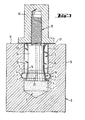
- Fig. 1 zeigt im Schnitt einen Kolben mit eingesetzter Spannhülse und aufgesetztem Zentrieraufsatz,
- Fig. 2 den Kolben mit Zentrieraufsatz und Spannhülse im noch nicht eingesetzten Zustand,
- Fig. 3 einen Kolben mit eingesetzter Spannhülse und daran angreifender Kolbenstange,
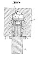
- Fig. 4 den gleichen Kolben nach dem Wenden, der Klebstoffverteilung, nach der Aushärtung des Klebers, angeschraubt an die Kolbenstange.
- Auf den Zentrieraufsatz 1, der, wie Figuren 1 und 2 zu entnehmen ist, mit einem Gewindezapfen 18 versehen ist, ist die Spannhülse 2 aufgesteckt, die von dem Konus 5 gehalten wird. Der Konus 5 weist ein Innengewinde auf, seine Kegelfläche 19 ist mit Rändelung 23 aufgerauht, um beim Eindrehen des Gewindezapfens 18 die erforderliche Reibung zwischen der Spannhülse 2 und der Kegelfläche 19 zu erzeugen. Eine ähnliche Längsrändelung 22 ist auch oben an der Spannhülse 2 vorgesehen.
- Das Sackloch 8 wird bis ungefähr Mitte der Ringnut 3 mit Kleber 7 gefüllt, bevor der Zentrieraufsatz 1 mit der Spannhülse 2 eingebracht wird. Die Schenkel 12 der Spannhülse-2 verjüngen sich in Richtung des Konus 5 und tragen an ihrem äußeren Ende einen Ansatz 4. Durch Drehen des Zentrieraufsatzes 1 mittels der Schlüsselfläche 1' wird der Ansatz 4 in die Ringnut 3 des Kolbens 6 eingedrückt. Dabei liegt der Zentrieraufsatz 1 mit seinem Bund 2o über eine Dichtung 21 auf der Kolbenstirnfläche 11 auf und wird durch den Bund 9 auf der Kolbenmantelfläche 1o geführt. Die Spannhülse 2 wird dadurch zentriert, gleichzeitig ergibt sich eine schlüssige Verbindung über die Ansätze 4 mit dem Kolben 6. Wie die Figuren 2 und 4 zeigen, kann der Konus 5 die Form einer Konusmutter 15 mit verlängertem Innengewindeteil aufweisen. Alternativ dazu ist es jedoch möglich, wie dieFigur 3 zeigt, statt der Konusmutter 15 eine Spannschraube 16 mit Schaft 24 einzusetzen, deren Kopf als Konus 5 ausgebildet ist.
- Figur 4 zeigt den Kolben 6 in um 180° gedrehter Position. Der Kleber 7 fließt dabei vom Grund des Sackloches 8 heraus und füllt sowohl die Ringnut 3 als auch den Bereich der Längsrändelung 22.
- Nach Abbinden des Klebers 7, der die Schenkel 12 der Spannhülse 2 und die Spannschraube 6, bzw. die Konusmutter 15 in ihrer Lage fixiert, wird die Kolbenstange 17 an den Kolben 6 angschraubt. Zwischen den Schenkeln 12 und der Spannschraube 16, 24 bzw. der Konusmutter 15 befindet sich jetzt ein Freiraum 14, der durch Erwärmung auftretende Verformung des Schenkels 12 aufnehmen kann. Das Auslaufen des Klebers 7 in der Abbindeposition nach Figur 4 verhindert die Dichtung 21.
Claims (10)
Priority Applications (3)
| Application Number | Priority Date | Filing Date | Title |
|---|---|---|---|
| AT85104328T ATE35023T1 (de) | 1985-04-10 | 1985-04-10 | Verfahren zum herstellen von kolben aus sproeden hartstoffen. |
| DE8585104328T DE3563241D1 (en) | 1985-04-10 | 1985-04-10 | Production method for pistons of brittle material |
| EP85104328A EP0197178B1 (de) | 1985-04-10 | 1985-04-10 | Verfahren zum Herstellen von Kolben aus spröden Hartstoffen |
Applications Claiming Priority (1)
| Application Number | Priority Date | Filing Date | Title |
|---|---|---|---|
| EP85104328A EP0197178B1 (de) | 1985-04-10 | 1985-04-10 | Verfahren zum Herstellen von Kolben aus spröden Hartstoffen |
Publications (2)
| Publication Number | Publication Date |
|---|---|
| EP0197178A1 true EP0197178A1 (de) | 1986-10-15 |
| EP0197178B1 EP0197178B1 (de) | 1988-06-08 |
Family
ID=8193442
Family Applications (1)
| Application Number | Title | Priority Date | Filing Date |
|---|---|---|---|
| EP85104328A Expired EP0197178B1 (de) | 1985-04-10 | 1985-04-10 | Verfahren zum Herstellen von Kolben aus spröden Hartstoffen |
Country Status (3)
| Country | Link |
|---|---|
| EP (1) | EP0197178B1 (de) |
| AT (1) | ATE35023T1 (de) |
| DE (1) | DE3563241D1 (de) |
Cited By (1)
| Publication number | Priority date | Publication date | Assignee | Title |
|---|---|---|---|---|
| CN115519074A (zh) * | 2021-06-25 | 2022-12-27 | 江苏集萃先进金属材料研究所有限公司 | 一种复合结构陶瓷型芯及其制备方法 |
Citations (4)
| Publication number | Priority date | Publication date | Assignee | Title |
|---|---|---|---|---|
| DE2511467A1 (de) * | 1975-03-15 | 1976-09-16 | Artur Fischer | Befestigungselement zum einbetonieren |
| DE2939284A1 (de) * | 1979-09-28 | 1981-04-02 | Feldmühle AG, 4000 Düsseldorf | Verfahren zum herstellen von kolben aus gesinterter oxidkeramik |
| US4475329A (en) * | 1982-07-14 | 1984-10-09 | Artur Fischer | Anchoring expansible fastener |
| GB2142413A (en) * | 1983-06-30 | 1985-01-16 | Steatite & Porcelain Prod Ltd | Plunger construction for pump |
-
1985
- 1985-04-10 EP EP85104328A patent/EP0197178B1/de not_active Expired
- 1985-04-10 DE DE8585104328T patent/DE3563241D1/de not_active Expired
- 1985-04-10 AT AT85104328T patent/ATE35023T1/de not_active IP Right Cessation
Patent Citations (4)
| Publication number | Priority date | Publication date | Assignee | Title |
|---|---|---|---|---|
| DE2511467A1 (de) * | 1975-03-15 | 1976-09-16 | Artur Fischer | Befestigungselement zum einbetonieren |
| DE2939284A1 (de) * | 1979-09-28 | 1981-04-02 | Feldmühle AG, 4000 Düsseldorf | Verfahren zum herstellen von kolben aus gesinterter oxidkeramik |
| US4475329A (en) * | 1982-07-14 | 1984-10-09 | Artur Fischer | Anchoring expansible fastener |
| GB2142413A (en) * | 1983-06-30 | 1985-01-16 | Steatite & Porcelain Prod Ltd | Plunger construction for pump |
Cited By (1)
| Publication number | Priority date | Publication date | Assignee | Title |
|---|---|---|---|---|
| CN115519074A (zh) * | 2021-06-25 | 2022-12-27 | 江苏集萃先进金属材料研究所有限公司 | 一种复合结构陶瓷型芯及其制备方法 |
Also Published As
| Publication number | Publication date |
|---|---|
| EP0197178B1 (de) | 1988-06-08 |
| ATE35023T1 (de) | 1988-06-15 |
| DE3563241D1 (en) | 1988-07-14 |
Similar Documents
| Publication | Publication Date | Title |
|---|---|---|
| DE2630344C2 (de) | Metalleinsatzbüchse | |
| DE4006028C2 (de) | Verbindungsbolzen und Anordnung aus Komponenten | |
| EP0308594B1 (de) | Spreizdübel | |
| DE2613526B2 (de) | Vorrichtung zum Spannen und genauen Zentrieren eines Werkstückes oder Werkzeuges | |
| EP0688025B1 (de) | Hochspannungsisolator aus Keramik | |
| DE2939284C2 (de) | Verfahren zum Herstellen von Kolben aus gesinterter Oxidkeramik | |
| EP0414280B1 (de) | Sägeseilverschluss | |
| AT390573B (de) | Vorrichtung zum befestigen eines walzringes auf einer walzenwelle | |
| DE2552873A1 (de) | Hydraulisches spannelement | |
| EP0197178B1 (de) | Verfahren zum Herstellen von Kolben aus spröden Hartstoffen | |
| DE3436733C2 (de) | ||
| CH681964A5 (de) | ||
| DE4204644C2 (de) | Vorrichtung zur Einstellung eines Werkzeuganschlags in einer Werkzeugspindel | |
| DE3406991A1 (de) | Verfahren zum herstellen von kolben aus sproeden hartstoffen | |
| EP0153560A2 (de) | Spannvorrichtung | |
| DE3347167C2 (de) | ||
| DE3805405A1 (de) | Saegewerkzeug | |
| DE2613192A1 (de) | Schraubensicherung | |
| EP0356575A2 (de) | Spannvorrichtung für eine Drehmaschine | |
| DE29803308U1 (de) | Profilverbindungssystem | |
| EP0220165A2 (de) | Verfahren zum Sichern eines Schraubbolzens, insbesondere eines Stiftschraubbolzens, in einer Gewindebohrung eines Werkstückes, Schraubbolzen und Werkzeug zur Durchführung des Verfahrens | |
| DE3203344A1 (de) | Kaltschmiededorn mit gewinde | |
| DE4319822A1 (de) | Vorrichtung zum Verbinden eines Körpers aus einem spröden Material mit einem Teil aus einem duktilen Material | |
| DE3338559A1 (de) | Verfahren zur befestigung eines koppelbolzens in einem stein und vorrichtungen zur durchfuehrung dieses verfahrens | |
| DE3446330A1 (de) | Wurzelstift fuer einen zahn |
Legal Events
| Date | Code | Title | Description |
|---|---|---|---|
| PUAI | Public reference made under article 153(3) epc to a published international application that has entered the european phase |
Free format text: ORIGINAL CODE: 0009012 |
|
| 17P | Request for examination filed |
Effective date: 19850426 |
|
| AK | Designated contracting states |
Kind code of ref document: A1 Designated state(s): AT BE CH DE FR GB IT LI LU NL SE |
|
| 17Q | First examination report despatched |
Effective date: 19871119 |
|
| ITF | It: translation for a ep patent filed | ||
| GRAA | (expected) grant |
Free format text: ORIGINAL CODE: 0009210 |
|
| AK | Designated contracting states |
Kind code of ref document: B1 Designated state(s): AT BE CH DE FR GB IT LI LU NL SE |
|
| REF | Corresponds to: |
Ref document number: 35023 Country of ref document: AT Date of ref document: 19880615 Kind code of ref document: T |
|
| REF | Corresponds to: |
Ref document number: 3563241 Country of ref document: DE Date of ref document: 19880714 |
|
| ET | Fr: translation filed | ||
| GBT | Gb: translation of ep patent filed (gb section 77(6)(a)/1977) | ||
| PLBE | No opposition filed within time limit |
Free format text: ORIGINAL CODE: 0009261 |
|
| STAA | Information on the status of an ep patent application or granted ep patent |
Free format text: STATUS: NO OPPOSITION FILED WITHIN TIME LIMIT |
|
| PG25 | Lapsed in a contracting state [announced via postgrant information from national office to epo] |
Ref country code: GB Effective date: 19890410 Ref country code: AT Effective date: 19890410 |
|
| PG25 | Lapsed in a contracting state [announced via postgrant information from national office to epo] |
Ref country code: SE Effective date: 19890411 |
|
| PG25 | Lapsed in a contracting state [announced via postgrant information from national office to epo] |
Ref country code: LU Free format text: LAPSE BECAUSE OF NON-PAYMENT OF DUE FEES Effective date: 19890430 Ref country code: LI Effective date: 19890430 Ref country code: CH Effective date: 19890430 Ref country code: BE Effective date: 19890430 |
|
| 26N | No opposition filed | ||
| BERE | Be: lapsed |
Owner name: FELDMUHLE A.G. Effective date: 19890430 |
|
| PG25 | Lapsed in a contracting state [announced via postgrant information from national office to epo] |
Ref country code: NL Effective date: 19891101 |
|
| GBPC | Gb: european patent ceased through non-payment of renewal fee | ||
| NLV4 | Nl: lapsed or anulled due to non-payment of the annual fee | ||
| PG25 | Lapsed in a contracting state [announced via postgrant information from national office to epo] |
Ref country code: FR Free format text: LAPSE BECAUSE OF NON-PAYMENT OF DUE FEES Effective date: 19891228 |
|
| REG | Reference to a national code |
Ref country code: CH Ref legal event code: PL |
|
| PG25 | Lapsed in a contracting state [announced via postgrant information from national office to epo] |
Ref country code: DE Effective date: 19900103 |
|
| REG | Reference to a national code |
Ref country code: FR Ref legal event code: ST |
|
| EUG | Se: european patent has lapsed |
Ref document number: 85104328.1 Effective date: 19900412 |