EP0197229B1 - Auf einen Autokarosserieprüfstand zu montierende Vorrichtung zur lokalisierten Kontrolle und eventuellen Wiederinstandsetzung - Google Patents
Auf einen Autokarosserieprüfstand zu montierende Vorrichtung zur lokalisierten Kontrolle und eventuellen Wiederinstandsetzung Download PDFInfo
- Publication number
- EP0197229B1 EP0197229B1 EP19850400684 EP85400684A EP0197229B1 EP 0197229 B1 EP0197229 B1 EP 0197229B1 EP 19850400684 EP19850400684 EP 19850400684 EP 85400684 A EP85400684 A EP 85400684A EP 0197229 B1 EP0197229 B1 EP 0197229B1
- Authority
- EP
- European Patent Office
- Prior art keywords
- control
- monitoring
- column
- rod
- fixing
- Prior art date
- Legal status (The legal status is an assumption and is not a legal conclusion. Google has not performed a legal analysis and makes no representation as to the accuracy of the status listed.)
- Expired
Links
- 238000012544 monitoring process Methods 0.000 claims 6
- 238000012806 monitoring device Methods 0.000 claims 2
- 239000006096 absorbing agent Substances 0.000 description 5
- 230000035939 shock Effects 0.000 description 5
- 238000004519 manufacturing process Methods 0.000 description 2
- 239000004579 marble Substances 0.000 description 2
- 238000011084 recovery Methods 0.000 description 2
- 241000282898 Sus scrofa Species 0.000 description 1
- 239000000470 constituent Substances 0.000 description 1
- 230000003247 decreasing effect Effects 0.000 description 1
- 238000007689 inspection Methods 0.000 description 1
- 238000000034 method Methods 0.000 description 1
- 239000013641 positive control Substances 0.000 description 1
- 238000003466 welding Methods 0.000 description 1
Images


Classifications
-
- B—PERFORMING OPERATIONS; TRANSPORTING
- B21—MECHANICAL METAL-WORKING WITHOUT ESSENTIALLY REMOVING MATERIAL; PUNCHING METAL
- B21D—WORKING OR PROCESSING OF SHEET METAL OR METAL TUBES, RODS OR PROFILES WITHOUT ESSENTIALLY REMOVING MATERIAL; PUNCHING METAL
- B21D1/00—Straightening, restoring form or removing local distortions of sheet metal or specific articles made therefrom; Stretching sheet metal combined with rolling
- B21D1/14—Straightening frame structures
-
- B—PERFORMING OPERATIONS; TRANSPORTING
- B66—HOISTING; LIFTING; HAULING
- B66F—HOISTING, LIFTING, HAULING OR PUSHING, NOT OTHERWISE PROVIDED FOR, e.g. DEVICES WHICH APPLY A LIFTING OR PUSHING FORCE DIRECTLY TO THE SURFACE OF A LOAD
- B66F3/00—Devices, e.g. jacks, adapted for uninterrupted lifting of loads
- B66F3/24—Devices, e.g. jacks, adapted for uninterrupted lifting of loads fluid-pressure operated
- B66F3/25—Constructional features
- B66F3/36—Load-engaging elements
- B66F3/38—Load-engaging elements adjustable relative to piston
Definitions
- the present invention relates to control and straightening operations of automobile bodies, for example bodies having undergone deformation following an accident.
- document FR-A-2384229 which describes an apparatus corresponding to such a system.
- the characteristics in accordance with the first part of claim 1 are known from document FR-A-2384229.
- the positive system is recognized as the most reliable and the most rigid.
- it has two notable disadvantages, namely the cost of each set of fittings, and the discomfort that a fitting mounted on a crossmember can cause in the deformed area of the vehicle. Indeed, when there is a deformation, even a slight one, and a straightening operation has to be carried out, it is necessary to dismantle the fitting before this operation in order to be able to hang and pull the damaged part, after which it is necessary to reassemble the fitting to check if the point controlled by the fitting has returned to its correct position. This therefore requires significant time.
- the aim of the present invention is to produce a control apparatus making it easier to carry out such control operations and to carry out, if necessary, a localized rectification without there being any need to dismantle the control supports and fixing of the bodywork in the vicinity of the deformed part.
- This apparatus is also designed so that its constituent elements can be produced from a limited number of standardized parts.
- the present apparatus makes it possible both to carry out the desired control operations and to carry out, if necessary, a localized recovery of a determined part of the bodywork.
- the devices constituting this apparatus can only be used for rectifications of limited importance.
- the usual straightening devices should be used or the corresponding part of the body should be changed. But in very many cases, we find us in the presence of deformations for which the devices according to the invention are sufficient.
- the apparatus according to the invention has the same advantages as the usual apparatus corresponding to the so-called "positive" control system, but without the disadvantages.
- this apparatus includes control devices which are specific to a specific type of vehicle, which allows very reliable control.
- the devices for controlling the various games required are made from a limited number of standard elements corresponding to the hollow column of each device, to its base, to the sleeve provided at the upper end, and to the mounted rod. sliding in this sleeve, only the head attached to this rod being different to be specific to each type of vehicle.
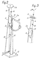
- control devices 2a one of which is shown in detail in FIGS. 2 to 5, is intended to ensure control, and possibly local recovery, of the location for fixing the upper end of a shock absorber 3 of the Mac Pherson type fitted to one of the front wheels of a motor car.
- a shock absorber 3 of the Mac Pherson type fitted to one of the front wheels of a motor car.
- the upper end of such a shock absorber is fixed, by means of a cup 5, in an opening 6 formed in the inner wall 7 of the respective front wing of the corresponding bodywork C.
- control bench 1 To carry out general or partial control of a motor vehicle body, it is fixed above the control bench 1, commonly known as “marble”, for example a bench such as that described in the patent FR- A-2423748.
- This fixing is ensured by means of several fixing fittings constituted by 2p devices of the same type as the actual control devices, that is to say the devices 2a, 2b.
- the corresponding wheels 4 of the vehicle must be removed before installing the bodywork on the test bench and fixing it on it. ci by means of a series of control devices.
- Each control device 2a is constituted by a column 10 open over its entire height, the lower end of which comprises a plate 11 provided with holes 12 spaced apart according to the same spacing module as the holes 13 provided on the side members 1a of the control bench 1, as well as on the lateral appendages 14 provided at the front end of these beams.
- each column 10 is constituted by a rolled sheet in the form of a gutter whose side walls have a decreasing width upwards, as shown in FIGS. 2 and 4.
- the column 10 carries a guide sleeve 15 housed in this end and fixed to the latter by welding.
- a control rod 16 capable of sliding inside thereof.
- immobilization means (not shown) are provided, on the other hand, preventing this rod from rotating on itself inside the guide sleeve 15.
- this rod should be arranged in a precise angular orientation to allow valid control of the position in space of the location for fixing the upper end of a shock absorber 1 of the Mac Pherson type.
- this orientation is determined by the axis XX ′ of the guide sleeve 15 which forms an angle ⁇ with respect to the vertical. This sleeve is therefore fixed in the desired orientation on the upper end of the column 10, as illustrated in FIG. 3.
- the rod 16 carries a disc 17 provided, in its center, with a projecting washer 18 for centering which is intended to be engaged inside the opening 6 provided in the part 7 of the body for fixing the upper end of a shock absorber 3 of the Mac Pherson type.
- the rod 16 At rest, the rod 16 is placed in a low position, determined by a stop 19 carried by the latter and which is then in abutment against the upper edge of the sleeve 15.
- this rod must be raised by sliding to a position for which a transverse bore 20 of this rod is brought into line with diametrical holes 21 of the guide sleeve 15.
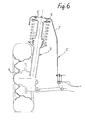
- a pin 22 then makes it possible to immobilize the rod 16 in this position for which the washer upper centering 18 must be very exactly engaged in the opening 6 of the corresponding part 7 of the body, while the disc 17 is for its part in abutment against the internal edges of this same opening, as shown in FIG. 5.
- a thrust cylinder 23 can be placed inside of it as shown in FIGS. 2 and 5, so that the head 24 of this jack comes to act on the rod 16.
- the latter serves as a thrust member against the internal face of the corresponding part 7 of the body.
- the disc 17 and the centering washer 18 can be replaced by another disc 17a capable of serving as a support member and which does not have a centering washer at its upper end.
- the device 2a according to the invention can be used again to control the straightening carried out, and to check whether from now on the location of the opening 6 corresponds to the specifications of the body to be repaired.
- the device 2a according to the invention can only be used for adjustments corresponding to deformations of limited importance. However, it is frequent that one is in the presence of such deformations. This is why in many cases this device will be sufficient and will avoid having to resort to the use of the usual body straightening devices. However, this results in an extremely significant time saving, since the use of this device avoids having to dismantle the supports of the bodywork and, moreover, the control of the straightening to be carried out can be carried out immediately with this same device.
- the body to be checked must first be fixed on the bench 1 used.
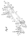
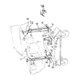
- This fixing can be ensured by means of a number of control and fixing devices according to the invention, such as 2p devices shown in FIGS. 1, 4 and 5.
- Each of these devices is of the same type as devices 2a, 2b.
- these fastening devices are specific to the particular type of vehicle to be checked and they also serve, in themselves, to check for any deformation of the bodywork to be checked.
- Each of these devices therefore consists of a column 10 open over its entire height and the lower end of which comprises a plate 11 enabling it to be fixed to the side members of the control bench 1.
- This column carries a rod 16, mounted in a sleeve 15, and which carries a head 17p capable of receiving the corresponding element 7p of the body, which can be fixed to this head, by means of one or more bolts.
- the other devices 2b, 2c, 2d, 2e, 2f, 2g and 2h, shown in fig. 1, are also designed to ensure the control of several determined points of a bodywork and possibly the fixing thereof on the corresponding marble 1, through these different points.
- each of them respond to the same general design as the devices 2a and 2p described above. Indeed each of them is constituted by a hollow column 10 open over its entire height and whose lower end is fixed on a plate 11 having holes 12 having the same spacing module, while its upper end comprises a sleeve inside which slides a rod 16.
- These devices can be used both for a simple control and a localized straightening operation. In the latter case a removable cylinder, such as the cylinder 23, is placed inside the column 10 of the corresponding device to act on the rod 16 thereof.
- figs. 7 to 12 show various examples of devices according to the invention 2h, 2i, 2j, 2k, 21, 2m whose sliding rods 16 are equipped with control heads 17h, 17i, 17j, 17k, 171, 17m of different types.
- the manufacturing cost of these is considerably reduced compared to the manufacturing cost of the specific control fittings constituting the equipment usually used for control according to the so-called "positive" system.
- the vertical axis of the upper sleeve 15 does not cross the lower plate 11 at the geometric center of the four holes thereof, nor in an arbitrary position, relative to these holes, but a quarter of the distance from the side of the square formed by the four holes.
- the sliding rods of at least some of the devices in question may have two holes 20 instead of a single one to allow two different possibilities for adjusting the height of the corresponding control head. It is also possible to provide angularly offset holes in order to be able to immobilize the control heads in different angular positions.
Landscapes
- Engineering & Computer Science (AREA)
- Mechanical Engineering (AREA)
- Life Sciences & Earth Sciences (AREA)
- Geology (AREA)
- Structural Engineering (AREA)
- Automatic Assembly (AREA)
- Vehicle Cleaning, Maintenance, Repair, Refitting, And Outriggers (AREA)
- Automobile Manufacture Line, Endless Track Vehicle, Trailer (AREA)
Claims (4)
Priority Applications (3)
| Application Number | Priority Date | Filing Date | Title |
|---|---|---|---|
| FR8319831A FR2556248B1 (fr) | 1983-12-12 | 1983-12-12 | Dispositif destine a etre monte sur un banc de controle de carrosseries d'automobile pour proceder a un controle localise et a un redressement eventuel |
| EP19850400684 EP0197229B1 (de) | 1983-12-12 | 1985-04-05 | Auf einen Autokarosserieprüfstand zu montierende Vorrichtung zur lokalisierten Kontrolle und eventuellen Wiederinstandsetzung |
| DE8585400684T DE3570373D1 (en) | 1985-04-05 | 1985-04-05 | Apparatus to be mounted on a motor vehicle body test stand for executing a localized control and possible straightening |
Applications Claiming Priority (2)
| Application Number | Priority Date | Filing Date | Title |
|---|---|---|---|
| FR8319831A FR2556248B1 (fr) | 1983-12-12 | 1983-12-12 | Dispositif destine a etre monte sur un banc de controle de carrosseries d'automobile pour proceder a un controle localise et a un redressement eventuel |
| EP19850400684 EP0197229B1 (de) | 1983-12-12 | 1985-04-05 | Auf einen Autokarosserieprüfstand zu montierende Vorrichtung zur lokalisierten Kontrolle und eventuellen Wiederinstandsetzung |
Publications (2)
| Publication Number | Publication Date |
|---|---|
| EP0197229A1 EP0197229A1 (de) | 1986-10-15 |
| EP0197229B1 true EP0197229B1 (de) | 1989-05-24 |
Family
ID=26099971
Family Applications (1)
| Application Number | Title | Priority Date | Filing Date |
|---|---|---|---|
| EP19850400684 Expired EP0197229B1 (de) | 1983-12-12 | 1985-04-05 | Auf einen Autokarosserieprüfstand zu montierende Vorrichtung zur lokalisierten Kontrolle und eventuellen Wiederinstandsetzung |
Country Status (2)
| Country | Link |
|---|---|
| EP (1) | EP0197229B1 (de) |
| FR (1) | FR2556248B1 (de) |
Families Citing this family (8)
| Publication number | Priority date | Publication date | Assignee | Title |
|---|---|---|---|---|
| FR2556248B1 (fr) * | 1983-12-12 | 1989-08-18 | Celette Sa | Dispositif destine a etre monte sur un banc de controle de carrosseries d'automobile pour proceder a un controle localise et a un redressement eventuel |
| FR2582238B2 (fr) * | 1985-05-21 | 1992-06-12 | Celette Sa | Dispositif destine a etre monte sur un banc de controle de carrosseries d'automobile pour proceder a un controle localise et a un redressement eventuel |
| IT1186211B (it) * | 1985-11-19 | 1987-11-18 | Bike Mach Srl | Macchina automatica per il controllo e la squdratura di telai per bicibletta |
| US4781045A (en) * | 1986-04-01 | 1988-11-01 | Celette S.A. | Vehicle checking and straightening equipment with interchangeable operating heads |
| IT1205505B (it) * | 1986-07-16 | 1989-03-23 | Linea A Srl | Morsetto di ancoraggio per raddrizzatura carrozzeria di automobile incidentate,particolarmente per alloggiamenti in lamieri di teste delle sospensioni mac pherson |
| DE3835270A1 (de) * | 1988-10-15 | 1990-04-19 | Celette Gmbh | Terminal-richtwinkelsatzteil fuer eine richtbank zum richten und wiederherstellen beschaedigter karosserien von kraftfahrzeugen |
| BE1007009A3 (nl) * | 1993-04-21 | 1995-02-14 | Atlantic Naamloze Vennootschap | Verbeterde kolom voor richtbank. |
| CN110800025A (zh) * | 2017-06-26 | 2020-02-14 | 威图纳有限公司 | 用于设计定制的车辆维修配置的系统和方法 |
Family Cites Families (7)
| Publication number | Priority date | Publication date | Assignee | Title |
|---|---|---|---|---|
| US1905624A (en) * | 1930-02-27 | 1933-04-25 | Dwork Max | Jack |
| US3275298A (en) * | 1964-06-22 | 1966-09-27 | Steadman Ind Ltd | Demountable containers provided with jack legs for raising and lowering the same |
| US3709467A (en) * | 1970-11-27 | 1973-01-09 | J Mann | Self contained adjustable support assemblies to support, raise, and lower a mobile living facility with respect to both a vehicle and the ground |
| DE2319127A1 (de) * | 1973-04-16 | 1974-10-17 | Rmi Gmbh & Co Kg | Einrichtung zum spannen von kanalstreben |
| FR2384229A1 (fr) * | 1977-03-16 | 1978-10-13 | Olsson Erik Allan | Procede pour la mesure de cadres ou chassis de vehicules et dispositif pour l'application de ce procede |
| IT1085465B (it) * | 1977-07-19 | 1985-05-28 | Ballero Carlo | Struttura modulare di riscontro ad assetto variabile,per il ripristino di autovetture deformate in seguito a incidenti |
| FR2556248B1 (fr) * | 1983-12-12 | 1989-08-18 | Celette Sa | Dispositif destine a etre monte sur un banc de controle de carrosseries d'automobile pour proceder a un controle localise et a un redressement eventuel |
-
1983
- 1983-12-12 FR FR8319831A patent/FR2556248B1/fr not_active Expired
-
1985
- 1985-04-05 EP EP19850400684 patent/EP0197229B1/de not_active Expired
Also Published As
| Publication number | Publication date |
|---|---|
| FR2556248B1 (fr) | 1989-08-18 |
| FR2556248A1 (fr) | 1985-06-14 |
| EP0197229A1 (de) | 1986-10-15 |
Similar Documents
| Publication | Publication Date | Title |
|---|---|---|
| EP0197229B1 (de) | Auf einen Autokarosserieprüfstand zu montierende Vorrichtung zur lokalisierten Kontrolle und eventuellen Wiederinstandsetzung | |
| EP0311535A1 (de) | Richtbank für die Montage, Überwachung und Reparatur, insbesondere von Karrosserien von Kraftfahrzeugen | |
| FR2900605A1 (fr) | Procede de fabrication d'un mecanisme d'articulation pour siege de vehicule, mecanisme d'articulation fabrique selon un tel procede et siege de vehicule comprenant un tel mecanisme d'articulation | |
| BE543618A (de) | ||
| FR2941208A1 (fr) | Gabarit de montage de supports d'aile sur la caisse d'un vehicule et procede associe. | |
| EP0122200A1 (de) | Montagevorrichtung für eine Fahrzeugkarosserie auf einer Kontrollplatte | |
| FR2581634A1 (fr) | Chariot elevateur, notamment pour la manipulation de vehicules automobiles et de marbres de redressement de vehicules | |
| FR3128145A1 (fr) | Installation pour le maintien d’un engin roulant à deux ou trois roues en vue d’une intervention sur ledit engin | |
| EP0419383A1 (de) | Vorrichtung zum Befestigen eines Fahrzeuges und zum Justieren seiner Position auf einem Rahmen zwecks Reparatur des genannten Fahrzeuges | |
| FR2997876A1 (fr) | Machine pour assembler deux pieces en tole par pliage du bord de l'une des pieces sur l'autre piece, comportant des moyens de reglage | |
| EP2161184A1 (de) | Kontroll- und Regulierverfahren der Montage eines Fensters in der Tür eines Coupé- oder Cabriolet-Fahrzeugs | |
| FR2667275A1 (fr) | Dispositif de fixation d'un radiateur de refroidissement d'un moteur de vehicule automobile. | |
| EP0475860A1 (de) | Vorrichtung zum Befestigen einer Klemmeinrichtung zum Festhalten des Unterteils eines Fahrzeugs auf einer Richtbank zur Reparierung von Fahrzeugkarrosserien | |
| EP0581627B1 (de) | Verfahren zur Befestigung einer Fahrzeugachse am Rahmen eines Fahrzeugs | |
| FR2546834A1 (fr) | Appareil pour verifier et reparer la carrosserie des vehicules automobiles | |
| FR2591328A1 (fr) | Plate-forme de controle et/ou de reparation des carrosseries et chassis de vehicules automobiles | |
| FR2794419A1 (fr) | Ensemble de colonne de direction | |
| FR2555563A1 (fr) | Bloc tournant pour vehicule de travail en hauteur | |
| FR2882022A1 (fr) | Dispositif de fixation automatique d'une planche de bord sur une caisse de vehicule automobile | |
| FR2582238A2 (fr) | Dispositif destine a etre monte sur un banc de controle de carrosseries d'automobile pour proceder a un controle localise et a un redressement eventuel | |
| WO2017191376A1 (fr) | Interface de montage d'une colonne de direction et procede de montage associe | |
| FR2809073A1 (fr) | Face avant pour vehicule automobile et bloc avant correspondant | |
| FR2596508A1 (fr) | Gabarit de mesure pour installation de redressement de chassis de vehicules | |
| FR3146653A1 (fr) | Gabarit de montage d’une charnière de porte de véhicule automobile. | |
| FR3075751A1 (fr) | Procede d'assemblage becquet-hayon |
Legal Events
| Date | Code | Title | Description |
|---|---|---|---|
| PUAI | Public reference made under article 153(3) epc to a published international application that has entered the european phase |
Free format text: ORIGINAL CODE: 0009012 |
|
| AK | Designated contracting states |
Kind code of ref document: A1 Designated state(s): BE DE GB IT SE |
|
| 17P | Request for examination filed |
Effective date: 19861126 |
|
| 17Q | First examination report despatched |
Effective date: 19871217 |
|
| ITF | It: translation for a ep patent filed | ||
| GRAA | (expected) grant |
Free format text: ORIGINAL CODE: 0009210 |
|
| AK | Designated contracting states |
Kind code of ref document: B1 Designated state(s): BE DE GB IT SE |
|
| REF | Corresponds to: |
Ref document number: 3570373 Country of ref document: DE Date of ref document: 19890629 |
|
| GBT | Gb: translation of ep patent filed (gb section 77(6)(a)/1977) | ||
| PLBI | Opposition filed |
Free format text: ORIGINAL CODE: 0009260 |
|
| 26 | Opposition filed |
Opponent name: BLACKHAWK GMBH Effective date: 19900223 |
|
| ITTA | It: last paid annual fee | ||
| PGFP | Annual fee paid to national office [announced via postgrant information from national office to epo] |
Ref country code: GB Payment date: 19920225 Year of fee payment: 8 |
|
| PG25 | Lapsed in a contracting state [announced via postgrant information from national office to epo] |
Ref country code: GB Effective date: 19930405 |
|
| PGFP | Annual fee paid to national office [announced via postgrant information from national office to epo] |
Ref country code: SE Payment date: 19930413 Year of fee payment: 9 |
|
| GBPC | Gb: european patent ceased through non-payment of renewal fee |
Effective date: 19930405 |
|
| PGFP | Annual fee paid to national office [announced via postgrant information from national office to epo] |
Ref country code: DE Payment date: 19940311 Year of fee payment: 10 |
|
| PGFP | Annual fee paid to national office [announced via postgrant information from national office to epo] |
Ref country code: BE Payment date: 19940324 Year of fee payment: 10 |
|
| PG25 | Lapsed in a contracting state [announced via postgrant information from national office to epo] |
Ref country code: SE Effective date: 19940406 |
|
| PLBN | Opposition rejected |
Free format text: ORIGINAL CODE: 0009273 |
|
| STAA | Information on the status of an ep patent application or granted ep patent |
Free format text: STATUS: OPPOSITION REJECTED |
|
| EUG | Se: european patent has lapsed |
Ref document number: 85400684.8 Effective date: 19941110 |
|
| 27O | Opposition rejected |
Effective date: 19941123 |
|
| PG25 | Lapsed in a contracting state [announced via postgrant information from national office to epo] |
Ref country code: BE Effective date: 19950430 |
|
| BERE | Be: lapsed |
Owner name: S.A. CELETTE Effective date: 19950430 |
|
| PG25 | Lapsed in a contracting state [announced via postgrant information from national office to epo] |
Ref country code: DE Effective date: 19960103 |
|
| APAH | Appeal reference modified |
Free format text: ORIGINAL CODE: EPIDOSCREFNO |