EP0197232A1 - Impulsgesteuertes elektromagnetisches Ventil - Google Patents
Impulsgesteuertes elektromagnetisches Ventil Download PDFInfo
- Publication number
- EP0197232A1 EP0197232A1 EP85810159A EP85810159A EP0197232A1 EP 0197232 A1 EP0197232 A1 EP 0197232A1 EP 85810159 A EP85810159 A EP 85810159A EP 85810159 A EP85810159 A EP 85810159A EP 0197232 A1 EP0197232 A1 EP 0197232A1
- Authority
- EP
- European Patent Office
- Prior art keywords
- elements
- valve according
- engaged
- valve
- plates
- Prior art date
- Legal status (The legal status is an assumption and is not a legal conclusion. Google has not performed a legal analysis and makes no representation as to the accuracy of the status listed.)
- Granted
Links
- 230000005291 magnetic effect Effects 0.000 claims abstract description 9
- 239000000463 material Substances 0.000 claims abstract description 4
- 239000012530 fluid Substances 0.000 claims description 5
- 239000000696 magnetic material Substances 0.000 claims description 4
- 238000004804 winding Methods 0.000 claims description 2
- 238000007789 sealing Methods 0.000 abstract 1
- 230000000694 effects Effects 0.000 description 2
- 238000006073 displacement reaction Methods 0.000 description 1
- 230000005294 ferromagnetic effect Effects 0.000 description 1
- 239000003302 ferromagnetic material Substances 0.000 description 1
- 230000004907 flux Effects 0.000 description 1
- 238000009434 installation Methods 0.000 description 1
- 238000004519 manufacturing process Methods 0.000 description 1
- 230000000717 retained effect Effects 0.000 description 1
Images
Classifications
-
- F—MECHANICAL ENGINEERING; LIGHTING; HEATING; WEAPONS; BLASTING
- F16—ENGINEERING ELEMENTS AND UNITS; GENERAL MEASURES FOR PRODUCING AND MAINTAINING EFFECTIVE FUNCTIONING OF MACHINES OR INSTALLATIONS; THERMAL INSULATION IN GENERAL
- F16K—VALVES; TAPS; COCKS; ACTUATING-FLOATS; DEVICES FOR VENTING OR AERATING
- F16K31/00—Actuating devices; Operating means; Releasing devices
- F16K31/02—Actuating devices; Operating means; Releasing devices electric; magnetic
- F16K31/06—Actuating devices; Operating means; Releasing devices electric; magnetic using a magnet, e.g. diaphragm valves, cutting off by means of a liquid
- F16K31/0603—Multiple-way valves
- F16K31/061—Sliding valves
- F16K31/0613—Sliding valves with cylindrical slides
-
- F—MECHANICAL ENGINEERING; LIGHTING; HEATING; WEAPONS; BLASTING
- F16—ENGINEERING ELEMENTS AND UNITS; GENERAL MEASURES FOR PRODUCING AND MAINTAINING EFFECTIVE FUNCTIONING OF MACHINES OR INSTALLATIONS; THERMAL INSULATION IN GENERAL
- F16K—VALVES; TAPS; COCKS; ACTUATING-FLOATS; DEVICES FOR VENTING OR AERATING
- F16K31/00—Actuating devices; Operating means; Releasing devices
- F16K31/02—Actuating devices; Operating means; Releasing devices electric; magnetic
- F16K31/06—Actuating devices; Operating means; Releasing devices electric; magnetic using a magnet, e.g. diaphragm valves, cutting off by means of a liquid
- F16K31/0603—Multiple-way valves
- F16K31/0606—Multiple-way valves fluid passing through the solenoid coil
-
- F—MECHANICAL ENGINEERING; LIGHTING; HEATING; WEAPONS; BLASTING
- F16—ENGINEERING ELEMENTS AND UNITS; GENERAL MEASURES FOR PRODUCING AND MAINTAINING EFFECTIVE FUNCTIONING OF MACHINES OR INSTALLATIONS; THERMAL INSULATION IN GENERAL
- F16K—VALVES; TAPS; COCKS; ACTUATING-FLOATS; DEVICES FOR VENTING OR AERATING
- F16K31/00—Actuating devices; Operating means; Releasing devices
- F16K31/02—Actuating devices; Operating means; Releasing devices electric; magnetic
- F16K31/06—Actuating devices; Operating means; Releasing devices electric; magnetic using a magnet, e.g. diaphragm valves, cutting off by means of a liquid
- F16K31/0603—Multiple-way valves
- F16K31/061—Sliding valves
- F16K31/0617—Sliding valves with flat slides
-
- F—MECHANICAL ENGINEERING; LIGHTING; HEATING; WEAPONS; BLASTING
- F16—ENGINEERING ELEMENTS AND UNITS; GENERAL MEASURES FOR PRODUCING AND MAINTAINING EFFECTIVE FUNCTIONING OF MACHINES OR INSTALLATIONS; THERMAL INSULATION IN GENERAL
- F16K—VALVES; TAPS; COCKS; ACTUATING-FLOATS; DEVICES FOR VENTING OR AERATING
- F16K31/00—Actuating devices; Operating means; Releasing devices
- F16K31/02—Actuating devices; Operating means; Releasing devices electric; magnetic
- F16K31/06—Actuating devices; Operating means; Releasing devices electric; magnetic using a magnet, e.g. diaphragm valves, cutting off by means of a liquid
- F16K31/0603—Multiple-way valves
- F16K31/0624—Lift valves
-
- Y—GENERAL TAGGING OF NEW TECHNOLOGICAL DEVELOPMENTS; GENERAL TAGGING OF CROSS-SECTIONAL TECHNOLOGIES SPANNING OVER SEVERAL SECTIONS OF THE IPC; TECHNICAL SUBJECTS COVERED BY FORMER USPC CROSS-REFERENCE ART COLLECTIONS [XRACs] AND DIGESTS
- Y10—TECHNICAL SUBJECTS COVERED BY FORMER USPC
- Y10T—TECHNICAL SUBJECTS COVERED BY FORMER US CLASSIFICATION
- Y10T137/00—Fluid handling
- Y10T137/8593—Systems
- Y10T137/86493—Multi-way valve unit
- Y10T137/86574—Supply and exhaust
- Y10T137/86622—Motor-operated
-
- Y—GENERAL TAGGING OF NEW TECHNOLOGICAL DEVELOPMENTS; GENERAL TAGGING OF CROSS-SECTIONAL TECHNOLOGIES SPANNING OVER SEVERAL SECTIONS OF THE IPC; TECHNICAL SUBJECTS COVERED BY FORMER USPC CROSS-REFERENCE ART COLLECTIONS [XRACs] AND DIGESTS
- Y10—TECHNICAL SUBJECTS COVERED BY FORMER USPC
- Y10T—TECHNICAL SUBJECTS COVERED BY FORMER US CLASSIFICATION
- Y10T137/00—Fluid handling
- Y10T137/8593—Systems
- Y10T137/86493—Multi-way valve unit
- Y10T137/86879—Reciprocating valve unit
- Y10T137/86895—Plural disk or plug
Definitions
- Valves with pulsed electromagnetic control comprising a body delimiting a chamber in which a movable core forming a shutter can be moved under the action of a magnetic field produced by an electrical winding, this shutter member cooperating with at least one seat to control the passage of a fluid between said chamber and a connection orifice.
- Valves of this kind are generally used to obtain a flow adjustment, this adjustment being obtained by sending pulses to open the valve and respectively close it, the ratio of the opening and closing times and / or the frequency being chosen for get the desired flow.
- the stroke of the shutter member be defined with precision, of the order of a few microns.
- the value of this stroke must not change during a very high number of cycles, of the order of 10 to 10.
- the magnetic remanence effect is very low, so as not to delay the return of the magnetic core controlling the shutter.
- the object of the invention is to improve the precision and reliability of the valves of the type described, by elements which are simple to manufacture and easy to assemble, while respecting the above-mentioned requirements.
- the valve which is the subject of the invention is characterized in that the seat consists of a plate of non-magnetic material applied to a support, the material of the plate having a hardness at least equal to that of the support.
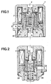
- Figure 1 is an axial section of the embodiment.
- Figure 2 is a similar section of the first variant.
- the valve according to FIG. 1 is a three-way valve with pulsed electromagnetic control. It comprises a body 1 made of ferromagnetic material, having two connection orifices 2 and 3. The body 1 is closed at its lower part by a plug 4 having a third connection orifice 5.
- the body 1 has a housing 6 in which is disposed an electric coil 7 which is pushed upwards by an annular ferromagnetic part 8, subjected to the action of a spring 9 constituted by a conical washer. This spring 9 bears against the plug 4, the axial position of which can be adjusted by screwing thanks to the thread 10.
- the plate 15 is constituted by a washer made of non-magnetic material, having a hardness at least equal to that of the body 1 against which it bears upwards.
- the plate 16 is constituted by a washer identical to the plate 15.
- the element 11 has a tubular upper portion of circular section 18, slidably engaged in a bore extending the connection orifice 2. This bore is provided in a pole portion 19 of the body 1, this portion constituting a magnetic pole of the valve . The role of this pole is to attract a magnetic core 20 which is mounted to slide freely on the element 11.
- the core 20 bears in leaktight manner against the plate 15 and, for this purpose, it is provided with a circular rib 21.
- the core 20 cuts the communication between an annular chamber 23, disposed inside the core 20, and an outer annular chamber 24, surrounding the core 20.
- the annular chamber 23 communicates with the connection orifice 2 by an elbow passage 25, formed in the element 11, while the chamber 24 communicates with the connection orifice 3 through a passage 26 provided in the annular part 8.
- the chamber 24 is placed in communication with the connection orifice 5 by a bent passage 27 provided in element 12.
- This element 12 also has a tubular portion engaged in a bore extending the connection orifice 5.
- the magnetic attraction ceases and the core 20 is brought back by a return spring 28 against the plate 16 to close the communication between the connection orifices 3 and 5.
- the seal against the plate 16 is also obtained by a circular rib provided at the base of the core 20.
- the thickness of the plate 15 made of non-magnetic material makes it possible to determine with a high accuracy the air gap that it is desired to obtain between the core 20 in the attracted position and the pole portion 19. This air gap prevents the core 20 from sticking against the portion 19 and allows a rapid return under the effect of the spring 28.
- the stroke of the core 20 between these two closed positions is adjusted by simply screwing the plug 4 into the body 1.
- the rib 21 is surrounded by a second rib 22 intended to facilitate the passage of the magnetic flux.
- FIG. 2 represents a simplified variant which retains the same principles as FIG. 1, in the case of a two-way valve with a normally open position.
- the communication between the two channels is closed between the core 20 and the pole portion 19 provided with the plate 15.
- the two elements 11 and 12 have been replaced by a single piece 30 with a tubular extension engaged in the 'connection orifice 2 and a circular rib 13 for applying the plate 15 against the pole portion 19.
- This part 30 is pushed upwards by a spring 31, disposed in a blind housing of a plug 32.
- the latter is screwed into a closing part 33 which is crimped in the body 1 by a flange 34.
- the passage of the fluid between the connection orifices 2 and 3 is facilitated by longitudinal grooves 35, provided in the external part of the core 20.
Landscapes
- Engineering & Computer Science (AREA)
- General Engineering & Computer Science (AREA)
- Mechanical Engineering (AREA)
- Magnetically Actuated Valves (AREA)
- External Artificial Organs (AREA)
- Infusion, Injection, And Reservoir Apparatuses (AREA)
- Multiple-Way Valves (AREA)
Priority Applications (5)
| Application Number | Priority Date | Filing Date | Title |
|---|---|---|---|
| DE8585810159T DE3571269D1 (en) | 1985-04-11 | 1985-04-11 | Pulse-controlled electromagnetic valve |
| DE198585810159T DE197232T1 (de) | 1985-04-11 | 1985-04-11 | Impulsgesteuertes elektromagnetisches ventil. |
| EP85810159A EP0197232B1 (de) | 1985-04-11 | 1985-04-11 | Impulsgesteuertes elektromagnetisches Ventil |
| US06/849,923 US4655249A (en) | 1985-04-11 | 1986-04-09 | Electromagnetic valve |
| JP61083192A JPH0726698B2 (ja) | 1985-04-11 | 1986-04-10 | 電磁弁 |
Applications Claiming Priority (1)
| Application Number | Priority Date | Filing Date | Title |
|---|---|---|---|
| EP85810159A EP0197232B1 (de) | 1985-04-11 | 1985-04-11 | Impulsgesteuertes elektromagnetisches Ventil |
Publications (2)
| Publication Number | Publication Date |
|---|---|
| EP0197232A1 true EP0197232A1 (de) | 1986-10-15 |
| EP0197232B1 EP0197232B1 (de) | 1989-06-28 |
Family
ID=8194638
Family Applications (1)
| Application Number | Title | Priority Date | Filing Date |
|---|---|---|---|
| EP85810159A Expired EP0197232B1 (de) | 1985-04-11 | 1985-04-11 | Impulsgesteuertes elektromagnetisches Ventil |
Country Status (4)
| Country | Link |
|---|---|
| US (1) | US4655249A (de) |
| EP (1) | EP0197232B1 (de) |
| JP (1) | JPH0726698B2 (de) |
| DE (2) | DE197232T1 (de) |
Cited By (3)
| Publication number | Priority date | Publication date | Assignee | Title |
|---|---|---|---|---|
| WO2000028206A1 (en) * | 1998-11-11 | 2000-05-18 | Invent Engineering Pty Ltd | Improved solenoid valve |
| FR2834378A1 (fr) * | 2001-12-28 | 2003-07-04 | Peugeot Citroen Automobiles Sa | Electrovanne a course de deplacement des noyaux non limitee par le dimensionnement des bobines |
| CN112460321A (zh) * | 2021-01-11 | 2021-03-09 | 福鼎市鑫龙机械部件有限公司 | 使用滑阀控制的活塞式电磁脉冲阀、控制阀体及其工作方法 |
Families Citing this family (28)
| Publication number | Priority date | Publication date | Assignee | Title |
|---|---|---|---|---|
| DE3802648A1 (de) * | 1988-01-29 | 1989-08-10 | Mainz Gmbh Feinmech Werke | Elektromagnetisch betaetigtes, hydraulisches schnellschaltventil |
| DE3814156A1 (de) * | 1988-04-27 | 1989-11-09 | Mesenich Gerhard | Pulsmoduliertes hydraulikventil |
| US4917150A (en) * | 1988-07-29 | 1990-04-17 | Colt Industries Inc. | Solenoid operated pressure control valve |
| DE3834447A1 (de) * | 1988-10-10 | 1990-04-12 | Mesenich Gerhard | Elektromagnetisches einspritzventil und verfahren zu dessen herstellung |
| JPH0616175Y2 (ja) * | 1988-12-07 | 1994-04-27 | 本田技研工業株式会社 | 電磁弁 |
| DE3844453C2 (de) * | 1988-12-31 | 1996-11-28 | Bosch Gmbh Robert | Ventil zum dosierten Zumischen von verflüchtigtem Kraftstoff zum Kraftstoffluftgemisch einer Brennkraftmaschine |
| US5114116A (en) * | 1989-12-07 | 1992-05-19 | Feinmechanische Werke Mainz Gmbh | Electromagnetically actuated quick-action switching valve |
| US5199459A (en) * | 1991-05-08 | 1993-04-06 | Valve Tech, Inc. | Dual series valve |
| US5150879A (en) * | 1991-05-08 | 1992-09-29 | Valve Tech, Inc. | Thruster valve |
| US5121769A (en) * | 1991-05-30 | 1992-06-16 | Coltec Industries Inc. | Solenoid operated pressure regulating valve |
| US5217047A (en) * | 1991-05-30 | 1993-06-08 | Coltec Industries Inc. | Solenoid operated pressure regulating valve |
| US5184644A (en) * | 1991-05-30 | 1993-02-09 | Coltec Industries Inc. | Solenoid operated pressure regulating valve |
| EP0580877B1 (de) * | 1991-07-09 | 1995-08-30 | Honeywell Lucifer Sa | Vorrichtung zur Druckregelung |
| US5218996A (en) * | 1992-04-06 | 1993-06-15 | Fasco Controls Corporation | Three-way three-position solenoid valve |
| IT1260476B (it) * | 1992-05-28 | 1996-04-09 | Dispositivo azionatore a comando elettromagnetico in particolare per valvole ed applicazioni elettroidrauliche | |
| US5374029A (en) * | 1992-06-26 | 1994-12-20 | Wright Components, Inc. | Solenoid flow control valve and frictionless plunger assembly |
| US5954312A (en) * | 1996-01-31 | 1999-09-21 | Siemens Automotive Corporation | Groove means in a fuel injector valve seat |
| JP3901787B2 (ja) * | 1997-03-19 | 2007-04-04 | 株式会社日立製作所 | 液圧制御弁 |
| US6523570B2 (en) * | 2000-05-04 | 2003-02-25 | Parker-Hannifin Corp. | Manifold for valve assembly |
| US6792975B2 (en) * | 2001-05-24 | 2004-09-21 | Borgwarner Inc. | Pulse-width modulated solenoid valve including axial stop spool valve |
| US6588726B2 (en) * | 2001-07-13 | 2003-07-08 | Eaton Corporation | Load bearing solenoid operated valve and method of making same |
| JP2003145153A (ja) * | 2001-11-13 | 2003-05-20 | Sugano Minoru | 電解水の製造方法および製造装置 |
| US6811135B2 (en) * | 2002-10-24 | 2004-11-02 | Eaton Corporation | Solenoid operated sleeve valve |
| JP4626609B2 (ja) * | 2006-12-12 | 2011-02-09 | トヨタ自動車株式会社 | 流体供給装置 |
| JP5711628B2 (ja) * | 2011-07-28 | 2015-05-07 | 日立オートモティブシステムズステアリング株式会社 | ソレノイドバルブ、ソレノイドおよび可変容量ポンプ |
| DE102014003381A1 (de) | 2014-03-06 | 2015-09-10 | Wabco Gmbh | Magnetventil |
| WO2019222832A1 (en) * | 2018-05-25 | 2019-11-28 | Obotics Inc. | Electromagnetically actuated fluidic valves and switches |
| CN114645949A (zh) * | 2022-03-02 | 2022-06-21 | 中国航空工业集团公司上海航空测控技术研究所 | 一种应用于航空机载氧气系统上的电磁阀门 |
Citations (4)
| Publication number | Priority date | Publication date | Assignee | Title |
|---|---|---|---|---|
| CH264710A (de) * | 1948-05-12 | 1949-10-31 | Bbc Brown Boveri & Cie | Elektropneumatisches Ventil für grosse Schalthäufigkeit. |
| US2860850A (en) * | 1953-05-25 | 1958-11-18 | Garrett Corp | Solenoid valve |
| US4005733A (en) * | 1975-11-17 | 1977-02-01 | General Motors Corporation | Pressure control valve |
| EP0135474A1 (de) * | 1983-08-19 | 1985-03-27 | Honeywell Lucifer Sa | Elektromagnetisches Ventil |
Family Cites Families (3)
| Publication number | Priority date | Publication date | Assignee | Title |
|---|---|---|---|---|
| US3285285A (en) * | 1964-02-27 | 1966-11-15 | Koontz Wagner Electric Company | Valve |
| US3588039A (en) * | 1969-09-05 | 1971-06-28 | Bolt Associates Inc | Solenoid valve structures and systems |
| US4531708A (en) * | 1984-08-21 | 1985-07-30 | Honeywell Lucifer Sa | Solenoid valve |
-
1985
- 1985-04-11 DE DE198585810159T patent/DE197232T1/de active Pending
- 1985-04-11 EP EP85810159A patent/EP0197232B1/de not_active Expired
- 1985-04-11 DE DE8585810159T patent/DE3571269D1/de not_active Expired
-
1986
- 1986-04-09 US US06/849,923 patent/US4655249A/en not_active Expired - Fee Related
- 1986-04-10 JP JP61083192A patent/JPH0726698B2/ja not_active Expired - Fee Related
Patent Citations (4)
| Publication number | Priority date | Publication date | Assignee | Title |
|---|---|---|---|---|
| CH264710A (de) * | 1948-05-12 | 1949-10-31 | Bbc Brown Boveri & Cie | Elektropneumatisches Ventil für grosse Schalthäufigkeit. |
| US2860850A (en) * | 1953-05-25 | 1958-11-18 | Garrett Corp | Solenoid valve |
| US4005733A (en) * | 1975-11-17 | 1977-02-01 | General Motors Corporation | Pressure control valve |
| EP0135474A1 (de) * | 1983-08-19 | 1985-03-27 | Honeywell Lucifer Sa | Elektromagnetisches Ventil |
Cited By (4)
| Publication number | Priority date | Publication date | Assignee | Title |
|---|---|---|---|---|
| WO2000028206A1 (en) * | 1998-11-11 | 2000-05-18 | Invent Engineering Pty Ltd | Improved solenoid valve |
| FR2834378A1 (fr) * | 2001-12-28 | 2003-07-04 | Peugeot Citroen Automobiles Sa | Electrovanne a course de deplacement des noyaux non limitee par le dimensionnement des bobines |
| CN112460321A (zh) * | 2021-01-11 | 2021-03-09 | 福鼎市鑫龙机械部件有限公司 | 使用滑阀控制的活塞式电磁脉冲阀、控制阀体及其工作方法 |
| CN112460321B (zh) * | 2021-01-11 | 2022-08-12 | 福鼎市鑫龙机械部件有限公司 | 使用滑阀控制的活塞式电磁脉冲阀、控制阀体及其工作方法 |
Also Published As
| Publication number | Publication date |
|---|---|
| DE3571269D1 (en) | 1989-08-03 |
| EP0197232B1 (de) | 1989-06-28 |
| DE197232T1 (de) | 1987-06-11 |
| JPS61248976A (ja) | 1986-11-06 |
| US4655249A (en) | 1987-04-07 |
| JPH0726698B2 (ja) | 1995-03-29 |
Similar Documents
| Publication | Publication Date | Title |
|---|---|---|
| EP0197232B1 (de) | Impulsgesteuertes elektromagnetisches Ventil | |
| EP0263863B1 (de) | Ventil mit hoher zuverlässigkeit | |
| FR2781529A1 (fr) | Injecteur de carburant equipe d'une soupape de commande amont et procede de realisation | |
| EP1610045A1 (de) | Magnetventil insbesondere um installiert zu werden auf einem von Flüssigkeit unter Gasdruck Reservoir | |
| FR2834767A1 (fr) | Perfectionnements apportes aux electrovannes | |
| CH678650A5 (de) | ||
| FR2653201A1 (fr) | Electrovanne, notamment commandee par un signal electrique cyclique. | |
| WO1991018337A1 (fr) | Vanne regulatrice automatique | |
| FR2745058A1 (fr) | Electrovanne de regulation pour circuit de fluide, notamment gazeux | |
| FR2553834A1 (fr) | Soupape d'injection pour moteur a combustion interne | |
| EP0196273B1 (de) | Elektromagnetisches Ventil mit mehreren Durchflussmengen | |
| FR2633364A1 (fr) | Organe de manoeuvre a electro-aimant et son procede de reglage | |
| EP0467823B1 (de) | Elektromagnetisches Ventil zur Durchflussregelung | |
| FR2731377A1 (fr) | Injecteur de gaz pour le moulage de pieces creuses en matiere plastique | |
| FR2717551A1 (fr) | Electrovanne à deux voies pour fluide. | |
| EP0006770B1 (de) | Elektromagnetisches Ventil, insbesondere für einen Vergaser | |
| EP0681129A1 (de) | Impulsgesteuertes elektromagnetisches Ventil | |
| FR3038662B1 (fr) | Injecteur de carburant avec tarage exterieur du ressort de bobine | |
| FR2593555A1 (fr) | Actionneur electromagnetique pour la commande des pompes d'injection, pompe et injection et soupape de commande d'un fluide | |
| EP3717812B1 (de) | Magnetventil | |
| EP1055854A2 (de) | Elektromagnetisches Ventil mit einer monolitischen Struktur von ferromagnetischem Material | |
| CH685955A5 (fr) | Valve electromagnetique. | |
| EP0473546A1 (de) | Mikrometrische Dosiervorrichtung | |
| WO2002065497A1 (fr) | Dispositif de manoeuvre bistable en translation d'un axe mobile | |
| CH689839A5 (fr) | Vanne à commande électrique. |
Legal Events
| Date | Code | Title | Description |
|---|---|---|---|
| PUAI | Public reference made under article 153(3) epc to a published international application that has entered the european phase |
Free format text: ORIGINAL CODE: 0009012 |
|
| AK | Designated contracting states |
Kind code of ref document: A1 Designated state(s): CH DE FR GB IT LI NL SE |
|
| ITCL | It: translation for ep claims filed |
Representative=s name: JACOBACCI CASETTA & PERANI S.P.A. |
|
| 17P | Request for examination filed |
Effective date: 19861217 |
|
| DET | De: translation of patent claims | ||
| 17Q | First examination report despatched |
Effective date: 19871112 |
|
| GRAA | (expected) grant |
Free format text: ORIGINAL CODE: 0009210 |
|
| AK | Designated contracting states |
Kind code of ref document: B1 Designated state(s): CH DE FR GB IT LI NL SE |
|
| ITF | It: translation for a ep patent filed | ||
| REF | Corresponds to: |
Ref document number: 3571269 Country of ref document: DE Date of ref document: 19890803 |
|
| GBT | Gb: translation of ep patent filed (gb section 77(6)(a)/1977) | ||
| PLBE | No opposition filed within time limit |
Free format text: ORIGINAL CODE: 0009261 |
|
| STAA | Information on the status of an ep patent application or granted ep patent |
Free format text: STATUS: NO OPPOSITION FILED WITHIN TIME LIMIT |
|
| 26N | No opposition filed | ||
| ITTA | It: last paid annual fee | ||
| EAL | Se: european patent in force in sweden |
Ref document number: 85810159.5 |
|
| REG | Reference to a national code |
Ref country code: CH Ref legal event code: PFA Free format text: HONEYWELL LUCIFER S.A. TRANSFER- PARKER LUCIFER SA |
|
| NLT1 | Nl: modifications of names registered in virtue of documents presented to the patent office pursuant to art. 16 a, paragraph 1 |
Owner name: PARKER LUCIFER SA |
|
| REG | Reference to a national code |
Ref country code: FR Ref legal event code: CD |
|
| PGFP | Annual fee paid to national office [announced via postgrant information from national office to epo] |
Ref country code: GB Payment date: 20010316 Year of fee payment: 17 |
|
| PGFP | Annual fee paid to national office [announced via postgrant information from national office to epo] |
Ref country code: NL Payment date: 20010329 Year of fee payment: 17 |
|
| PGFP | Annual fee paid to national office [announced via postgrant information from national office to epo] |
Ref country code: SE Payment date: 20010402 Year of fee payment: 17 |
|
| PGFP | Annual fee paid to national office [announced via postgrant information from national office to epo] |
Ref country code: FR Payment date: 20010410 Year of fee payment: 17 |
|
| PGFP | Annual fee paid to national office [announced via postgrant information from national office to epo] |
Ref country code: DE Payment date: 20010421 Year of fee payment: 17 |
|
| REG | Reference to a national code |
Ref country code: GB Ref legal event code: IF02 |
|
| PG25 | Lapsed in a contracting state [announced via postgrant information from national office to epo] |
Ref country code: GB Free format text: LAPSE BECAUSE OF NON-PAYMENT OF DUE FEES Effective date: 20020411 |
|
| PG25 | Lapsed in a contracting state [announced via postgrant information from national office to epo] |
Ref country code: SE Free format text: LAPSE BECAUSE OF NON-PAYMENT OF DUE FEES Effective date: 20020412 |
|
| PGFP | Annual fee paid to national office [announced via postgrant information from national office to epo] |
Ref country code: CH Payment date: 20020704 Year of fee payment: 18 |
|
| PG25 | Lapsed in a contracting state [announced via postgrant information from national office to epo] |
Ref country code: NL Free format text: LAPSE BECAUSE OF NON-PAYMENT OF DUE FEES Effective date: 20021101 Ref country code: DE Free format text: LAPSE BECAUSE OF NON-PAYMENT OF DUE FEES Effective date: 20021101 |
|
| EUG | Se: european patent has lapsed |
Ref document number: 85810159.5 |
|
| GBPC | Gb: european patent ceased through non-payment of renewal fee |
Effective date: 20020411 |
|
| PG25 | Lapsed in a contracting state [announced via postgrant information from national office to epo] |
Ref country code: FR Free format text: LAPSE BECAUSE OF NON-PAYMENT OF DUE FEES Effective date: 20021231 |
|
| NLV4 | Nl: lapsed or anulled due to non-payment of the annual fee |
Effective date: 20021101 |
|
| REG | Reference to a national code |
Ref country code: FR Ref legal event code: ST |
|
| PG25 | Lapsed in a contracting state [announced via postgrant information from national office to epo] |
Ref country code: LI Free format text: LAPSE BECAUSE OF NON-PAYMENT OF DUE FEES Effective date: 20030430 Ref country code: CH Free format text: LAPSE BECAUSE OF NON-PAYMENT OF DUE FEES Effective date: 20030430 |
|
| REG | Reference to a national code |
Ref country code: CH Ref legal event code: PL |