EP0197295A1 - Vorrichtung zum provisorischen Absperren einer Gasleitung mittels Absperrblasen - Google Patents
Vorrichtung zum provisorischen Absperren einer Gasleitung mittels Absperrblasen Download PDFInfo
- Publication number
- EP0197295A1 EP0197295A1 EP86102779A EP86102779A EP0197295A1 EP 0197295 A1 EP0197295 A1 EP 0197295A1 EP 86102779 A EP86102779 A EP 86102779A EP 86102779 A EP86102779 A EP 86102779A EP 0197295 A1 EP0197295 A1 EP 0197295A1
- Authority
- EP
- European Patent Office
- Prior art keywords
- tube
- partition
- shut
- guide
- bladder
- Prior art date
- Legal status (The legal status is an assumption and is not a legal conclusion. Google has not performed a legal analysis and makes no representation as to the accuracy of the status listed.)
- Granted
Links
- 238000005192 partition Methods 0.000 claims abstract description 40
- 238000003780 insertion Methods 0.000 claims abstract description 10
- 230000037431 insertion Effects 0.000 claims abstract description 10
- 238000007789 sealing Methods 0.000 claims description 15
- 230000035515 penetration Effects 0.000 claims description 3
- 230000001154 acute effect Effects 0.000 claims description 2
- 238000009434 installation Methods 0.000 abstract description 4
- 239000007789 gas Substances 0.000 description 33
- 238000010079 rubber tapping Methods 0.000 description 4
- 244000089486 Phragmites australis subsp australis Species 0.000 description 3
- XKRFYHLGVUSROY-UHFFFAOYSA-N Argon Chemical compound [Ar] XKRFYHLGVUSROY-UHFFFAOYSA-N 0.000 description 2
- IJGRMHOSHXDMSA-UHFFFAOYSA-N Atomic nitrogen Chemical compound N#N IJGRMHOSHXDMSA-UHFFFAOYSA-N 0.000 description 2
- CURLTUGMZLYLDI-UHFFFAOYSA-N Carbon dioxide Chemical compound O=C=O CURLTUGMZLYLDI-UHFFFAOYSA-N 0.000 description 2
- 239000011261 inert gas Substances 0.000 description 2
- 239000002184 metal Substances 0.000 description 2
- 238000011144 upstream manufacturing Methods 0.000 description 2
- 241001295925 Gegenes Species 0.000 description 1
- 229910052786 argon Inorganic materials 0.000 description 1
- 230000004888 barrier function Effects 0.000 description 1
- 239000001569 carbon dioxide Substances 0.000 description 1
- 229910002092 carbon dioxide Inorganic materials 0.000 description 1
- 238000006073 displacement reaction Methods 0.000 description 1
- 230000000694 effects Effects 0.000 description 1
- 238000004519 manufacturing process Methods 0.000 description 1
- 238000000034 method Methods 0.000 description 1
- 229910052757 nitrogen Inorganic materials 0.000 description 1
- 238000000926 separation method Methods 0.000 description 1
- 238000000638 solvent extraction Methods 0.000 description 1
Images


Classifications
-
- F—MECHANICAL ENGINEERING; LIGHTING; HEATING; WEAPONS; BLASTING
- F16—ENGINEERING ELEMENTS AND UNITS; GENERAL MEASURES FOR PRODUCING AND MAINTAINING EFFECTIVE FUNCTIONING OF MACHINES OR INSTALLATIONS; THERMAL INSULATION IN GENERAL
- F16L—PIPES; JOINTS OR FITTINGS FOR PIPES; SUPPORTS FOR PIPES, CABLES OR PROTECTIVE TUBING; MEANS FOR THERMAL INSULATION IN GENERAL
- F16L55/00—Devices or appurtenances for use in, or in connection with, pipes or pipe systems
- F16L55/10—Means for stopping flow in pipes or hoses
- F16L55/12—Means for stopping flow in pipes or hoses by introducing into the pipe a member expandable in situ
- F16L55/124—Means for stopping flow in pipes or hoses by introducing into the pipe a member expandable in situ introduced radially into the pipe or hose
Definitions
- the invention relates to a device for provisionally shutting off a gas line, which has been made accessible via a mounting hole, using inflatable shut-off bubbles, which can be pushed together by the device and the mounting hole in the longitudinal direction of the line (axis x -x), with one onto the mounting hole attachable closure tube and an insertion head inserted into the closure tube with a deflection piece.
- lock tapping devices for tapping pressurized gas lines, with which a mounting hole can be drilled into the gas line from the side. It is also known to use the lock and closure arrangement, which has been made gas-tight on the gas pipe after the installation of a mounting hole, in connection with a bladder setting device, with which a slack, compressed shut-off bladder can be inserted into the gas line. The bladder is then inflated through a connecting tube to actually shut it off.
- Known devices cf. DE-A 27 12 952 are designed with sealing and guiding means in such a way that elastic shut-off bubbles can be set in gas lines without gas leakage and can be pulled again. If the gas flow in the gas line has not yet been interrupted, the shut-off bladder is used in the direction upstream of the mounting hole.
- the known device only one bladder can be used at a time, so that a total of four bores have to be drilled in the gas line. This requires a relatively high amount of work and costs, quite apart from an additional security risk.
- the invention has for its object to provide an improved device compared to the prior art for temporarily shutting off a gas line, with which the total working time can be significantly reduced without sacrificing safety.
- the improved device is said to be gas-tight to be connected to known security lock tapping devices and, like the known devices, to enable each of the bubbles set to be independent of one another during use. can be pulled out if damaged.
- the device according to the invention advantageously enables a shut-off bladder to be placed downstream and upstream, as seen from the mounting hole.
- the number of holes is therefore halved compared to the prior art.
- a possibly burst shut-off bladder can be replaced separately from the other.
- the partition is designed as a flat, preferably flexible tongue, the width of which is smaller than the diameter of the sealing tube, so that the tongue can be moved back and forth within the tube, and which continues to be connected to the deflection piece via a Joint arrangement is connected.
- the partition it is possible to design the partition as a flexible strap which is held at its upper and lower ends and which has flexibility and excess length which allows it to deflect or bulge on contact with the compressed shut-off bladder.
- the arrangement of a movable partition wall creates two adjacent, variable rooms.
- the movable partition wall makes it possible for the part to be loaded with the folded shut-off bladder to be larger than the part which has already been provided with a bladder or is still to be loaded.
- the partition in its design as a flexible tongue or strap accordingly forms an evasive guide that, depending on the needs of the folded bladder during on pushing process is pushed out of the central position, so that much larger bubbles can be set with it than would correspond to exactly half the cross-section of the sealing tube. This makes the device particularly suitable for use with larger diameters, while with a rigid partition arranged in the middle it was only suitable for relatively small, insertable bubbles.
- the design of the partition as a guide element with a possibility of evasion allows a folded-in bladder to be inserted first from the mounting hole in one direction, for example to the right, and then inflated to shut off the gas, the access hose remaining in the corresponding half of the sealing tube. A folded bladder is then inserted into the other half of the sealing tube and placed in the opposite direction to the aforementioned.
- the elastic partition wall acts as a guide surface and separation, in that when a bladder is inserted in one direction in the opposite direction, it performs an evasive movement, creating sufficient space for deflecting bubbles and connecting pipe, to the right and to the other to be able to insert a bubble on the left.
- larger nominal widths can be accommodated with the same mounting hole than in the event that a hole that was simply enlarged by addition would be introduced.
- the effect of the partition wall is advantageously favored in that the end piece is designed as a deflecting piece with two opposite circumferential surfaces.
- a further connection may make it possible for an inert gas, for example nitrogen, carbon dioxide or argon, to be pressed into the region.
- the branching area of the downpipe is formed with two pipe branches running with a slight curvature, which branch out into a standpipe penetrated by the guide member via a common penetration area.
- the closure tube is advantageously designed such that its free end has saddle-shaped recesses in the projection of a plane transverse to the axis of the gas line.
- the parts of the wall tube of the sealing tube which remain to the side and which protrude far into the gas line act when a bubble is inserted as a lateral guide surface which prevents the inserted bubble from escaping in a direction transverse to the deflection surfaces.
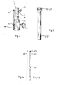
- Figures 1 a to c show a device to show 34 7 for temporarily shutting off a gas line to the gas line 7 is a Schleusenanord e voltage 10 mounted, wherein (not shown) by a known 3icherheits sluice drill 3 ine with the lock assembly 10 lockable mounting hole 40 in the gas line 7 was produced.
- the lock arrangement 10 is placed on the gas line 7 in a gas-tight and mechanically fixed manner with clamping means 33 with the interposition of an elastic seal.
- the device 34 the complete bladder setting device, is gas-tightly connected to the 3-lock arrangement 10.
- the lower part has a closure tube 18 into which an insertion head 41 is inserted.
- a downpipe 1 is sealed onto the closure tube 18. placed that branches into two guide tubes 2, 2 '. Below the branching area 3, the lower part 1 'of the downpipe and the part of the closure tube 18 adjoining it have essentially the same inside, clear width. For example, the following should be mentioned: clear width of the guide tubes 2, 2 ': 40 mm; Clear width of the downpipe erschClosing tube: 50 mm.
- a dividing wall 5 is provided from the branching area 3 down to the insertion head and forms an essential part of the invention.
- the partition 5 lies exactly in the middle according to FIG. 1a, so that the inside width of the downpipe connection pipe is exactly divided into two halves.
- the guide surfaces 4, 4 'located on the two sides of the partition 5 are coated or polished so that the folded bladder can slide easily along them. The same applies to the remaining walls of the clear width.
- the axes y and y 'of the two guide tubes form with the axis x -x of the gas conduit a plane to which the guide surfaces 4, 4' of the partition 5 are transverse, i. H. take an angle of 90 ° almost exactly.
- a deflection piece 11 is firmly inserted.
- the deflection piece 11 in turn has a first joint arrangement 13, to which a movable intermediate member 12 with a further joint 14 is connected.
- the intermediate link and the two joints 13, 14 make it possible for the partition 5, which is made of flexible metal, to strike once to the left and once to the right when the bladder bumps from one side or the other.
- the partition 5 is somewhat narrower than the diameter of the clear width below the branching area 3, so that the partition 5 can still fulfill its partitioning function sufficiently without having to remain exactly in the middle.
- the closure tube 18 or the clear width is accordingly divided into two chambers, which can be enlarged or reduced depending on the position of the partition 5.
- the partition 5 is formed in the first embodiment as a flat, metallic tongue 15 with a smooth surface. It is possible to insert the upper end of this "tongue" into a sliding gap 42, which is located in the apex of the deflection area 3. However, it is also possible to simply let this end swing freely. Due to the somewhat narrower conditions in the branching area, the deflection of the partition 5 in the branching area is more limited. It is thereby ruled out that the partition 5 swings over there to one side or the other so far that displacement when the bladder is pushed in is no longer guaranteed.
- the deflection piece 11 has two oppositely conductive deflection surfaces 9, 9 '. Since the partition 5 is always firmly connected to the deflection piece via the joint arrangement 12, 13, 14, the inserted bladder is always pushed exactly onto the respective deflection surface 9 or 9 ', which is decisive for its end position.
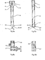
- Figures 7 a and 7 b show another embodiment of the partition.
- a correspondingly shaped plastic belt 5 'can also be used, which is suspended at its lower end at 43 and at its upper end at 42, but is designed on its remaining length in such a way that it dodges or bulge when in contact with the compressed shut-off bladder. Its extreme positions possible to the right and left can be derived from FIGS. 7 a and 7 b. To do this, it requires a certain excess length, width and flexibility, which depend on the nominal diameter and the length between the deflection area and the insertion head.
- the branching area 3 of the downpipe 1 is formed with two pipe branches 16, 16 ′ which run with a slight curvature against one another and which open via a common penetration area 17 into a sealing pipe 18 penetrated by the partition wall.
- the free end 24 of the closure tube 18 has saddle-shaped recesses 25, 25 'in a plane transverse to the axis x-x of the gas line.
- the recesses 25, 25 'leave lateral wall parts 36, 36' which cooperate with the deflecting piece 11 having the curved surface parts 9, 9 ', which is in the installed state between the wall surfaces 36, 36' and is fastened there Prevent the folded bladder from moving sideways into the gas line from the intended direction.
- the wall surface parts 36, 36 'thus act as additional guide aids when introducing the barrier bubbles.
- the lock arrangement 10 has an axially insertable closure tube 18 mende, with elastic sealing elements on the closure tube 18 gas-tight guide bush 26 and a gate valve 27. Furthermore, for the axial locking of the standpipe 18 in the guide bush 26 of the lock arrangement 10, a mounting hole 29, 30 having a pull rod 28 is arranged and fastened on the one hand to the downpipe 1 and, on the other hand, as attachment pins 31, 32. In addition, a lockable connector 38 is attached to the lock assembly 10, through which any gas leakage that may occur can be safely discharged.
- the two guide tubes 2, 2 ' accordinging to FIG. 1 have an arrangement, these converge at an acute angle a.
- This angle ⁇ can be between 2 ° and 5 °, preferably approximately 3 °.
- a shut-off device 19, 19 ' is arranged between the downpipe 1 and the guide tubes 2, 2'.
- the guide tubes 2, 2 '(FIG. 3) are designed to attach a closure cap 23 with an external thread that seals a bubble setting rod 22, 22' (FIG. 1).
- a control connection which can be closed with a towing element 21 and which is also provided for introducing inert gas.
- the device 34 is inserted with the closure tube 18 into the guide bush 26 and first used axially telescoping up to the gate valve 27.
- the shut-off valve 27 is opened and the sealing tube 18 is pushed in so far that its free end 24 with the wall parts 36, 36' below the axis xx of the gas line 7 protrudes into this.
- the device is locked in the lock arrangement 10 by attaching the pull rod 28 with the predetermined bores 29, 30 by plugging onto the fastening elements 31, 32.
- the articulated end of the partition 5 with the oppositely curved deflection surfaces 9, 9 'of the deflection piece 11 is in the position shown in FIG. 1 a below the axis xx of the gas line 7.
- the upper end of the partition 5 is either in a Sliding gap 42 is held displaceably or is loosely inserted into the branching area 3.
- shut-off elements 19, 19 ' When the shut-off elements 19, 19 'are closed, a closure cap 23' with a bladder setting rod (not shown) sealingly guided therein is then screwed onto one of the guide tubes, for example onto the right guide tube 2 '.
- a bladder setting rod (not shown) sealingly guided therein is then screwed onto one of the guide tubes, for example onto the right guide tube 2 '.
- the shut-off element 19 ' is opened and the guide tube and the base 37 are advanced by pushing down the bladder setting rod.
- the partition 5 is pressed to the left so that a relatively large space is available for the bladder. This state is shown in Figure 1 b.
- the bladder is then advanced into the right part 7 'of the gas line 7, sliding along the deflection surfaces and reaching the dashed position. If the bladder 37 'is pushed in, it is inflated and forms a first shutoff of the gas line 7. A bladder 37 is then similarly pushed into the left part of the gas line 7. The partition 5 then moves to the right and in turn allows the greater part of the clear width to be used. This state is shown in Figure 1 a.
- the bladder 37 is positioned in the left part of the gas line. After inflating, there are two shut-off bladders 37, 37 'to the right and left of the insertion head 1.
- the folded bladder for example in the event of a burst, can easily be pulled off again. Between the two shut-off bubbles and the sealing caps 23, 23 'there is a closed space which can be monitored via the control connection 21.
Landscapes
- Engineering & Computer Science (AREA)
- General Engineering & Computer Science (AREA)
- Mechanical Engineering (AREA)
- Pipe Accessories (AREA)
- Supply Devices, Intensifiers, Converters, And Telemotors (AREA)
- Chairs Characterized By Structure (AREA)
Abstract
Description
- Die Erfindung betrifft eine Vorrichtung zum provisorischen Absperren einer Gasleitung, die über eine Montagebohrung zugänglich gemacht worden ist, unter Verwendung von aufblasbaren Absperrblasen, die durch die Vorrichtung und die Montagebohrung in Leitungslängsrichtung (Achse x -x) zusammengedrückt einschiebbar sind, mit einem auf die Montagebohrung aufsetzbaren Verschlußrohr und einem in das Verschlußrohr eingesetzten Einführkopf mit einem Umlenkstück.
- Es ist bekannt, zum Anbohren von unter Druck stehenden Gasleitungen Schleusenanbohrgeräte zu verwenden, mit denen eine Montagebohrung von der Seite her in die Gasleitung einzubringen ist. Es ist weiterhin bekannt, die nach dem Einbringen einer Montagebohrung in das Gasrohr auf diesem gasdicht angebrachte Schleusen-und Verschlußanordnung in Verbindung mit einem Blasensetzgerät zu verwenden, mit dem eine schlaffe, zusammengedrückte Absperrblase in die Gasleitung einsetzbar ist. Zum eigentlichen Absperren wird dann die Blase durch ein Verbindungsrohr aufgeblasen. Bekannte Geräte (vgl. DE-A 27 12 952) sind mit Dicht-und Führungsmitteln so ausgebildet, daß elastische Absperrblasen in Gasleitungen ohne Gasaustritt gesetzt und wieder gezogen werden können. Bei noch nicht unterbrochener Gasströmung in der Gasleitung erfolgt der Einsatz der Absperrblase in Richtung stromaufwärts der Montagebohrung.
- Aus Sicherheitsgründen wird jedoch gefordert, daß jeweils ein Paar derartiger Absperrblasen für eine einzige Absperrlinie gesetzt wird, so daß für jeden abzusperrenden Rohrabschnitt 2 x 2 = 4 Blasen erforderlich sind (vgl. Neue DELIWA-Z.; 1973; S. 240 ff.). Mit dem bekannten Gerät kann jeweils nur eine Blase eingesetzt werden, so daß insgesamt viermal in die Gasleitung gebohrt werden muß. Dies bedingt einen relativ hohen Arbeits-und Kostenaufwand, ganz abgesehen von einem zusätzlichen Sicherheitsrisiko.
- Der Erfindung liegt die Aufgabe zugrunde, eine gegenüber dem Stand der Technik verbesserte Vorrichtung zum provisorischen Absperren einer Gasleitung anzugeben, mit der die Arbeitszeit insgesamt wesentlich verringert werden kann, ohne daß Abstriche an der Sicherheit gemacht werden müssen. Die verbesserte Vorrichtung soll mit bekannten Sicherheitsschleusen-Anbohrgeräten gasdicht zu verbinden sein und es wie bei den bekannten Geräten ermöglichen, daß während des Einsatzes jede der gesetzten Blasen unabhängig voneinander. bei einer Beschädigung wieder herausgezogen werden kann.
- Die Lösung der gestellten Aufgabe gelingt gemäß Erfindung mit einer Vorrichtung der eingangs genannten Art, die dadurch gekennzeichnet ist,
- -daß auf das Verschlußrohr ein sich in zwei Führungsrohre verzweigendes Rohr, vorzugsweise ein Hosenrohr aufgesetzt ist,
- -daß eine Trennwand mit gegenüberliegend angeordneten Führungsflächen vorgesehen ist, die vom Verzweigungsbereich des Rohres bis zum Umlenkstück reicht und die den unteren Teil des Rohres und das Verschlußrohr in zwei für eine zusammengedrückte Absperrblase durchgängige gängige Hälften teilt,
- -wobei die Achsen der beiden Führungsrohre mit der Achse des Gasleitungsrohres eine Ebene aufspannen, zu der die Führungsflächen der Trennwand quer stehen.
- Mit Vorteil ermöglicht es die erfindungsgemäße Vorrichtung, daß jeweils stromabwärts und stromaufwärts -von der Montagebohrung aus gesehen -eine Absperrblase zu setzen ist. Die Zahl der Bohrungen wird demnach im Vergleich zum Stand der Technik halbiert. Eine eventuell zerplatzte Absperrblase kann getrennt von der anderen ausgetauscht werden.
- Eine vorteilhafte Ausgestaltung sieht vor, daß die Trennwand als flache, vorzugsweise biegsame Zunge ausgebildet ist, deren Breite kleiner ist als der Durchmesser des Verschlußrohres, so daß die Zunge innerhalb des Rohres hin und her bewegt werden kann, und die weiterhin mit dem Umlenkstück über eine Gelenkanordnung verbunden ist. In einer anderen Ausführungsform ist es möglich, die Trennwand als biegsamen Riemen zu gestalten, der an seinen oberen und unteren Enden gehalten ist und eine ein Ausweichen oder Ausbeulen bei Kontakt mit der zusammengedrückten Absperrblase erlaubenden Flexibilität und Überlänge hat.
- Es werden durch die Anordnungen einer beweglichen Trennwand zwei nebeneinanderliegende, variable Räume geschaffen. Die bewegliche Trennwand ermöglicht es, daß jeweils der mit der zusammengefalteten Absperrblase zu beschickende Teil größer ist als der bereits mit einer Blase versehene oder noch zu beschickende Teil. Die Trennwand in ihrer Gestaltung als biegsame Zunge oder Riemen bildet demnach ein ausweichendes Führungsorgan, das je nach Bedarf von der zusammengefalteten Blase während des Einschiebevorganges aus der Mittellage herausgedrückt wird, so daß wesentlich größere Blasen damit gesetzt werden können, als es genau der Hälfte des Querschnittes des Verschlußrohres entspräche. Hierdurch eignet sich das Gerät insbesondere bei der Verwendung größerer Durchmesser, während es mit einer starren, in der Mitte angeordneten Trennwand sich nur für relativ kleine, einschiebbare Blasen eignete.
- Die Ausbildung der Trennwand als Führungsorgan mit Ausweichmöglichkeit erlaubt es, daß zunächst vom Montagebohrloch aus in der einen Richtung, beispielsweise nach rechts, eine zusammengefaltete Blase eingeschoben und dann zur Gasabsperrung aufgebläht wird, wobei der Zugangsschlauch in der entsprechenden Hälfte des Verschlußrohres verbleibt. Anschließend wird in die andere Hälfte des Verschlußrohres eine zusammengefaltete Blase eingeschoben und zu der vorgenannten in Gegenrichtung plaziert. Hierbei wirkt die elastische Trennwand als Führungsfläche und Trennung, indem sie jeweils bei Einführung einer Blase in die eine Richtung in entgegengesetzter Richtung "pendelnd" eine Ausweichbewegung ausführt, wodurch genügend Platz zur Umlenkung von Blasen und Anschlußrohr entstehen, um jeweils nach rechts und zum anderen nach links eine Blase einschieben zu können. Hierdurch können bei gleicher Montagebohrung größere Nennweiten aufgenommen werden als für den Fall, daß eine einfach durch Addition vergrößerte Bohrung eingebracht würde.
- Mit Vorteil wird die Wirkung der Trennwand dadurch begünstigt, daß das Endstück als Umlenkstück mit zwei entgegengesetzt liegenden Umlaufflächen gestaltet ist.
- Mit dem Einsetzen von zwei Blasen zu beiden Seiten einer Montagebohrung und darübergesetztem Verschlußrohr ergibt sich der Vorteil, daß zwischen den Blasen ein toter, abgesperrter Raum geschaffen wird. Das in diesen Raum enventuell eintretende Leckgas kann über den hierfür ausgestatteten Anschlußstutzen gefahrlos abgeleitet werden. Ein weiterer Anschluß ermöglicht es gegebenenfalls, daß ein Inertgas, beispielsweise Stickstoff, Kohlendioxid oder Argon, in den Bereich eingedrückt wird.
- Mit Vorteil ist eine unkomplizierte Ausgestaltung und Fertigungsmöglichkeit der Vorrichtung nach der Erfindung dadurch gegeben, daß der Verzweigungsbereich des Hosenrohres mit zwei mit geringer Krümmung gegeneinander verlaufenden Rohrzweigen ausgebildet ist, die über einen gemeinsammen Durchdringungsbereich in ein vom Führungsorgan durchsetztes Standrohr einmünden.
- Weiter ist das Verschlußrohr vorteilhaft so ausgebildet, daß sein freies Ende in der Projektion einer zur Achse der Gasleitung quer stehenden Ebene sattelförmige Ausnehmungen aufweist. Die hierbei seitlich stehenbleibenden Wandflächenteile des Verschiußrohres, die bis weit in die Gasleitung hineinragen, wirken beim Einführen einer Blase als seitliche Leitfläche, die ein Ausweichen der eingeführten Blase in einer Richtung quer zu den Umlenkflächen verhindert.
- Weitere zweckmäßige Ausgestaltungen der Vorrichtung sind entsprechend den Merkmalen weiterer Unteransprüche vorgesehen.
- Die Erfindung wird in der Zeichnung in zwei Ausführungsformen dargestellt und erläutert. Es zeigen:
- Figur 1 a eine auf eine Gasleitung mittels einer Schleusenanordnung aufgesetzte Vorrichtung, in Seitenansicht, mit der Trennwand in Mittelstellung;
- Figur 1 b die Vorrichtung gemäß Figur 1 a mit der Trennwand in linker Stellung;
- Figur 1 c die Vorrichtung gemäß Figur 1 a mit der Trennwand in rechter Stellung;
- Figur 2 eine Teilansicht der Vorrichtung aus einer gegenüber Figur 1 um 90° versetzten Betrachtungsebene;
- Figur 3 ein Führungsrohr in Ansicht;
- Figuren 4 a, 4 b eine Zugstange in Seitenansicht und in Frontansicht;
- Figuren 5 a, 5 b ein Hosenrohr in Seitenansicht und Frontansicht;
- Figuren 6 a, 6 b eine Trennwand in erster Ausführungsform in Seitenansicht und in Frontansicht;
- Figuren 7 a, 7 b eine Trennwand in zweiter Ausführungsform;
- Figuren 8 a, 8 b eine Schleusenanordnung in Seitenansicht und Frontansicht, teilweise im Schnitt.
- Die Figuren 1 a bis c zeigen eine Vorrichtung 34 zum provisorischen Absperren einer Gasleitung 7. Auf die Gasleitung 7 ist eine Schleusenanorde nung 10 aufgesetzt, wobei durch ein bekanntes 3icherheits-Schleusenbohrgerät (nicht dargestellt) 3ine mit der Schleusenanordnung 10 verschließbare Montagebohrung 40 in der Gasleitung 7 hergestellt wurde. Die Schleusenanordnung 10 ist nit Aufspannmitteln 33 unter Zwischenlage einer elastischen Dichtung gasdicht und mechanisch fest auf die Gasleitung 7 aufgesetzt. Die Vorrichtung 34, i. h. das komplette Blasensetzgerät, ist mit der 3chleusenanordnung 10 gasdicht verbunden.
- Der untere Teil weist ein Verschlußrohr 18 auf, in das ein Einführkopf 41 eingesetzt ist. Auf das Verschlußrohr 18 ist abgedichtet ein Hosenrohr 1 ein-bzw. aufgesetzt, das sich in zwei Führungsrohre 2, 2' verzweigt. Unterhalb des Verzweigungsbereiches 3 weist der untere Teil 1' des Hosenrohres und der sich daran anschließende Teil des Verschlußrohres 18 im wesentlichen die gleiche innere, lichte Weite auf. Als Anhaltspunkt sei beispielsweise genannt: lichte Weite der Führungsrohre 2, 2': 40 mm; lichte Weite des HosenrohresΛIerschIußrohres: 50 mm.
- Vom Verzweigungsbereich 3 bis hinunter zum Einführkopf ist eine Trennwand 5 vorgesehen, die einen erfindungswesentlichen Teil bildet. Die Trennwand 5 liegt gemäß Figur 1a genau in der Mitte, so daß die lichte Weite von HosenrohrNerschlußrohr genau in zwei Hälften geteilt ist. Die sich auf den beiden Seiten der Trennwand 5 befindenden Führungsflächen 4, 4' sind so belegt oder so poliert, daß an ihnen die zusammengefaltete Blase leicht entlanggleiten kann. Ähnliches gilt für die übrigen Wände der lichten Weite. Die Achsen y bzw. y' der beiden Führungsrohre bilden mit der Achse x -x des Gasleitungsrohres eine Ebene, zu der die Führungsflächen 4, 4' der Trennwand 5 quer stehen, d. h. ziemlich exakt einen Winkel von 90° einnehmen.
- Im unteren Teil des Einführkopfes 41, dessen genaue Gestaltung aus den Figuren 5 a und 5 b hervorgeht, ist ein Umlenkstück 11 fest eingesetzt. Das Umlenkstück 11 wiederum besitzt eine erste Gelenkanordnung 13, an die sich ein bewegliches Zwischenglied 12 mit einem weiteren Gelenk 14 anschließt. Das Zwischenglied und die beiden Gelenke 13, 14 ermöglichen es, daß die aus biegsamem Metall bestehende Trennwand 5 einmal nach links und einmal nach rechts schlägt, wenn von der einen oder anderen Seite die Blase anstößt. Diese beiden Stellungen sind in den Figuren 1 b und 1 c dargestellt. Dabei ist die Trennwand 5 etwas - schmaler als der Durchmesser der lichten Weite unterhalb des Verzweigungsbereiches 3, so daß die Trennwand 5 ihre Trennfunktion noch ausreichend erfüllen kann, ohne genau in der Mitte verharren zu müssen. Das Verschlußrohr 18 bzw. die lichte Weite ist demnach in zwei Kammern geteilt, die je nach Stellung der Trennwand 5 vergrößert oder verkleinert werden können.
- Wie aus den Figuren 6 a und 6 b im Detail ersichtlich, ist die Trennwand 5 in erster Ausführungsform als flache, metallische Zunge 15 mit glatter Oberfläche gebildet. Dabei ist möglich, das obere Ende dieser "Zunge" in einen Gleitspalt 42 einzuführen, der sich im Scheitel des Umlenkbereiches 3 befindet. Es ist jedoch auch möglich, dieses Ende einfach lose pendeln zu lassen. Durch die etwas beengteren Verhältnisse im Verzweigungsbereich ist der Ausschlag der Trennwand 5 im Verzweigungsbereich stärker begrenzt. Es wird dadurch ausgeschlossen, daß die Trennwand 5 dort soweit zur einen oder anderen Seite hinüber pendelt, daß ein Verschieben bei Einschieben der Blase nicht mehr gewährleistet ist.
- Das Umlenkstück 11 besitzt zwei entgegengesetzt leitende Umlenkflächen 9, 9'. Da die Trennwand 5 über die Gelenkanordnung 12, 13, 14 immer fest mit dem Umlenkstück verbunden ist, wird die eingeschobene Blase immer genau auf die jeweilige Umlenkfläche 9 bzw. 9' geschoben, die für ihre Endlage maßgebend ist.
- Figuren 7 a und 7 b zeigen eine andere Ausführungsform der Trennwand. Anstelle einer metallischen, nicht übermäßig flexiblen Metallzunge, kann auch ein entsprechend geformter Kunststoffriemen 5' verwendet werden, der an seinem unteren Ende bei 43 und an seinem oberen Ende bei 42 stationär aufgehängt ist, auf seiner übrigen Länge aber so gestaltet ist, daß er ausweichen oder ausbeulen kann bei Kon-takt mit der zusammengedrückten Absperrblase. Seine nach rechts und links möglichen Extremstellungen sind aus den Figuren 7 a und 7 b ableitbar. Er benötigt dazu eine gewisse Überlänge, Breite und Flexibilität, die sich nach der Nennweite und nach der Länge zwischen Umlenkbereich und Einführungskopf richten.
- Aus den Figuren 5 a und 5 b ist ersichtlich, daß der Verzweigungsbereich 3 des Hosenrohres 1 mit zwei mit geringer Krümmung gegeneinander verlaufenden Rohrzweigen 16, 16' ausgebildet ist, die über einen gemeinsamen Durchdringungsbereich 17 in ein von der Trennwand durchsetztes Verschlußrohr 18 einmünden. Das freie Ende 24 des Verschlußrohres 18 weist in einer zur Achse x-x der Gasleitung querstehenden Ebene sattelförmige Ausnehmungen 25, 25' auf. Die Ausnehmungen 25, 25' lassen seitliche Wandteile 36, 36' stehen, weiche im Zusammenwirken mit dem die gekrümmten Flächenteile 9, 9' aufweisenden Umlenkstück 11, das sich im eingebauten Zustand zwischen den Wandflächen 36, 36' befindet und dort befestigt ist, ein seitliches Ausweichen der zusammengefalteten Sperrblase aus der vorgesehenen Richtung in die Gasleitung verhindern. Die Wandflächenteile 36, 36' wirken somit als zusätzliche Führungshilfen bei der Einführung der Sperrblasen.
- Wie aus der Zusammenschau der Figuren 1 und 2, sowie insbesondere der Figuren 8 a und 8 b ersichtlich, weist die Schleusenanordnung 10 eine das Verschlußrohr 18 axial einschiebbar aufnehmende, mit elastischen Dichtungselementen am Verschlußrohr 18 gasdicht abschließende Führungsbuchse 26 sowie einen Absperrschieber 27 auf. Ferner ist zur axialen Arretierung des Standrohres 18 in der Führungsbuchse 26 der Schleusenanordnung 10 eine Montagebohrung 29, 30 aufweisende Zugstange 28 angeordnet und mit einerseits am Hosenrohr 1 und andererseits als Aufsteckdorne ausgebildeten Befestigungselementen 31, 32 befestigt. Außerdem ist an die Schleusenanordnung 10 ein verschließbarer Stutzen 38 angebracht, über den eventuell auftretende Gasleckmengen gefahrlos abgeleitet werden können.
- Weiter weisen die beiden Führungsrohre 2, 2' gemäß Figur 1 eine Anordnung auf, wobei diese im spitzen Winkel a gegeneinander zulaufen. Dieser Winkel α kann zwischen 2° und 5°, vorzugsweise ca. 3° betragen. Weiter ist zwischen dem Hosenrohr 1 und den Führungsrohren 2, 2' jeweils ein Absperrorgan 19, 19' angeordnet. Weiter sind die Führungsrohre 2, 2' (Fig. 3) zum Ansetzen einer eine Blasensetzstange 22, 22' (Fig. 1) abdichtend führenden Verschlußkappe 23 mit Außengewinde ausgebildet. Im Bereich des Hosenrohres 1 ist ein mit einem Abschlepporgan 21 verschließbarer Kontrollanschluß angeordnet, der auch zum Einführen von Inertgas vorgesehen ist.
- Die Arbeitsweise des Gerätes, wie sie sich aus den dargestellten Ausführungsbeispielen ergibt, sei erläutert:
- Nach Aufsetzen eines bekannten Sicherheits-Schleusenanbohrgerätes auf die Gasleitung 7 und Herstellung einer Montagebohrung 40 mit einem Durchmesser, der etwas größer ist als der Außendurchmesser des Verschlußrohres, wird nach Entfernen einer Bohrstange und deren Führung in der Schleusenanordnung 10 der Absperrschieber 27 in Verschlußstellung gebracht und damit die Montagestelle gegen Gasaustritt hermetisch gesichert.
- Sodann wird die Vorrichtung 34 mit dem Verschlußrohr 18 in die Führungsbuchse 26 eingeführt und zunächst bis zum Absperrschieber 27 axial teleskopierend eingesetzt. Nachdem man sich überzeugt hat, daß die Absperrorgane 19, 19' der Vorrichtung 34 geschlossen sind, wird der Absperrschieber 27 geöffnet und das Verschlußrohr 18 so weit eingeschoben, daß dessen freies Ende 24 mit den Wandteilen 36, 36' unterhalb der Achse x-x der Gasleitung 7 in diese hineinragt. Durch Anbringen der Zugstange 28 mit den vorgegebenen Bohrungen 29, 30 durch Aufstecken auf die Befestigungselemente 31, 32 wird die Vorrichtung in der Schleusenanordnung 10 arretiert. In dieser Stellung befindet sich das gelenkig befestigte Ende der Trennwand 5 mit den entgegengesetzt gekrümmten Umlenkflächen 9, 9' des Umlenkstückes 11 in der in Figur 1 a gezeichneten Position unterhalb der Achse x-x der Gasleitung 7. Das obere Ende der Trennwand 5 wird entweder in einem Gleitspalt 42 verschieblich gehalten oder ist lose in den Verzweigungsbereich 3 eingeschoben.
- Bei geschlossenen Absperrorganen 19, 19' wird sodann auf eines der Führungsrohre, beispielsweise auf das rechte Führungsrohr 2', eine Verschlußkappe 23' mit einer darin dichtend geführten Blasensetzstange (nicht dargestellt) aufgeschraubt. In den Raum des Führungsrohres 2' zwischen dem noch geschlossenen Absperrorgan 19' und der Kappe 23' befindet sich nunmehr das Ende einer Blasensetzstange mit einem Einführschlauch und am Ende einer zusammengefalteten Absperrblase 37'. Nunmehr wird das Absperrorgan 19' geöffnet und durch Herabstoßen der Blasensetzstange der Führungsschlauch und die Basis 37 vorgeschoben. Dabei wird die Trennwand 5 nach links gedrückt, so daß ein relativ großer Raum für die Blase zur Verfügung steht. Dieser Zustand ist in Figur 1 b dargestellt. Die Blase wird sodann in den rechten Teil 7' der Gasleitung 7 vorgeschoben, wobei sie entlang den Umlenkflächen gleitet und die gestrichelte Stellung erreicht. Ist die Blase 37' eingeschoben, wird sie aufgeblasen und bildet eine erste Absperrung der Gasleitung 7. Danach wird in ähnlicher Weise eine Blase 37 in den linken Teil der Gasleitung 7 eingeschoben. Die Trennwand 5 bewegt sich dann nach rechts und erlaubt es wiederum, den größeren Teil der lichten Weite auszunutzen. Dieser Zustand ist in Figur 1 a dargestellt. Die Blase 37 wird im linken Teil der Gasleitung positioniert. Nach dem Aufblasen befinden sich zwei Absperrblasen 37, 37' rechts und links vom Einführungskopf 1. Die zusammengefaltete Blase, beispielsweise bei einem Platzen, kann ohne weiteres wieder abgezogen werden. Zwischen den beiden Absperrblasen und den abdichtenden Verschlußkappen 23, 23' befindet sich ein abgeschlossener Raum, der über den Kontrollanschluß 21 überwacht werden kann.
Claims (8)
Priority Applications (1)
| Application Number | Priority Date | Filing Date | Title |
|---|---|---|---|
| AT86102779T ATE45619T1 (de) | 1985-03-11 | 1986-03-03 | Vorrichtung zum provisorischen absperren einer gasleitung mittels absperrblasen. |
Applications Claiming Priority (2)
| Application Number | Priority Date | Filing Date | Title |
|---|---|---|---|
| DE3508591A DE3508591C2 (de) | 1985-03-11 | 1985-03-11 | Vorrichtung zum Setzen von aufblasbaren Absperrblasen in Gasleitungen über eine Montagebohrung |
| DE3508591 | 1985-03-11 |
Publications (2)
| Publication Number | Publication Date |
|---|---|
| EP0197295A1 true EP0197295A1 (de) | 1986-10-15 |
| EP0197295B1 EP0197295B1 (de) | 1989-08-16 |
Family
ID=6264819
Family Applications (1)
| Application Number | Title | Priority Date | Filing Date |
|---|---|---|---|
| EP86102779A Expired EP0197295B1 (de) | 1985-03-11 | 1986-03-03 | Vorrichtung zum provisorischen Absperren einer Gasleitung mittels Absperrblasen |
Country Status (3)
| Country | Link |
|---|---|
| EP (1) | EP0197295B1 (de) |
| AT (1) | ATE45619T1 (de) |
| DE (2) | DE3508591C2 (de) |
Cited By (2)
| Publication number | Priority date | Publication date | Assignee | Title |
|---|---|---|---|---|
| EP4350191A1 (de) | 2022-10-05 | 2024-04-10 | Westnetz GmbH | Blasensetzvorrichtung und verfahren zur verwendung einer blasensetzvorrichtung |
| DE102024101843A1 (de) * | 2024-01-23 | 2025-07-24 | Westnetz Gmbh | Verfahren zum kontrollierten Abführen eines abzuschirmenden Gases aus einem gasführenden Leitungsabschnitt |
Families Citing this family (3)
| Publication number | Priority date | Publication date | Assignee | Title |
|---|---|---|---|---|
| DE19530962C2 (de) * | 1995-08-23 | 1998-08-27 | Vew En Ag | Vorrichtung zum Setzen von aufblasbaren Absperrblasen in Rohrleitungen |
| DE102009019998B4 (de) | 2009-05-05 | 2013-03-28 | Swm Services Gmbh | Entgrater und Verfahren zum Entgraten von Bohrrändern in Gasleitungen |
| US8800601B2 (en) * | 2012-01-24 | 2014-08-12 | Operations Technology Development, Nfp | Insertion and removal of inflatable pipeline flow stopper bags |
Citations (3)
| Publication number | Priority date | Publication date | Assignee | Title |
|---|---|---|---|---|
| GB1311017A (en) * | 1970-12-16 | 1973-03-21 | Gas Council | Method and apparatus for blocking pressure pipes |
| DE2712952A1 (de) * | 1977-03-24 | 1978-09-28 | Versorgungs Unternehmen Avu Ag | Vorrichtung zum einfuehren von aufblasbaren absperrblasen in versorgungsleitungen |
| US4428204A (en) * | 1981-12-08 | 1984-01-31 | Brister Beryle D | Method for forming a temporary plug in a fluid conduit |
Family Cites Families (1)
| Publication number | Priority date | Publication date | Assignee | Title |
|---|---|---|---|---|
| US4155373A (en) * | 1976-12-06 | 1979-05-22 | Digiovanni Bernard A | Method for shutting off gas flow in plastic pipes |
-
1985
- 1985-03-11 DE DE3508591A patent/DE3508591C2/de not_active Expired
-
1986
- 1986-03-03 DE DE8686102779T patent/DE3665095D1/de not_active Expired
- 1986-03-03 EP EP86102779A patent/EP0197295B1/de not_active Expired
- 1986-03-03 AT AT86102779T patent/ATE45619T1/de not_active IP Right Cessation
Patent Citations (3)
| Publication number | Priority date | Publication date | Assignee | Title |
|---|---|---|---|---|
| GB1311017A (en) * | 1970-12-16 | 1973-03-21 | Gas Council | Method and apparatus for blocking pressure pipes |
| DE2712952A1 (de) * | 1977-03-24 | 1978-09-28 | Versorgungs Unternehmen Avu Ag | Vorrichtung zum einfuehren von aufblasbaren absperrblasen in versorgungsleitungen |
| US4428204A (en) * | 1981-12-08 | 1984-01-31 | Brister Beryle D | Method for forming a temporary plug in a fluid conduit |
Cited By (3)
| Publication number | Priority date | Publication date | Assignee | Title |
|---|---|---|---|---|
| EP4350191A1 (de) | 2022-10-05 | 2024-04-10 | Westnetz GmbH | Blasensetzvorrichtung und verfahren zur verwendung einer blasensetzvorrichtung |
| DE102022125589A1 (de) | 2022-10-05 | 2024-04-11 | Westnetz Gmbh | Blasensetzvorrichtung und Verfahren zur Verwendung einer Blasensetzvorrichtung |
| DE102024101843A1 (de) * | 2024-01-23 | 2025-07-24 | Westnetz Gmbh | Verfahren zum kontrollierten Abführen eines abzuschirmenden Gases aus einem gasführenden Leitungsabschnitt |
Also Published As
| Publication number | Publication date |
|---|---|
| EP0197295B1 (de) | 1989-08-16 |
| ATE45619T1 (de) | 1989-09-15 |
| DE3665095D1 (en) | 1989-09-21 |
| DE3508591C2 (de) | 1987-04-02 |
| DE3508591A1 (de) | 1986-09-18 |
Similar Documents
| Publication | Publication Date | Title |
|---|---|---|
| EP1222421B1 (de) | Rohrkupplung mit schnellverschluss | |
| DE2732048C2 (de) | Befestigungsvorrichtung zum Verbinden zweier Bauteile in vorbestimmten Orientierungen | |
| DE4016090A1 (de) | Rohrverbinder-lastelement | |
| EP2047110B1 (de) | Fluidtechnische vorrichtung | |
| DE3145284C2 (de) | ||
| EP2147191A2 (de) | Hydraulikstempel mit rechteckigen sicherungsdrähten | |
| EP0862002A1 (de) | Verbindungseinrichtung für zwei Körper einer fluiddurchströmten Baugruppe | |
| DE69124098T2 (de) | Einstellbare kontaminationshülse für katheter | |
| DE3014834C2 (de) | Bohrlochverschlußstopfen | |
| EP0197295B1 (de) | Vorrichtung zum provisorischen Absperren einer Gasleitung mittels Absperrblasen | |
| DE9102781U1 (de) | Zum Leiten bzw. Kanalisieren und Verteilen von Fluiden im allgemeinen dienende hohle Schiene bzw. Stange | |
| DE2159518A1 (de) | Verfahren und vorrichtung zum absperren eines unter druck stehenden rohres, insbes. in gasrohrnetzen | |
| DE2411362B2 (de) | Verschlussvorrichtung, bestehend aus einem drehzylinderschloss und dazugehoerigem flachschluessel | |
| DE3726258C2 (de) | Vorrichtung zum Absperren von rohrförmigen Transportleitungen für Flüssigkeit oder Gas | |
| DE19812319B4 (de) | Druckausgleichseinrichtung | |
| DE3728577C2 (de) | ||
| DE20105511U1 (de) | Seitengassackmodul | |
| DE3729311C2 (de) | Vorrichtung zum Absperren von Gasleitungen | |
| DE102012105399A1 (de) | Rohrverbindung | |
| DE2937702A1 (de) | Klappenanordnung an der einfahrkontaktdurchfuehrungsoeffnung in der schottwand einer hochspannungsschaltzelle | |
| AT222600B (de) | Rohrverbindung | |
| DE3345430C2 (de) | ||
| DE8132177U1 (de) | "absperrblase bei gasleitungen" | |
| AT408003B (de) | Einrichtung zur abdichtung der sich zwischen zwei betonkörpern ausbildenden fuge | |
| DE4311629C1 (de) | Verschluß zum Verschließen eines Medienkanals eines Druckleitungssystems für ein unter Druck stehendes Medium, insbesondere zum Verschließen eines Medienkanals eines Leitungssystems für die Trinkwasserversorgung |
Legal Events
| Date | Code | Title | Description |
|---|---|---|---|
| PUAI | Public reference made under article 153(3) epc to a published international application that has entered the european phase |
Free format text: ORIGINAL CODE: 0009012 |
|
| AK | Designated contracting states |
Kind code of ref document: A1 Designated state(s): AT BE CH DE FR GB IT LI LU NL SE |
|
| 17P | Request for examination filed |
Effective date: 19870319 |
|
| 17Q | First examination report despatched |
Effective date: 19881121 |
|
| GRAA | (expected) grant |
Free format text: ORIGINAL CODE: 0009210 |
|
| AK | Designated contracting states |
Kind code of ref document: B1 Designated state(s): AT BE CH DE FR GB IT LI LU NL SE |
|
| REF | Corresponds to: |
Ref document number: 45619 Country of ref document: AT Date of ref document: 19890915 Kind code of ref document: T |
|
| GBT | Gb: translation of ep patent filed (gb section 77(6)(a)/1977) | ||
| REF | Corresponds to: |
Ref document number: 3665095 Country of ref document: DE Date of ref document: 19890921 |
|
| ITF | It: translation for a ep patent filed | ||
| ET | Fr: translation filed | ||
| PLBE | No opposition filed within time limit |
Free format text: ORIGINAL CODE: 0009261 |
|
| STAA | Information on the status of an ep patent application or granted ep patent |
Free format text: STATUS: NO OPPOSITION FILED WITHIN TIME LIMIT |
|
| 26N | No opposition filed | ||
| ITTA | It: last paid annual fee | ||
| EPTA | Lu: last paid annual fee | ||
| EAL | Se: european patent in force in sweden |
Ref document number: 86102779.5 |
|
| PGFP | Annual fee paid to national office [announced via postgrant information from national office to epo] |
Ref country code: GB Payment date: 19960220 Year of fee payment: 11 |
|
| PGFP | Annual fee paid to national office [announced via postgrant information from national office to epo] |
Ref country code: SE Payment date: 19960223 Year of fee payment: 11 |
|
| PGFP | Annual fee paid to national office [announced via postgrant information from national office to epo] |
Ref country code: LU Payment date: 19960301 Year of fee payment: 11 |
|
| PG25 | Lapsed in a contracting state [announced via postgrant information from national office to epo] |
Ref country code: LU Free format text: LAPSE BECAUSE OF NON-PAYMENT OF DUE FEES Effective date: 19970303 Ref country code: GB Effective date: 19970303 |
|
| PG25 | Lapsed in a contracting state [announced via postgrant information from national office to epo] |
Ref country code: SE Effective date: 19970304 |
|
| GBPC | Gb: european patent ceased through non-payment of renewal fee |
Effective date: 19970303 |
|
| EUG | Se: european patent has lapsed |
Ref document number: 86102779.5 |
|
| PGFP | Annual fee paid to national office [announced via postgrant information from national office to epo] |
Ref country code: NL Payment date: 20030318 Year of fee payment: 18 Ref country code: CH Payment date: 20030318 Year of fee payment: 18 |
|
| PGFP | Annual fee paid to national office [announced via postgrant information from national office to epo] |
Ref country code: FR Payment date: 20030319 Year of fee payment: 18 |
|
| PGFP | Annual fee paid to national office [announced via postgrant information from national office to epo] |
Ref country code: AT Payment date: 20030320 Year of fee payment: 18 |
|
| PGFP | Annual fee paid to national office [announced via postgrant information from national office to epo] |
Ref country code: BE Payment date: 20030423 Year of fee payment: 18 |
|
| PG25 | Lapsed in a contracting state [announced via postgrant information from national office to epo] |
Ref country code: AT Free format text: LAPSE BECAUSE OF NON-PAYMENT OF DUE FEES Effective date: 20040303 |
|
| PG25 | Lapsed in a contracting state [announced via postgrant information from national office to epo] |
Ref country code: LI Free format text: LAPSE BECAUSE OF NON-PAYMENT OF DUE FEES Effective date: 20040331 Ref country code: CH Free format text: LAPSE BECAUSE OF NON-PAYMENT OF DUE FEES Effective date: 20040331 Ref country code: BE Free format text: LAPSE BECAUSE OF NON-PAYMENT OF DUE FEES Effective date: 20040331 |
|
| BERE | Be: lapsed |
Owner name: *VEREINIGTE ELEKTRIZITATSWERKE WESTFALEN A.G. Effective date: 20040331 |
|
| PG25 | Lapsed in a contracting state [announced via postgrant information from national office to epo] |
Ref country code: NL Free format text: LAPSE BECAUSE OF NON-PAYMENT OF DUE FEES Effective date: 20041001 |
|
| REG | Reference to a national code |
Ref country code: CH Ref legal event code: PL |
|
| PG25 | Lapsed in a contracting state [announced via postgrant information from national office to epo] |
Ref country code: FR Free format text: LAPSE BECAUSE OF NON-PAYMENT OF DUE FEES Effective date: 20041130 |
|
| NLV4 | Nl: lapsed or anulled due to non-payment of the annual fee |
Effective date: 20041001 |
|
| REG | Reference to a national code |
Ref country code: FR Ref legal event code: ST |
|
| PG25 | Lapsed in a contracting state [announced via postgrant information from national office to epo] |
Ref country code: IT Free format text: LAPSE BECAUSE OF NON-PAYMENT OF DUE FEES;WARNING: LAPSES OF ITALIAN PATENTS WITH EFFECTIVE DATE BEFORE 2007 MAY HAVE OCCURRED AT ANY TIME BEFORE 2007. THE CORRECT EFFECTIVE DATE MAY BE DIFFERENT FROM THE ONE RECORDED. Effective date: 20050303 |
|
| PGFP | Annual fee paid to national office [announced via postgrant information from national office to epo] |
Ref country code: DE Payment date: 20050304 Year of fee payment: 20 |