EP0197295B1 - Dispositif pour obturer provisoirement une conduite de gaz à l'aide de vessies gonflables - Google Patents
Dispositif pour obturer provisoirement une conduite de gaz à l'aide de vessies gonflables Download PDFInfo
- Publication number
- EP0197295B1 EP0197295B1 EP86102779A EP86102779A EP0197295B1 EP 0197295 B1 EP0197295 B1 EP 0197295B1 EP 86102779 A EP86102779 A EP 86102779A EP 86102779 A EP86102779 A EP 86102779A EP 0197295 B1 EP0197295 B1 EP 0197295B1
- Authority
- EP
- European Patent Office
- Prior art keywords
- pipe
- partition
- guide
- closing
- deflection
- Prior art date
- Legal status (The legal status is an assumption and is not a legal conclusion. Google has not performed a legal analysis and makes no representation as to the accuracy of the status listed.)
- Expired
Links
Images



Classifications
-
- F—MECHANICAL ENGINEERING; LIGHTING; HEATING; WEAPONS; BLASTING
- F16—ENGINEERING ELEMENTS AND UNITS; GENERAL MEASURES FOR PRODUCING AND MAINTAINING EFFECTIVE FUNCTIONING OF MACHINES OR INSTALLATIONS; THERMAL INSULATION IN GENERAL
- F16L—PIPES; JOINTS OR FITTINGS FOR PIPES; SUPPORTS FOR PIPES, CABLES OR PROTECTIVE TUBING; MEANS FOR THERMAL INSULATION IN GENERAL
- F16L55/00—Devices or appurtenances for use in, or in connection with, pipes or pipe systems
- F16L55/10—Means for stopping flow in pipes or hoses
- F16L55/12—Means for stopping flow in pipes or hoses by introducing into the pipe a member expandable in situ
- F16L55/124—Means for stopping flow in pipes or hoses by introducing into the pipe a member expandable in situ introduced radially into the pipe or hose
Definitions
- the invention relates to a device for provisionally shutting off a gas line, which has been made accessible via a mounting hole, using inflatable shut-off bubbles, which can be pushed together by the device and the mounting hole in the longitudinal direction of the line (axis x - x), with one onto the mounting hole attachable closure tube and an insertion head inserted into the closure tube with a deflection piece.
- lock tapping devices for tapping pressurized gas lines, with which a mounting hole can be drilled into the gas line from the side.
- lock and closure arrangement which has been gas-tightly attached to the gas pipe after the introduction of a mounting hole in the gas pipe, in connection with a bladder setting device with which a slack, compressed shut-off bladder can be inserted into the gas line. The bladder is then inflated through a connecting tube to actually shut it off.
- Known devices cf. DE-A 27 12 952 are designed with sealing and guiding means in such a way that elastic shut-off bubbles can be set in gas lines without gas leakage and can be pulled again. If the gas flow in the gas line has not yet been interrupted, the shut-off bladder is used in the direction upstream of the mounting hole.
- the known device only one bladder can be used at a time, so that a total of four bores have to be drilled in the gas line. This requires a relatively high amount of work and costs, quite apart from an additional security risk.
- the invention has for its object to provide an improved device compared to the prior art for temporarily shutting off a gas line, with which the total working time can be significantly reduced without sacrificing safety.
- the improved device is said to be gas-tight to be connected to known security lock tapping devices and, like the known devices, to make it possible for each of the bubbles set to be pulled out independently of one another in the event of damage during use.
- the device according to the invention advantageously enables a shut-off bladder to be placed downstream and upstream, as seen from the mounting hole.
- the number of holes is therefore halved compared to the prior art.
- a possibly burst shut-off bladder can be replaced separately from the other.
- the partition is designed as a flat, preferably flexible tongue, the width of which is smaller than the diameter of the sealing tube, so that the tongue can be moved back and forth within the tube, and which continues to be connected to the deflection piece via a Joint arrangement is connected.
- the partition it is possible to design the partition as a flexible strap which is held at its upper and lower ends and which has flexibility and excess length which allows it to deflect or bulge on contact with the compressed shut-off bladder.
- the arrangement of a movable partition wall creates two adjacent, variable rooms.
- the movable partition wall makes it possible that the part to be loaded with the folded shut-off bladder is larger than the part which has already been provided with a bladder or is still to be loaded.
- the partition in its design as a flexible tongue or strap accordingly forms an evasive guide element, which is pushed out of the folded bladder as required during the insertion process from the central position, so that much larger bladders can be set with it than exactly half the cross-section of the sealing tube. This makes the device particularly suitable for use with larger diameters, while with a rigid partition arranged in the middle it was only suitable for relatively small, insertable bubbles.
- the design of the partition as a guide element with a possibility of evasion allows a folded-in bladder to be inserted first from the mounting hole in one direction, for example to the right, and then inflated to shut off the gas, the access hose remaining in the corresponding half of the sealing tube. A folded bladder is then inserted into the other half of the sealing tube and placed in the opposite direction to the aforementioned.
- the elastic partition acts as a guide surface and door tion by performing an evasive movement "swinging" in the opposite direction each time a bubble is introduced, which creates enough space for deflecting bubbles and connecting pipe so that a bubble can be inserted to the right and the other to the left.
- larger nominal widths can be accommodated with the same mounting hole than in the event that a hole that was simply enlarged by addition would be introduced.
- the effect of the partition wall is advantageously favored in that the end piece is designed as a deflecting piece with two opposite circumferential surfaces.
- a further connection may make it possible for an inert gas, for example nitrogen, carbon dioxide or argon, to be pressed into the region.
- the branching area of the downpipe is formed with two pipe branches running with a slight curvature, which branch out into a standpipe penetrated by the guide member via a common penetration area.
- the closure tube is advantageously designed such that its free end has saddle-shaped recesses in the projection of a plane transverse to the axis of the gas line.
- the wall surface parts of the closure tube which remain to the side and protrude far into the gas line act when a bladder is inserted as a lateral guide surface which prevents the introduced bladder from escaping in a direction transverse to the deflection surfaces.
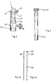
- FIGS. 1 a to c show a device 34 for provisionally shutting off a gas line 7.
- a lock arrangement 10 is placed on the gas line 7, a mounting hole 40 in the gas line 7 that can be closed with the lock arrangement 10 being closed by a known security lock drilling device (not shown) was produced.
- the lock arrangement 10 is placed on the gas line 7 in a gas-tight and mechanically fixed manner with clamping means 33 with the interposition of an elastic seal.
- the device 34 i. H. the complete bladder setting device is gas-tightly connected to the lock arrangement 10.
- the lower part has a closure tube 18 into which an insertion head 41 is inserted.
- the lower part 1 'of the downpipe and the part of the closure tube 18 adjoining it have essentially the same inside, clear width.
- clear width of the guide tubes 2, 2 ' 40 mm
- Clear width of the downpipe 50 mm.
- a dividing wall 5 is provided from the branching area 3 down to the insertion head and forms an essential part of the invention.
- the partition 5 lies according to Figure 1a exactly in the middle, so that the inside width of the downpipe connection pipe is exactly divided into two halves.
- the guide surfaces 4, 4 'located on the two sides of the partition 5 are coated or polished so that the folded bladder can easily slide along them. The same applies to the remaining walls of the clear width.
- the axes y and y 'of the two guide tubes form a plane with the axis x - x of the gas line tube, to which the guide surfaces 4, 4' of the partition 5 are transverse, that is to say they take an angle of 90 ° almost exactly.
- a deflection piece 11 is firmly inserted.
- the deflection piece 11 in turn has a first joint arrangement 13, to which a movable intermediate member 12 with a further joint 14 is connected.
- the intermediate link and the two joints 13, 14 make it possible for the partition 5, which is made of flexible metal, to strike once to the left and once to the right when the bladder bumps from one side or the other.
- the partition 5 is slightly narrower than the diameter of the clear width below the branching area 3, so that the partition 5 can still fulfill its separating function sufficiently without having to remain exactly in the middle.
- the closure tube 18 or the inside width is accordingly divided into two chambers, which can be enlarged or reduced depending on the position of the partition 5.
- the partition 5 is formed in the first embodiment as a flat, metallic tongue 15 with a smooth surface. It is possible to insert the upper end of this "tongue" into a sliding gap, which is located in the apex of the deflection area 3. However, it is also possible to simply let this end swing freely. Due to the somewhat narrower conditions in the branching area, the deflection of the partition 5 in the branching area is more limited. It is thereby ruled out that the partition 5 swings over there to one side or the other so far that displacement when the bladder is pushed in is no longer guaranteed.
- the deflection piece 11 has two oppositely conductive deflection surfaces 9, 9 '. Since the partition 5 via the hinge assembly 12; 13, 14 is always firmly connected to the deflection piece, the inserted bladder is always pushed exactly onto the respective deflection surface 9 or 9 ', which is decisive for its end position.
- Figures 7 a and 7 b show another embodiment of the partition.
- a correspondingly shaped plastic belt 5 'can also be used, which is suspended at its lower end at 43 and at its upper end at 42, but is designed on its remaining length in such a way that it dodges or bulge when in contact with the compressed shut-off bladder. Its extreme positions possible to the right and left can be derived from FIGS. 7 a and 7 b. To do this, it requires a certain excess length, width and flexibility, which depend on the nominal diameter and the length between the deflection area and the insertion head.
- the branching area 3 of the downpipe 1 is formed with two pipe branches 16, 16 ′ which run with a slight curvature against one another and which open via a common penetration area 17 into a sealing pipe 18 penetrated by the partition wall.
- the free end 24 of the closure tube 18 has saddle-shaped recesses 25, 25 'in a plane transverse to the axis x-x of the gas line.
- the recesses 25, 25 'leave lateral wall parts 36, 36' which in cooperation with the deflecting piece 11 having the curved surface parts 9, 9 ', which is located in the installed state between the wall surfaces 36, 36' and is fastened there Prevent the folded bladder from moving sideways into the gas line from the intended direction.
- the wall surface parts 36, 36 'thus act as additional guide aids when introducing the barrier bubbles.
- the lock arrangement 10 has a guide bush 26, which axially insertably locks the closure tube 18 and seals gas-tight with elastic sealing elements on the closure tube 18, and a gate valve 27. Furthermore, for the axial locking of the standpipe 18 in the guide bush 26 of the lock arrangement 10, a mounting hole 29, 30 having a pull rod 28 is arranged and fastened on the one hand to the downpipe 1 and, on the other hand, as attachment pins 31, 32. In addition, a lockable connector 38 is attached to the lock assembly 10, through which any gas leakage that may occur can be safely discharged.
- the two guide tubes 2, 2 'according to FIG. 1 have an arrangement, these converge at an acute angle a.
- This angle a can be between 2 ° and 5 ° , preferably approximately 3 ° .
- a shut-off device 19, 19 ' is arranged between the downpipe 1 and the guide tubes 2, 2'.
- the guide tubes 2, 2 '(FIG. 3) are designed to attach a closure cap 23 with an external thread, which seals a bubble setting rod 22, 22' (FIG. 1).
- a control connection which can be closed with a towing element 21 and which is also provided for introducing inert gas.
- the gate valve 27 After placing a known security lock tapping device on the gas line 7 and producing a mounting hole 40 with a diameter that is slightly larger than the outside diameter of the sealing tube, after removing a boring bar and guiding it in the lock arrangement 10, the gate valve 27 is brought into the closed position and thus the assembly point is hermetically secured against gas leakage.
- the device 34 is inserted with the closure tube 18 into the guide bush 26 and first used axially telescoping up to the gate valve 27.
- the shut-off valve 27 is opened and the sealing tube 18 is pushed in so far that its free end 24 with the wall parts 36, 36' below the axis xx of the gas line 7 protrudes into this.
- the device is locked in the lock arrangement 10 by attaching the pull rod 28 with the predetermined bores 29, 30 by plugging onto the fastening elements 31, 32.
- the articulated end of the partition 5 with the oppositely curved deflection surfaces 9, 9 'of the deflection piece 11 is in the position shown in FIG. 1 a below the axis xx of the gas line 7.
- the upper end of the partition 5 is either in a Sliding gap 42 is held displaceably or is loosely inserted into the branching area 3.
- shut-off elements 19, 19 ' When the shut-off elements 19, 19 'are closed, a closure cap 23' with a bladder setting rod (not shown) sealingly guided therein is then screwed onto one of the guide tubes, for example onto the right guide tube 2 '.
- a closure cap 23' with a bladder setting rod (not shown) sealingly guided therein is then screwed onto one of the guide tubes, for example onto the right guide tube 2 '.
- the still closed shut-off element 19' and the cap 23 ' In the space of the guide tube 2 'between the still closed shut-off element 19' and the cap 23 'is now the end of a bladder setting rod with an insertion tube and at the end of a folded shut-off bladder 37'.
- the shut-off element 19 ' is opened and the guide tube and the base 37 are advanced by pushing down the bladder setting rod.
- the partition 5 is pressed to the left so that a relatively large space is available for the bladder. This state is shown in Figure 1 b.
- the bladder is then advanced into the right part 7 'of the gas line 7, sliding along the deflection surfaces and reaching the dashed position. If the bladder 37 'is pushed in, it is inflated and forms a first shut-off of the gas line 7. A bladder 37 is then similarly pushed into the left part of the gas line 7. The partition 5 then moves to the right and in turn allows the greater part of the clear width to be used. This state is shown in Figure 1 a.
- the bladder 37 is positioned in the left part of the gas line. After inflating, there are two shut-off bladders 37, 37 'to the right and left of the insertion head 1.
- the folded bladder for example in the event of a burst, can easily be pulled off again. Between the two shut-off bubbles and the sealing caps 23, 23 'there is a closed space which can be monitored via the control connection 21.
Landscapes
- Engineering & Computer Science (AREA)
- General Engineering & Computer Science (AREA)
- Mechanical Engineering (AREA)
- Pipe Accessories (AREA)
- Supply Devices, Intensifiers, Converters, And Telemotors (AREA)
- Chairs Characterized By Structure (AREA)
Claims (7)
Priority Applications (1)
| Application Number | Priority Date | Filing Date | Title |
|---|---|---|---|
| AT86102779T ATE45619T1 (de) | 1985-03-11 | 1986-03-03 | Vorrichtung zum provisorischen absperren einer gasleitung mittels absperrblasen. |
Applications Claiming Priority (2)
| Application Number | Priority Date | Filing Date | Title |
|---|---|---|---|
| DE3508591A DE3508591C2 (de) | 1985-03-11 | 1985-03-11 | Vorrichtung zum Setzen von aufblasbaren Absperrblasen in Gasleitungen über eine Montagebohrung |
| DE3508591 | 1985-03-11 |
Publications (2)
| Publication Number | Publication Date |
|---|---|
| EP0197295A1 EP0197295A1 (fr) | 1986-10-15 |
| EP0197295B1 true EP0197295B1 (fr) | 1989-08-16 |
Family
ID=6264819
Family Applications (1)
| Application Number | Title | Priority Date | Filing Date |
|---|---|---|---|
| EP86102779A Expired EP0197295B1 (fr) | 1985-03-11 | 1986-03-03 | Dispositif pour obturer provisoirement une conduite de gaz à l'aide de vessies gonflables |
Country Status (3)
| Country | Link |
|---|---|
| EP (1) | EP0197295B1 (fr) |
| AT (1) | ATE45619T1 (fr) |
| DE (2) | DE3508591C2 (fr) |
Cited By (1)
| Publication number | Priority date | Publication date | Assignee | Title |
|---|---|---|---|---|
| EP4592584A1 (fr) * | 2024-01-23 | 2025-07-30 | Westnetz GmbH | Procédé pour l'évacuation contrôlée d'un gaz à protéger d'une section de conduite transportant du gaz |
Families Citing this family (4)
| Publication number | Priority date | Publication date | Assignee | Title |
|---|---|---|---|---|
| DE19530962C2 (de) * | 1995-08-23 | 1998-08-27 | Vew En Ag | Vorrichtung zum Setzen von aufblasbaren Absperrblasen in Rohrleitungen |
| DE102009019998B4 (de) | 2009-05-05 | 2013-03-28 | Swm Services Gmbh | Entgrater und Verfahren zum Entgraten von Bohrrändern in Gasleitungen |
| US8800601B2 (en) * | 2012-01-24 | 2014-08-12 | Operations Technology Development, Nfp | Insertion and removal of inflatable pipeline flow stopper bags |
| DE102022125589A1 (de) | 2022-10-05 | 2024-04-11 | Westnetz Gmbh | Blasensetzvorrichtung und Verfahren zur Verwendung einer Blasensetzvorrichtung |
Family Cites Families (4)
| Publication number | Priority date | Publication date | Assignee | Title |
|---|---|---|---|---|
| GB1311017A (en) * | 1970-12-16 | 1973-03-21 | Gas Council | Method and apparatus for blocking pressure pipes |
| US4155373A (en) * | 1976-12-06 | 1979-05-22 | Digiovanni Bernard A | Method for shutting off gas flow in plastic pipes |
| DE2712952A1 (de) * | 1977-03-24 | 1978-09-28 | Versorgungs Unternehmen Avu Ag | Vorrichtung zum einfuehren von aufblasbaren absperrblasen in versorgungsleitungen |
| US4428204A (en) * | 1981-12-08 | 1984-01-31 | Brister Beryle D | Method for forming a temporary plug in a fluid conduit |
-
1985
- 1985-03-11 DE DE3508591A patent/DE3508591C2/de not_active Expired
-
1986
- 1986-03-03 DE DE8686102779T patent/DE3665095D1/de not_active Expired
- 1986-03-03 AT AT86102779T patent/ATE45619T1/de not_active IP Right Cessation
- 1986-03-03 EP EP86102779A patent/EP0197295B1/fr not_active Expired
Cited By (1)
| Publication number | Priority date | Publication date | Assignee | Title |
|---|---|---|---|---|
| EP4592584A1 (fr) * | 2024-01-23 | 2025-07-30 | Westnetz GmbH | Procédé pour l'évacuation contrôlée d'un gaz à protéger d'une section de conduite transportant du gaz |
Also Published As
| Publication number | Publication date |
|---|---|
| DE3665095D1 (en) | 1989-09-21 |
| DE3508591A1 (de) | 1986-09-18 |
| EP0197295A1 (fr) | 1986-10-15 |
| DE3508591C2 (de) | 1987-04-02 |
| ATE45619T1 (de) | 1989-09-15 |
Similar Documents
| Publication | Publication Date | Title |
|---|---|---|
| EP1222421B1 (fr) | Raccord de tuyau avec fermeture rapide | |
| EP1934404B1 (fr) | Ancrage a tube de friction et adaptateur de gonflage pour celui-ci | |
| DE4016090A1 (de) | Rohrverbinder-lastelement | |
| EP2147191A2 (fr) | Vérin hydraulique présentant des tubes extérieurs et intérieurs à parois minces | |
| DE3145284C2 (fr) | ||
| EP3493702A1 (fr) | Élément de liaison | |
| EP3679631A1 (fr) | Connecteur enfichable comprenant des crochets de verrouillage servant à fixer son support de contact dans son boîtier extérieur | |
| EP2047110A1 (fr) | Dispositif technique fluidique | |
| EP0197295B1 (fr) | Dispositif pour obturer provisoirement une conduite de gaz à l'aide de vessies gonflables | |
| DE3014834C2 (de) | Bohrlochverschlußstopfen | |
| DE2514613A1 (de) | Einstellbares ventil bzw. absperrhahn | |
| DE202008008250U1 (de) | Eckverbinder | |
| DE3803223C1 (en) | Junction lock | |
| DE2159518A1 (de) | Verfahren und vorrichtung zum absperren eines unter druck stehenden rohres, insbes. in gasrohrnetzen | |
| EP1243212B1 (fr) | Cloison de douche | |
| DE10125973A1 (de) | Fassadenprofilkonstruktion und Verbinder für eine Fassadenprofilkonstruktion | |
| DE3728577C2 (fr) | ||
| DE88329C (fr) | ||
| DE102014009044B4 (de) | Kupplungsteil für eine Schnellkupplung für Hochdruckhydraulikleitungen | |
| DE2109444A1 (de) | Montagestutze fur Betonfertigteile od dgl | |
| DE3729311C2 (de) | Vorrichtung zum Absperren von Gasleitungen | |
| DE2937702A1 (de) | Klappenanordnung an der einfahrkontaktdurchfuehrungsoeffnung in der schottwand einer hochspannungsschaltzelle | |
| AT222600B (de) | Rohrverbindung | |
| DE202008008545U1 (de) | Verbindungsvorrichtung mit einem zwei Flansche umgreifenden Spannring | |
| DE3345430C2 (fr) |
Legal Events
| Date | Code | Title | Description |
|---|---|---|---|
| PUAI | Public reference made under article 153(3) epc to a published international application that has entered the european phase |
Free format text: ORIGINAL CODE: 0009012 |
|
| AK | Designated contracting states |
Kind code of ref document: A1 Designated state(s): AT BE CH DE FR GB IT LI LU NL SE |
|
| 17P | Request for examination filed |
Effective date: 19870319 |
|
| 17Q | First examination report despatched |
Effective date: 19881121 |
|
| GRAA | (expected) grant |
Free format text: ORIGINAL CODE: 0009210 |
|
| AK | Designated contracting states |
Kind code of ref document: B1 Designated state(s): AT BE CH DE FR GB IT LI LU NL SE |
|
| REF | Corresponds to: |
Ref document number: 45619 Country of ref document: AT Date of ref document: 19890915 Kind code of ref document: T |
|
| GBT | Gb: translation of ep patent filed (gb section 77(6)(a)/1977) | ||
| REF | Corresponds to: |
Ref document number: 3665095 Country of ref document: DE Date of ref document: 19890921 |
|
| ITF | It: translation for a ep patent filed | ||
| ET | Fr: translation filed | ||
| PLBE | No opposition filed within time limit |
Free format text: ORIGINAL CODE: 0009261 |
|
| STAA | Information on the status of an ep patent application or granted ep patent |
Free format text: STATUS: NO OPPOSITION FILED WITHIN TIME LIMIT |
|
| 26N | No opposition filed | ||
| ITTA | It: last paid annual fee | ||
| EPTA | Lu: last paid annual fee | ||
| EAL | Se: european patent in force in sweden |
Ref document number: 86102779.5 |
|
| PGFP | Annual fee paid to national office [announced via postgrant information from national office to epo] |
Ref country code: GB Payment date: 19960220 Year of fee payment: 11 |
|
| PGFP | Annual fee paid to national office [announced via postgrant information from national office to epo] |
Ref country code: SE Payment date: 19960223 Year of fee payment: 11 |
|
| PGFP | Annual fee paid to national office [announced via postgrant information from national office to epo] |
Ref country code: LU Payment date: 19960301 Year of fee payment: 11 |
|
| PG25 | Lapsed in a contracting state [announced via postgrant information from national office to epo] |
Ref country code: LU Free format text: LAPSE BECAUSE OF NON-PAYMENT OF DUE FEES Effective date: 19970303 Ref country code: GB Effective date: 19970303 |
|
| PG25 | Lapsed in a contracting state [announced via postgrant information from national office to epo] |
Ref country code: SE Effective date: 19970304 |
|
| GBPC | Gb: european patent ceased through non-payment of renewal fee |
Effective date: 19970303 |
|
| EUG | Se: european patent has lapsed |
Ref document number: 86102779.5 |
|
| PGFP | Annual fee paid to national office [announced via postgrant information from national office to epo] |
Ref country code: NL Payment date: 20030318 Year of fee payment: 18 Ref country code: CH Payment date: 20030318 Year of fee payment: 18 |
|
| PGFP | Annual fee paid to national office [announced via postgrant information from national office to epo] |
Ref country code: FR Payment date: 20030319 Year of fee payment: 18 |
|
| PGFP | Annual fee paid to national office [announced via postgrant information from national office to epo] |
Ref country code: AT Payment date: 20030320 Year of fee payment: 18 |
|
| PGFP | Annual fee paid to national office [announced via postgrant information from national office to epo] |
Ref country code: BE Payment date: 20030423 Year of fee payment: 18 |
|
| PG25 | Lapsed in a contracting state [announced via postgrant information from national office to epo] |
Ref country code: AT Free format text: LAPSE BECAUSE OF NON-PAYMENT OF DUE FEES Effective date: 20040303 |
|
| PG25 | Lapsed in a contracting state [announced via postgrant information from national office to epo] |
Ref country code: LI Free format text: LAPSE BECAUSE OF NON-PAYMENT OF DUE FEES Effective date: 20040331 Ref country code: CH Free format text: LAPSE BECAUSE OF NON-PAYMENT OF DUE FEES Effective date: 20040331 Ref country code: BE Free format text: LAPSE BECAUSE OF NON-PAYMENT OF DUE FEES Effective date: 20040331 |
|
| BERE | Be: lapsed |
Owner name: *VEREINIGTE ELEKTRIZITATSWERKE WESTFALEN A.G. Effective date: 20040331 |
|
| PG25 | Lapsed in a contracting state [announced via postgrant information from national office to epo] |
Ref country code: NL Free format text: LAPSE BECAUSE OF NON-PAYMENT OF DUE FEES Effective date: 20041001 |
|
| REG | Reference to a national code |
Ref country code: CH Ref legal event code: PL |
|
| PG25 | Lapsed in a contracting state [announced via postgrant information from national office to epo] |
Ref country code: FR Free format text: LAPSE BECAUSE OF NON-PAYMENT OF DUE FEES Effective date: 20041130 |
|
| NLV4 | Nl: lapsed or anulled due to non-payment of the annual fee |
Effective date: 20041001 |
|
| REG | Reference to a national code |
Ref country code: FR Ref legal event code: ST |
|
| PG25 | Lapsed in a contracting state [announced via postgrant information from national office to epo] |
Ref country code: IT Free format text: LAPSE BECAUSE OF NON-PAYMENT OF DUE FEES;WARNING: LAPSES OF ITALIAN PATENTS WITH EFFECTIVE DATE BEFORE 2007 MAY HAVE OCCURRED AT ANY TIME BEFORE 2007. THE CORRECT EFFECTIVE DATE MAY BE DIFFERENT FROM THE ONE RECORDED. Effective date: 20050303 |
|
| PGFP | Annual fee paid to national office [announced via postgrant information from national office to epo] |
Ref country code: DE Payment date: 20050304 Year of fee payment: 20 |