EP0197307A2 - Maître-cylindre de freinage ayant une chambre de remplissage rapide - Google Patents
Maître-cylindre de freinage ayant une chambre de remplissage rapide Download PDFInfo
- Publication number
- EP0197307A2 EP0197307A2 EP86103001A EP86103001A EP0197307A2 EP 0197307 A2 EP0197307 A2 EP 0197307A2 EP 86103001 A EP86103001 A EP 86103001A EP 86103001 A EP86103001 A EP 86103001A EP 0197307 A2 EP0197307 A2 EP 0197307A2
- Authority
- EP
- European Patent Office
- Prior art keywords
- filling
- valve
- brake
- chamber
- brake cylinder
- Prior art date
- Legal status (The legal status is an assumption and is not a legal conclusion. Google has not performed a legal analysis and makes no representation as to the accuracy of the status listed.)
- Withdrawn
Links
Images
Classifications
-
- B—PERFORMING OPERATIONS; TRANSPORTING
- B60—VEHICLES IN GENERAL
- B60T—VEHICLE BRAKE CONTROL SYSTEMS OR PARTS THEREOF; BRAKE CONTROL SYSTEMS OR PARTS THEREOF, IN GENERAL; ARRANGEMENT OF BRAKING ELEMENTS ON VEHICLES IN GENERAL; PORTABLE DEVICES FOR PREVENTING UNWANTED MOVEMENT OF VEHICLES; VEHICLE MODIFICATIONS TO FACILITATE COOLING OF BRAKES
- B60T13/00—Transmitting braking action from initiating means to ultimate brake actuator with power assistance or drive; Brake systems incorporating such transmitting means, e.g. air-pressure brake systems
- B60T13/10—Transmitting braking action from initiating means to ultimate brake actuator with power assistance or drive; Brake systems incorporating such transmitting means, e.g. air-pressure brake systems with fluid assistance, drive, or release
- B60T13/24—Transmitting braking action from initiating means to ultimate brake actuator with power assistance or drive; Brake systems incorporating such transmitting means, e.g. air-pressure brake systems with fluid assistance, drive, or release the fluid being gaseous
- B60T13/46—Vacuum systems
- B60T13/52—Vacuum systems indirect, i.e. vacuum booster units
- B60T13/565—Vacuum systems indirect, i.e. vacuum booster units characterised by being associated with master cylinders, e.g. integrally formed
-
- B—PERFORMING OPERATIONS; TRANSPORTING
- B60—VEHICLES IN GENERAL
- B60T—VEHICLE BRAKE CONTROL SYSTEMS OR PARTS THEREOF; BRAKE CONTROL SYSTEMS OR PARTS THEREOF, IN GENERAL; ARRANGEMENT OF BRAKING ELEMENTS ON VEHICLES IN GENERAL; PORTABLE DEVICES FOR PREVENTING UNWANTED MOVEMENT OF VEHICLES; VEHICLE MODIFICATIONS TO FACILITATE COOLING OF BRAKES
- B60T11/00—Transmitting braking action from initiating means to ultimate brake actuator without power assistance or drive or where such assistance or drive is irrelevant
- B60T11/10—Transmitting braking action from initiating means to ultimate brake actuator without power assistance or drive or where such assistance or drive is irrelevant transmitting by fluid means, e.g. hydraulic
- B60T11/16—Master control, e.g. master cylinders
- B60T11/224—Master control, e.g. master cylinders with pressure-varying means, e.g. with two stage operation provided by use of different piston diameters including continuous variation from one diameter to another
Definitions
- the invention relates to a master brake cylinder for a hydraulic brake system with a brake booster and a filling stage, which fills the brake system with hydraulic fluid at a relatively short pedal travel in the initial phase of a brake pedal actuation and becomes ineffective when a shutdown pressure of the hydraulic fluid is reached.
- a master brake cylinder with a brake booster is also known, in which the primary circuit is opened to the reservoir and thus brought to failure if the operating brake pressure falls below a critical level, or via a switching device to another hydraulically controlled master brake cylinder smaller diameter is switched.
- the brake booster is not effective, either the primary brake circuit has failed, so that only half the brake force is available, or, when switching to the auxiliary master cylinder, there is a risk that the brake will fail because it is not used over long periods of operation and can therefore corrode over time.
- the master brake cylinders of the prior art mentioned above are not provided with a filling stage.
- Master brake cylinders with a so-called filling level are e.g. known from US-PS 4 086 770.
- a filling level ensures that the brake system is quickly filled with hydraulic fluid when the brake is actuated in the initial phase of the pedal travel. As soon as a certain pressure is reached in the hydraulic fluid, the filling level switches off, i.e. becomes ineffective. If the brake pedal is pressed further, hardly any hydraulic fluid is moved in the brake system, but the pedal pressure is converted hydraulically into brake pressure in a known manner.
- the brake boosters mentioned at the outset support the action of the brake pedal and generally have two chambers with a movable partition, whereby a pressure difference is generated between the chambers by means of the motor, so that the movable partition presses the effect of the brake pedal on the pistons of the master brake cylinder to assist .
- a master brake cylinder is provided with a filling stage and brake booster, considerable problems arise in the event of a failure of the brake booster in that the driver then the actuating force for the filling level up to the relatively high cut-off pressure must be applied directly via the pedal. Such a change in the pedal resistance can irritate the driver.
- the invention is therefore based on the object of providing a master brake cylinder with a filling stage and a brake booster, in which the driver does not detect any disturbing irregularities in the resistance of the brake pedal even if the brake booster fails.
- this object is achieved in that the filling chamber of the filling stage can be connected to a hydraulic fluid reservoir via a first valve, which closes when the brake booster is functioning and opens when the brake booster is not functioning.
- the valve closes the filling chamber of the filling stage so that it is effective. If, on the other hand, there is no pressure difference at the brake booster, the valve closing the filling chamber opens, so that the latter is connected to a hydraulic fluid reservoir. In this case, only hydraulic fluid is moved into the reservoir without resistance by any pressure force introduced into the filling chamber via the brake pedal. The filling level is therefore not effective. The resulting slight increase in the pedal travel is hardly noticed by the driver and is less disruptive than a jump in the pedal resistance.
- a second valve which also connects the filling chamber to the hydraulic fluid reservoir, that is to say is connected functionally in parallel to the first valve, and then opens when the pressure the hydraulic fluid in the high pressure chamber of the master brake cylinder exceeds a predetermined value.
- the first valve is also acted upon by the hydraulic fluid in the filling chamber in its closed position.
- the valve is kept closed by the pressure generated in the filling stage, so that the brake pedal is prevented from “falling through” if the pressure difference at the brake booster fails during braking.
- the first valve Since the first valve is open when the brake is not actuated, there is a free fluid connection between the filling chamber and the hydraulic fluid reservoir, so that a possible expansion of the brake fluid or even small losses can be compensated for.
- the movable wall of the brake booster acts directly on the filling piston of the filling chamber, so that the driver does not perceive the resistance in the brake pedal caused by the filling level and in particular the change in resistance when the cut-off pressure is reached when the brake booster is functioning.
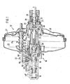
- the master brake cylinder 10 is provided with a brake booster 12 and has a filling stage 14.
- the master brake cylinder 10 supplies two brake circuits in a known manner, the connections of which are indicated by the reference numerals 16 and 18.
- the force applied by the driver via a brake pedal (not shown) is introduced into the master brake cylinder 10 via a tappet 20.
- the valve elements 22, 26 and the valve seats 24, 28 control the brake booster 12 in a known manner. If the tappet 20 is moved to the left in FIG. 1, the annularly elastic valve element 22 lies on the associated valve seat 24 and disconnects the connection between the Chambers 25 and 27 of the brake booster, between which the movable wall 29 is arranged. Upon further movement, the annular valve element 26, which is formed in one piece with the valve element 22, separates from the associated valve seat 28 and air under atmospheric pressure (p 2 ) can flow into the overpressure chamber 27.
- the filling piston 34 is provided at its front end with a nose 36 which engages behind a nose 40 of an annular piston 38.
- the filling piston 34 and the ring piston 38 are telescopically connected to one another, i.e. the filling piston 34 can be inserted into the annular piston 38.
- the filling chamber 42 is enclosed within the annular piston 38. Seals 44, 46 seal the outer space 45 of the annular piston 38. This outer space 45 is connected via an opening 47 to the vacuum chamber 25 of the brake booster 12.
- the filling chamber 42 concentrically surrounds the high pressure chamber 58 of the master brake cylinder 10. Via a channel 50, a chamber 52 and a further channel 54, the filling chamber 42 is with a Hydraulic-liquid reservoir 61 under atmospheric pressure can be connected. The connection is opened or closed by valve 60.
- a sealing sleeve 56 is arranged between the filling chamber 42 and the high-pressure chamber 48 and allows hydraulic fluid to pass from the filling chamber into the high-pressure chamber.
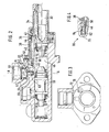
- the valve 60 is shown in detail in FIG. 2. It connects the filling chamber 42 to the hydraulic fluid reservoir 61, but is controlled by the pressure in the high pressure chamber 48.
- a control piston 62 is used, which is sealingly guided through the seal 63 in the channel between the high-pressure chamber 48 and valve 60.
- the control piston 62 acts on a valve plate 64, which is pressed onto the seal 66 by a spring 67.
- FIG. 3 shows a channel 70 and a transverse bore 72, which connect the filling chamber 42 to the hydraulic fluid reservoir 61 bypassing the valve 60.
- the valve 80 is arranged in the channel 70.
- the valve 80 has a valve body 82 which is pretensioned by a spring 84 and is acted upon by the annular piston 38 in the manner described below.
- the master brake cylinder shown works as follows. Before braking begins, the components are in the position shown in FIG. 1. When the brake pedal (not shown) is actuated, the tappet 20 is moved to the left in FIG. 1 pushed. As described above, the brake booster is actuated in a known manner via the valve elements 22, 26 and valve seats 24, 28.
- the filling piston 34 is telescopically displaced in the annular piston 38 from the wall 29.
- the negative pressure P1 in the chamber 25 of the brake booster 12 is transmitted through the opening 47 into the outer space 45, which surrounds the annular piston 38.
- the outer space 45 is delimited by the seals 44 and 46. Since the annular piston 38 tapers on the left in accordance with FIGS. 1 and 2, the pressure difference between the filling chamber 42 and the outer space 45 causes the annular piston 38 to be displaced to the left in the figures. This movement of the annular piston 38 causes the valve 80 to close since the valve body 82 is pressed against the force of the spring 84 on the bore 70 (FIG. 4).
- the filling chamber 42 is thus separated from the hydraulic fluid reservoir 61 and the movement of the filling piston 34 builds up a pressure in it, which pressure is transferred to the high pressure chamber 48 by folding the sleeve 56.
- the filling chamber 42 and the high-pressure chamber 48 therefore have approximately the same pressure.
- a predetermined pressure in the filling chamber 42 (and thus also in the high-pressure chamber 48) is exceeded, the pressure acting on the surface A 1 of the valve 60 lifts the valve plate 64 against the force of the spring 67 from the seal 66, so that the pressure in the filling chamber 42 via the channel 50, the chamber 52 and the further channel 54 into the hydraulic fluid reservoir 61. This does not change the pressure in the high-pressure chamber 48.
- the spool 62 which transmits the pressure of the high pressure chamber 48 to the valve plate 64, remains in the valve 60 opening position.
- the filling level 14 is thus when a predetermined, defined by the area A l and the spring 67 cutoff pressure ineffective, that is, the filling piston 34 is moved practically without resistance, without hydraulic fluid being pumped into the brake system.
Landscapes
- Engineering & Computer Science (AREA)
- Transportation (AREA)
- Mechanical Engineering (AREA)
- Transmission Of Braking Force In Braking Systems (AREA)
- Braking Systems And Boosters (AREA)
Applications Claiming Priority (2)
| Application Number | Priority Date | Filing Date | Title |
|---|---|---|---|
| DE19853508753 DE3508753A1 (de) | 1985-03-12 | 1985-03-12 | Hauptbremszylinder mit fuellstufe |
| DE3508753 | 1985-03-12 |
Publications (2)
| Publication Number | Publication Date |
|---|---|
| EP0197307A2 true EP0197307A2 (fr) | 1986-10-15 |
| EP0197307A3 EP0197307A3 (fr) | 1987-07-22 |
Family
ID=6264933
Family Applications (1)
| Application Number | Title | Priority Date | Filing Date |
|---|---|---|---|
| EP86103001A Withdrawn EP0197307A3 (fr) | 1985-03-12 | 1986-03-06 | Maítre-cylindre de freinage ayant une chambre de remplissage rapide |
Country Status (2)
| Country | Link |
|---|---|
| EP (1) | EP0197307A3 (fr) |
| DE (1) | DE3508753A1 (fr) |
Cited By (1)
| Publication number | Priority date | Publication date | Assignee | Title |
|---|---|---|---|---|
| FR2676411A1 (fr) * | 1991-05-18 | 1992-11-20 | Teves Gmbh Alfred | Dispositif d'actionnement pour un systeme hydraulique de freinage pour vehicule automobile. |
Families Citing this family (1)
| Publication number | Priority date | Publication date | Assignee | Title |
|---|---|---|---|---|
| DE8805017U1 (de) * | 1988-04-15 | 1989-08-10 | Lucas Industries P.L.C., Birmingham, West Midlands | Hydraulische Bremsvorrichtung |
Family Cites Families (3)
| Publication number | Priority date | Publication date | Assignee | Title |
|---|---|---|---|---|
| DE2450474A1 (de) * | 1974-10-24 | 1976-04-29 | Daimler Benz Ag | Mehrkreisige bremsvorrichtung fuer fahrzeuge |
| US4086770A (en) * | 1976-11-29 | 1978-05-02 | General Motors Corporation | Dual circuit quick take-up master cylinder |
| EP0049185A3 (fr) * | 1980-09-29 | 1982-09-08 | The Bendix Corporation | Soupape de compensation pour un dispositif compresseur de liquide |
-
1985
- 1985-03-12 DE DE19853508753 patent/DE3508753A1/de not_active Withdrawn
-
1986
- 1986-03-06 EP EP86103001A patent/EP0197307A3/fr not_active Withdrawn
Cited By (1)
| Publication number | Priority date | Publication date | Assignee | Title |
|---|---|---|---|---|
| FR2676411A1 (fr) * | 1991-05-18 | 1992-11-20 | Teves Gmbh Alfred | Dispositif d'actionnement pour un systeme hydraulique de freinage pour vehicule automobile. |
Also Published As
| Publication number | Publication date |
|---|---|
| EP0197307A3 (fr) | 1987-07-22 |
| DE3508753A1 (de) | 1986-09-18 |
Similar Documents
| Publication | Publication Date | Title |
|---|---|---|
| DE2308838A1 (de) | Federspeicherbremszylinder mit be- und entlueftungsventil | |
| EP1657481A2 (fr) | Raccord rapide | |
| DE3325424A1 (de) | Betaetigungseinrichtung fuer eine hydraulische kraftfahrzeugbremsanlage | |
| DE2460529C3 (de) | Tandem-Hauptzylinder für eine mit einem Bremskraftverstärker ausgerüstete hydraulische Bremsanlage | |
| DE69301612T2 (de) | Bremskraftverstärker mit maskiertem hub | |
| EP0257360B1 (fr) | Assemblage d'un amplificateur de force de freinage et d'un maître cylindre | |
| EP0337473B1 (fr) | Système de freinage hydraulique | |
| DE3506087C2 (de) | Bremskraftverstärker für eine Zweikreisbremsanlage | |
| DE3338690A1 (de) | Einrichtung zum steuern des bremsdruckes | |
| EP0197307A2 (fr) | Maître-cylindre de freinage ayant une chambre de remplissage rapide | |
| DE3230082A1 (de) | Hydraulische bremsanlage | |
| EP0000794B1 (fr) | Robinet de commande à deux circuits | |
| DE2710143A1 (de) | Zweikreis-steuerventil | |
| DE69400912T2 (de) | Hilfskraftbremsvorrichtung mit vereinfachter automatischer steuerung | |
| DE3439086A1 (de) | Relaisventileinrichtung | |
| EP0194593B1 (fr) | Maître-cylindre ayant une chambre de remplissage rapide | |
| EP0026346B1 (fr) | Valve de freinage à commande mécanique, en particulier valve de freinage actionnée au pied pour systèmes de freinage à double circuit dans des véhicules | |
| DE4441098C2 (de) | Fremdkraftunterstützte Betätigungsvorrichtung | |
| DE1233289B (de) | Servobremsgeraet, insbesondere fuer Kraftfahrzeuge | |
| DE3327683A1 (de) | Steuerventileinrichtung | |
| DE3642760A1 (de) | Vakuumbremskraftverstaerker | |
| EP0324906B1 (fr) | Dispositif de commande d'urgence | |
| DE2820768C2 (de) | Bremsdrucksteuereinheit für eine hydraulische Fahrzeugbremsanlage | |
| DE1277047B (de) | Servobremseinrichtung, insbesondere fuer Kraftfahrzeuge (Bremsverstaerker) | |
| DE3235358A1 (de) | Lastabhaengiger bremskraftregler |
Legal Events
| Date | Code | Title | Description |
|---|---|---|---|
| PUAI | Public reference made under article 153(3) epc to a published international application that has entered the european phase |
Free format text: ORIGINAL CODE: 0009012 |
|
| AK | Designated contracting states |
Kind code of ref document: A2 Designated state(s): DE FR GB IT |
|
| PUAL | Search report despatched |
Free format text: ORIGINAL CODE: 0009013 |
|
| AK | Designated contracting states |
Kind code of ref document: A3 Designated state(s): DE FR GB IT |
|
| 17P | Request for examination filed |
Effective date: 19871030 |
|
| 17Q | First examination report despatched |
Effective date: 19890802 |
|
| 18W | Application withdrawn |
Withdrawal date: 19910906 |
|
| STAA | Information on the status of an ep patent application or granted ep patent |
Free format text: STATUS: THE APPLICATION HAS BEEN WITHDRAWN |
|
| R18W | Application withdrawn (corrected) |
Effective date: 19910906 |
|
| RIN1 | Information on inventor provided before grant (corrected) |
Inventor name: SCHLUETER, PETER |