EP0197352A1 - Méthode et dispositif pour mettre en oeuvre une interconnexion courte pour lignes à courant continu haute tension en cas de défauts de réseau - Google Patents
Méthode et dispositif pour mettre en oeuvre une interconnexion courte pour lignes à courant continu haute tension en cas de défauts de réseau Download PDFInfo
- Publication number
- EP0197352A1 EP0197352A1 EP86103430A EP86103430A EP0197352A1 EP 0197352 A1 EP0197352 A1 EP 0197352A1 EP 86103430 A EP86103430 A EP 86103430A EP 86103430 A EP86103430 A EP 86103430A EP 0197352 A1 EP0197352 A1 EP 0197352A1
- Authority
- EP
- European Patent Office
- Prior art keywords
- voltage
- control
- current
- converter
- rectifier
- Prior art date
- Legal status (The legal status is an assumption and is not a legal conclusion. Google has not performed a legal analysis and makes no representation as to the accuracy of the status listed.)
- Granted
Links
Images


Classifications
-
- H—ELECTRICITY
- H02—GENERATION; CONVERSION OR DISTRIBUTION OF ELECTRIC POWER
- H02H—EMERGENCY PROTECTIVE CIRCUIT ARRANGEMENTS
- H02H7/00—Emergency protective circuit arrangements specially adapted for specific types of electric machines or apparatus or for sectionalised protection of cable or line systems, and effecting automatic switching in the event of an undesired change from normal working conditions
- H02H7/26—Sectionalised protection of cable or line systems, e.g. for disconnecting a section on which a short-circuit, earth fault, or arc discharge has occured
- H02H7/268—Sectionalised protection of cable or line systems, e.g. for disconnecting a section on which a short-circuit, earth fault, or arc discharge has occured for DC systems
-
- H—ELECTRICITY
- H02—GENERATION; CONVERSION OR DISTRIBUTION OF ELECTRIC POWER
- H02J—ELECTRIC POWER NETWORKS; CIRCUIT ARRANGEMENTS OR SYSTEMS FOR SUPPLYING OR DISTRIBUTING ELECTRIC POWER; SYSTEMS FOR STORING ELECTRIC ENERGY
- H02J3/00—Circuit arrangements for AC mains or AC distribution networks
- H02J3/36—Arrangements for transfer of electric power between AC networks via high-voltage DC [HVDC] links; Arrangements for transfer of electric power between generators and networks via HVDC links
-
- H—ELECTRICITY
- H02—GENERATION; CONVERSION OR DISTRIBUTION OF ELECTRIC POWER
- H02M—APPARATUS FOR CONVERSION BETWEEN AC AND AC, BETWEEN AC AND DC, OR BETWEEN DC AND DC, AND FOR USE WITH MAINS OR SIMILAR POWER SUPPLY SYSTEMS; CONVERSION OF DC OR AC INPUT POWER INTO SURGE OUTPUT POWER; CONTROL OR REGULATION THEREOF
- H02M7/00—Conversion of AC power input into DC power output; Conversion of DC power input into AC power output
- H02M7/66—Conversion of AC power input into DC power output; Conversion of DC power input into AC power output with possibility of reversal
- H02M7/68—Conversion of AC power input into DC power output; Conversion of DC power input into AC power output with possibility of reversal by static converters
- H02M7/72—Conversion of AC power input into DC power output; Conversion of DC power input into AC power output with possibility of reversal by static converters using discharge tubes with control electrode or semiconductor devices with control electrode
- H02M7/75—Conversion of AC power input into DC power output; Conversion of DC power input into AC power output with possibility of reversal by static converters using discharge tubes with control electrode or semiconductor devices with control electrode using devices of a thyratron or thyristor type requiring extinguishing means
- H02M7/757—Conversion of AC power input into DC power output; Conversion of DC power input into AC power output with possibility of reversal by static converters using discharge tubes with control electrode or semiconductor devices with control electrode using devices of a thyratron or thyristor type requiring extinguishing means using semiconductor devices only
- H02M7/7575—Conversion of AC power input into DC power output; Conversion of DC power input into AC power output with possibility of reversal by static converters using discharge tubes with control electrode or semiconductor devices with control electrode using devices of a thyratron or thyristor type requiring extinguishing means using semiconductor devices only for high voltage direct transmission link
-
- Y—GENERAL TAGGING OF NEW TECHNOLOGICAL DEVELOPMENTS; GENERAL TAGGING OF CROSS-SECTIONAL TECHNOLOGIES SPANNING OVER SEVERAL SECTIONS OF THE IPC; TECHNICAL SUBJECTS COVERED BY FORMER USPC CROSS-REFERENCE ART COLLECTIONS [XRACs] AND DIGESTS
- Y02—TECHNOLOGIES OR APPLICATIONS FOR MITIGATION OR ADAPTATION AGAINST CLIMATE CHANGE
- Y02E—REDUCTION OF GREENHOUSE GAS [GHG] EMISSIONS, RELATED TO ENERGY GENERATION, TRANSMISSION OR DISTRIBUTION
- Y02E60/00—Enabling technologies; Technologies with a potential or indirect contribution to GHG emissions mitigation
- Y02E60/60—Arrangements for transfer of electric power between AC networks or generators via a high voltage DC link [HVCD]
Definitions
- the invention relates to a method for operating a high-voltage direct-current transmission short coupling in the event of a network fault in one of the two alternating-voltage networks connected to the direct-current transmission path via a converter.
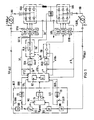
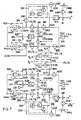
- FIG. 1 the structure of such a HVDC short coupling is shown, in which the two networks NA and NB are each coupled via a converter SRA, SRB and the actual DC transmission link, the HVDC link consisting in the simplest case of a choke coil L.
- a converter transformer is connected upstream of the converters on the alternating current side, the transmission ratio of which can be adjusted by certain transmission stages ⁇ üA, AüB compared to an average value.
- several individual converters are often connected to the AC side via individual transformers. and connected in series on the DC side in order to enable higher-pulse operation of the respective converter arrangement. To clarify the invention, however, only the control of a converter is explained in each case.
- the valves of the converters each receive an ignition pulse from a control set STA or STB such that, in the structure of the control arrangement shown schematically in FIG. 1, the converter SRA in the network NA draws a current which can be controlled by the control voltage USTA (rectifier operation of the converter SRA in station A ), while the converter SRB arranged in station B works as an inverter and feeds into the network NB and controls this feed via its control voltage USTB in such a way that a DC voltage UdB which can be measured by means of a voltage measuring element is maintained at the HVDC.
- a central control unit STZ provides a target value ld * for the HVDC direct current Id measured by means of a measuring device, the control difference of which is corrected by a current regulator RIA.
- the output signal ⁇ aA of the current regulator can be used directly as a control voltage for the headset STA.
- VPA 84 P 3439 E the measured value UdB be replaced by a model value, which in the central control device STZ is controlled by a control and Calculator RZ can be calculated from the actual current value Id, the amplitudes UA and UB of the networks NA and NB, the control angle or the extinction angle -yB of the station B and a parameter dx for the inductive voltage drop of the converters.
- VLA linearization element
- the linearization can also be carried out in another way.
- the pilot control quantity supplied to the pilot control device VA is also referred to as the rectifier pilot control angle aGv if it (such as the voltage UdB in FIG. 1) does not yet have the dimension of an angle, but only ver within the pilot control device to the controller output signal ⁇ A is linked that the control angle ⁇ A is the sum of the pilot angle given by the pilot variable and an angle correction given by the control output signal.
- overlap angle u
- overlap angle u
- the control and computing element RZ for each desired extinction angle ⁇ x corresponding to the instantaneous values of the HVDC current Id and the network amplitude UB. Therefore, this pre-calculated overlap angle.
- u implemented together with the output signal ⁇ B of a ⁇ controller RGB in a pilot control device VB to the control voltage USTB, it is possible to control the converter SRB to the desired DC voltage via an inverter control angle aB.
- the pilot control variable for this pilot control device VB which determines the overlap angle u, is referred to below as -yWv, a separate linearization element becoming partially superfluous and can be replaced in FIG. 1 by an amplifier for level adjustment.
- -yWv a separate linearization element becoming partially superfluous and can be replaced in FIG. 1 by an amplifier for level adjustment.
- the design of the pilot control device can largely be adapted to the respective applications.
- the central control unit STZ can form the setpoints ld *, ⁇ * and the pilot signals ⁇ Wv and possibly aGv, information about the amplitudes UA, UB of the networks NA, NB and their undisturbed state is required, which can be obtained from a network voltage control device NCT - ("Network monitor") is tapped, the further function shown in Figure 3 will be discussed in detail.
- NCT - Network monitor
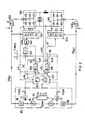
- FIG. 2 shows the same HVDC with its converters SRA, SRB, their transformers and control sets STA, STB, but now the converter SRA of station A is used as an inverter and the converter SRB of station B is used as a rectifier.
- control rate STB of the converter SRB working as a rectifier is now controlled by a current regulator RIB and is precontrolled with a precontrol signal ⁇ Gv, which is either tapped at the output DC voltage UdA of the rectifier SRA or is provided as a model value by the computing element RZ of the central control device STZ .
- the control voltage USTA for the control set STA of the converter SRA operated as an inverter is formed by an extinction angle regulator RGA which is now assigned to station A and is precontrolled with the inverter pilot control variable aWv.
- the inverter station is supplemented by a marginal current control, which is omitted in Figure 1 for the inverter station B for the sake of clarity and is also not prescribed for all HVDC systems. This is because an operating state can occur in which the maintenance of the desired direct current is not achieved by regulating the current feed in the rectifier station and therefore the HVDC transmission power is not fully utilized.
- the output signal of the current regulator RIA is engaged and switched through to the control line for USTA in order to increase the direct current Id by changing the control angle.
- the selection circuit ASA switches the output signal of this extinguishing angle regulation through to the control line USTA, the current regulator RIA thus disengages and runs because it is Controlled system is now interrupted, to the stop.
- the selection circuit ASA therefore takes care of the replacement between the regulators RIA and RGA in order to maintain at least the current Id * img in the HVDC transmission.
- the HVDC operating mode previously explained with reference to FIGS. 1 and 2 requires a three-phase voltage system in each of the two stations, the phase voltages of which each have approximately a nominal value specified for the undisturbed network state or are at least symmetrical. A dip or breakdown of one or two phase voltages leads to an asymmetrical voltage system. If one phase fails, the other two phases of a three-phase network can still transmit 66% of the output power, but the DC transmission in HVDC has a much lower value.
- the aim is therefore not to interrupt the energy transfer for the close coupling, but even to maintain the greatest possible energy transport, at least in the case of single-pole faults which have the largest statistical proportion of network faults, but preferably also in the case of two-pole faults.
- the deviation of the voltage amplitude from a predetermined nominal value or, more generally, the error-related change in the voltage amplitude is detected at the phases of the network disturbed by the network fault (advantageously at each phase of the disturbed network) and converted to a first pilot control variable.
- This first pilot control variable is specified in such a way that the direct current, which is normally determined by the current regulator of the rectifier station or by the marginal current regulator of the inverter station, can be kept at a high level, for example the nominal current or the specified current setpoint value Id ".
- This first pilot control variable becomes the control voltage of the "disturbed" converter connected to the faulty network in such a way that the HVDC direct voltage is thereby reduced.
- a second pilot control voltage is obtained, which acts as a pilot variable for the control angle of the other - “undisturbed "Current converter.
- This can be done, for example, by the DC voltage of the faulty converter taking into account the DC voltage-proportional voltage drop in the system as the setpoint value and as the actual value, the output DC voltage of the voltage regulator is connected, which forms the second pilot variable.
- the amplitudes (or the rms values by means of a corresponding measuring element) of the individual phase voltages are detected for each station by means of a magnitude image BB (FIG. 1) in order to be checked in a threshold value step SS for falling below a limit value Ug limit will. If one or more voltage amplitudes drop, a fault memory MS is set which, for the duration of the fault, emits a corresponding fault signal FA or FB which reports the network fault of the station in question.
- the phase voltage with the lowest voltage amplitude, i.e. the greatest voltage drop is selected by an extreme value selection circuit ES (in the case of FIG. 1 a maximum selection) and determines the value AUA or AUB of the voltage change caused by the network error to be taken into account.
- the smallest voltage change is first selected from the amplitudes of the phase voltages by means of a minimum selection and the change in the voltage amplitude is formed by comparison with the nominal voltage corrected by the transmission ratio.
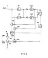
- FIG. 7 This is the case in FIG. 7 provided, in which both stations enable both rectifier and inverter operation.
- a setpoint P * for the power to be transmitted which is predetermined for the operating state can also be called up and which, together with an actual value P formed in a suitable manner (not shown), is fed to a reference variable controller RP in order to derive a preliminary setpoint ld * therefrom. * to build.
- Other reference variables can also be provided for forming the current setpoint value, which lead to a different structure of the reference variable regulation.
- this provisional direct current setpoint ld ** is fed to a ramp generator HG, which e.g. serves to let the current setpoint ramp up according to a predetermined ramp function after a complete shutdown of the HVDC when restarting, as is described in the European patent application 84 11 3024.8 mentioned.
- this current limitation is achieved in that the ramp-up generator HG has the value ldO stored in the computing element RZ applied as a limit value of the ramp-function generator via a corresponding switch controlled during the fault. This means that the power regulator RP which is in the stop is disengaged and instead of the provisional current sol value ld ** only the stored value ldO is specified.
- the HVDC voltage for example the minimum value of the HVDC voltage at the output of the two converters selected using a minimum selection EU
- a predetermined value of, for example, 0.5 times the nominal DC voltage it can be advantageous to reduce this HVDC limit value -Hold DC voltage at the expense of a sinking HVDC direct current.
- the reaching of this threshold value is detected in FIG. 3 by means of a threshold value element SU.
- the difference between a nominal voltage value Udn stored in the computing element RZ and the HVDC direct voltage actual value switched through by the minimum selection EU is transferred via a semiconductor switch to a proportional element PG, which now has the limited current setpoint specified by the ramp generator until the specified limit value of the voltage builds up in the HVDC.
- the final current setpoint value ld * formed in this way is then supplied to the current regulator RIA or RIB, which is respectively engaged, as a setpoint value in the two stations.
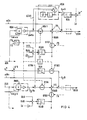
- control and computing element RZ In addition to storing the values P *, "mode”, ldO and Udn belonging to the respectively predefined operating state, the control and computing element RZ also has the task of forming the pilot control variable aWv and aGv belonging to the respective operating state, as described in the European patent application mentioned is described. It also provides a rectifier ignition angle control value a0 or cos aO and an inverter extinction angle control value y0 or cos ⁇ O, which in the event of a fault serve to correct or replace the output signals ⁇ A and ⁇ v shown in FIG. 1.
- a switch SFA1 which, like the switches indicated in FIG. 3 and all other switches used, is advantageously designed as a transistor switch, is connected to an error signal (FA, FB), which is e.g.
- the actual value of the DC connection voltage UdA of station A is applied to this correction controller as the setpoint, which is preferably reduced by the voltage drop proportional to the direct current Id.
- the actual value of the DC connection voltage UdB of the inverter serves as the actual value.
- the voltage correction controller RUdB thus also regulates the DC connection voltage of the inverter via the second pilot control variable ⁇ UdB acting on the inverter in such a way that the reset of the HVDC voltage caused by the first pilot control variable ⁇ AO in the rectifier is also correctly taken into account in inverter operation.
- a switch SFB3 is opened via a pulse shaper IF, by means of which the extinction angle controller RGB of the inverter is blocked.
- cos ⁇ is formed from the error-related deviation ⁇ UB of the voltage amplitude and the predetermined inverter extinction angle control signal cos ⁇ 0 by multiplication and suitable amplification.
- the pulse shaper IF advantageously contains a time lapse, which only switches on the extinction angle controller RGB after the end of the error with a time delay.
- FIG. 4 also shows a gradient detection GDA which serves to form two correction variables ⁇ lAA, ⁇ lBA.
- the slight ignition angle correction by the output signal ⁇ A of the current regulator RIA can namely remain switched on even during the mains fault.
- the output signal ⁇ A of the current regulator RIA indicates whether a positive or a negative change in the actual value ld is required to maintain the current setpoint ld * in the event of a fault. If the gradient of the signal ⁇ A is positive because the current regulator requires more current, a correction variable derived from ⁇ aA can be applied to an input of the pilot control device VB to correct the control angle of the opposite station.
- a corresponding signal can be applied to an input of the pilot control device VA as a correction value for the ignition angle of the own rectifier station.
- a proportional controller PP with an integrator IP in its return provides the gradient at its output, which is fed to a polarity-separated limit signaling circuit.
- both limit value detectors GG1 and GG2 drop and trigger a pulse stage IPF via a logic gate LL.
- the pulse thus formed leads to the fact that the controlled memory-hold circuit now stores this value in accordance with the previously occurring sign of the gradient in order to provide it as a correction value for the respective pilot control device for the duration of the network fault.
- station A is operated as an inverter station and station B is operated as a rectifier station, as shown in FIGS. 2 and 6, then those components are provided and engaged for each station that are explained in FIG. 4 for the opposite station were.
- an arithmetic logic unit RWA (FIG. 6) consisting of AUA and ⁇ O an inverter deletion angle pilot control quantity ⁇ AO.
- the error signal FA 1, which is assigned to a voltage drop in the network NA, now denotes an error in the network connected to the inverter station.
- the switch SFA4 is closed during the fault duration, the inverter pre-control variable ⁇ AO is used to correct the inverter pre-control variable aWv, which is also formed during undisturbed operation, while the extinguishing angle controller RGA is blocked via a switch SFA3 and only released again after the fault has ended.
- the switch SFA5, which is closed only in the event of an error in the opposite network B (error signal FB 1), is open in the event of an error in station A itself and disables the voltage correction regulator RUdA.
- the extreme value selection circuit ASA replaces the extinguishing angle regulator RGA by the current regulator RIA when the direct current actual value Id drops below the target value ld * -Imarg specified by the maginal current regulation. As long as the selection circuit ASA engages the extinction angle regulator RGA and the controlled system of the current regulator RIA opens, the current regulator output signal ⁇ A is practically at its extreme value and the gradient detection GDA does not respond.
- the marginal current control with a corresponding current controller RIB and a selection circuit ASB which is in principle also provided in FIG. 4 for the station B operated there as an inverter, is not shown in FIG. 4.
- this correction variable is precontrolled when the switch SFB1 is closed with the value ⁇ BO, which is formed by the computing element RGB in accordance with the product of AUB and cos aO.
- the gradient detection GDB now forms the signal AIBB derived from the current regulator RIB, which is used for the control voltage correction of the own station B, and the corresponding signal AIAB, which is used for the control voltage correction of the opposite station, in accordance with the respective sign of the detected gradient.
- the switches GZ1 B, GZ2B at the output of these signals are closed when the rectifier operation of station B is being considered.
- a status signal "mode” can be used to switch between a mode with rectifier operation in station A and inverter operation in station B (FIGS. 1 and 4) and a mode with rectifier operation in station B and inverter operation in station A (FIG. 2 and 6) can be switched.
- a mode with rectifier operation in station A and inverter operation in station B FIGS. 1 and 4
- a mode with rectifier operation in station B and inverter operation in station A FIG. 2 and 6
- the respective current controller is switched on in both operating modes, whereby it is operated as a margina current regulator when the inverter is in operation (switch SAW or SBW closed) and the input is switched off by switching off the rectifier pilot variable (switch SAG2 or SGB2 open) Selection circuit (ASA or ASB) is connected, the other input of which is connected to the inverter control chain to which the extinguishing angle controller output variable ( ⁇ A or ⁇ B) is applied (switch SAW2 or SBW 2 closed).
- ASA or ASB the other input of which is connected to the inverter control chain to which the extinguishing angle controller output variable ( ⁇ A or ⁇ B) is applied (switch SAW2 or SBW 2 closed).
- Both control chains of a single station have a voltage correction controller (RUdA or RUdB) in common, which can only intervene via the switches SFA2 and SFA5 (station A) or SFB2 and SFB5 in the currently switched-on inverter or rectifier control chain of the control voltage.
- the status signal assigned to the corresponding operation controls these switches via an AND link with the error signal indicating the error of the remote station in such a way that the voltage correction controller corrects the control voltage of this station only in the event of an error in the remote station.
- the switch positions in FIG. 7 indicate rectifier operation of station A, inverter operation of station B, a rectifier-side network fault and an unavailable marginal current control in the inverter station (B).
- FIG. 1 and FIG. 2 it is indicated in the circuit block of the control sets STA, STB that the valves operating on separate phases of the respective converter are advantageously ignited by individual control sets. This enables the ignition pulses to be synchronized with the asymmetrical phase voltages in the event of an asymmetrical fault. It may also be necessary for the control of the valves working on one phase of the disturbed AC voltage network each form their own control voltage.
- microcomputers are used in each station for the formation of the pilot control variables and the control voltages.
Landscapes
- Engineering & Computer Science (AREA)
- Power Engineering (AREA)
- Supply And Distribution Of Alternating Current (AREA)
- Rectifiers (AREA)
- Inverter Devices (AREA)
- Direct Current Feeding And Distribution (AREA)
Priority Applications (1)
| Application Number | Priority Date | Filing Date | Title |
|---|---|---|---|
| AT86103430T ATE44337T1 (de) | 1985-03-27 | 1986-03-14 | Verfahren und vorrichtung zum betrieb einer hgue- kurzkupplung bei netzfehlern. |
Applications Claiming Priority (2)
| Application Number | Priority Date | Filing Date | Title |
|---|---|---|---|
| DE3511163 | 1985-03-27 | ||
| DE3511163 | 1985-03-27 |
Publications (2)
| Publication Number | Publication Date |
|---|---|
| EP0197352A1 true EP0197352A1 (fr) | 1986-10-15 |
| EP0197352B1 EP0197352B1 (fr) | 1989-06-28 |
Family
ID=6266515
Family Applications (1)
| Application Number | Title | Priority Date | Filing Date |
|---|---|---|---|
| EP86103430A Expired EP0197352B1 (fr) | 1985-03-27 | 1986-03-14 | Méthode et dispositif pour mettre en oeuvre une interconnexion courte pour lignes à courant continu haute tension en cas de défauts de réseau |
Country Status (6)
| Country | Link |
|---|---|
| US (1) | US4727467A (fr) |
| EP (1) | EP0197352B1 (fr) |
| JP (1) | JPS61227637A (fr) |
| AT (1) | ATE44337T1 (fr) |
| CA (1) | CA1277369C (fr) |
| DE (1) | DE3664179D1 (fr) |
Cited By (4)
| Publication number | Priority date | Publication date | Assignee | Title |
|---|---|---|---|---|
| WO1991001061A1 (fr) * | 1989-07-11 | 1991-01-24 | Siemens Aktiengesellschaft | Procede et dispositif pour relayer la regulation de plusieurs grandeurs de reglage d'un convertisseur |
| WO1992022118A1 (fr) * | 1991-05-27 | 1992-12-10 | Siemens Aktiengesellschaft | Procede de circuit pour la transmission de courant continu |
| WO1995031847A1 (fr) * | 1994-05-18 | 1995-11-23 | Asea Brown Boveri Ab | Recuperation de puissance transmise dans une installation de transmission de courant continu haute tension |
| DE102012107602A1 (de) | 2012-08-20 | 2014-05-22 | Technische Universität Clausthal | Kopplung von Wechselspannungs-Energieversorgungsnetzen |
Families Citing this family (11)
| Publication number | Priority date | Publication date | Assignee | Title |
|---|---|---|---|---|
| DE3866584D1 (de) * | 1987-05-15 | 1992-01-16 | Siemens Ag | Zustandssignalbildung zur anzeige des ueberganges in die betriebsart "bypass" bei einer einrichtung zur hochspannungsgleichstromuebertragung. |
| US4884181A (en) * | 1987-08-26 | 1989-11-28 | Siemens Aktiengesellschaft | Method and arrangement for controlling a high voltage d-c transmission system |
| EP0315871A1 (fr) * | 1987-11-12 | 1989-05-17 | Siemens Aktiengesellschaft | Procédé et dispositif de contrôle d'un redresseur de courant sur un réseau asymétrique |
| DE3743997A1 (de) * | 1987-12-23 | 1988-11-17 | Siemens Ag | Verfahren und vorrichtung zur entkopplung der wirk- und blindleistungsregelung bei einer zwei netze verbindenden hochspannungs-gleichstrom-uebertragungsstrecke |
| JPH04190633A (ja) * | 1990-11-21 | 1992-07-09 | Hitachi Ltd | インバータの並列運転方法および並列運転インバータ装置 |
| JP3311214B2 (ja) * | 1995-09-05 | 2002-08-05 | 東京電力株式会社 | 電力変換装置の制御装置 |
| SE520658C2 (sv) * | 1997-03-24 | 2003-08-05 | Abb Ab | Anläggning för överföring av elektrisk effekt mellan likspänningsnät och växelspänningsnät |
| DE102004013131A1 (de) * | 2004-03-17 | 2005-10-06 | Siemens Ag | Windkraftanlage |
| JP4673428B2 (ja) * | 2006-06-30 | 2011-04-20 | アーベーベー・テヒノロギー・アーゲー | Hvdcシステム及びhvdcシステムの電圧源変換器の制御方法 |
| US12074535B2 (en) * | 2019-04-25 | 2024-08-27 | Mitsubishi Electric Corporation | Control device and power conversion device |
| CN112886627B (zh) * | 2021-01-15 | 2022-08-09 | 长沙理工大学 | 一种提升mmc供电无源网络功率传输能力的方法 |
Citations (1)
| Publication number | Priority date | Publication date | Assignee | Title |
|---|---|---|---|---|
| EP0142096A2 (fr) * | 1983-11-09 | 1985-05-22 | Siemens Aktiengesellschaft | Procédé et dispositif pour une ligne de transmission à courant continu à haute tension avec dérivation en cas de panne |
Family Cites Families (6)
| Publication number | Priority date | Publication date | Assignee | Title |
|---|---|---|---|---|
| US4177507A (en) * | 1978-03-22 | 1979-12-04 | General Electric Company | Method and control for maintaining optimum performance of HVDC power transmission systems at rectifier end during A. C. system fault |
| DE2901263C2 (de) * | 1979-01-13 | 1985-05-23 | Brown, Boveri & Cie Ag, 6800 Mannheim | Regelung einer HGÜ-(Hochspannungs-Gleichstrom- Übertragungs-)-Kurzkupplung |
| DE3029358A1 (de) * | 1980-08-01 | 1982-03-11 | Siemens AG, 1000 Berlin und 8000 München | Einrichtung zur ueberbrueckung von kurzzeitigen netzausfaellen bei spannungszwischenkreis-umrichtern |
| SE430452B (sv) * | 1982-03-04 | 1983-11-14 | Asea Ab | Styrsystem for likstromskraftoverforing |
| US4475150A (en) * | 1982-04-28 | 1984-10-02 | General Electric Company | Coordinated load commutated inverter protection system |
| JPS60249824A (ja) * | 1984-05-24 | 1985-12-10 | 株式会社東芝 | 交直変換装置の制御方法 |
-
1986
- 1986-03-14 EP EP86103430A patent/EP0197352B1/fr not_active Expired
- 1986-03-14 DE DE8686103430T patent/DE3664179D1/de not_active Expired
- 1986-03-14 AT AT86103430T patent/ATE44337T1/de not_active IP Right Cessation
- 1986-03-21 US US06/842,511 patent/US4727467A/en not_active Expired - Fee Related
- 1986-03-24 JP JP61065558A patent/JPS61227637A/ja active Pending
- 1986-03-25 CA CA000505010A patent/CA1277369C/fr not_active Expired - Lifetime
Patent Citations (1)
| Publication number | Priority date | Publication date | Assignee | Title |
|---|---|---|---|---|
| EP0142096A2 (fr) * | 1983-11-09 | 1985-05-22 | Siemens Aktiengesellschaft | Procédé et dispositif pour une ligne de transmission à courant continu à haute tension avec dérivation en cas de panne |
Non-Patent Citations (2)
| Title |
|---|
| PROCEEDINGS OF THE IEE, Band 127, Nr. 1, Teil C, Januar 1980, Seiten 15-19, Stev., Herts., GB; J. ARRILAGA et al.: "Fault studies in a.c. systems interconnected by h.v.d.c. links" * |
| PROCEEDINGS OF THE IEE, Band 131, Nr. 4, Teil C, Juli 1984, Seiten 129-139 Stev., Herts., GB; G. GALANOS et al.: "Combined control and protection system for improved performance of HVDC links in the presence of AC faults" * |
Cited By (7)
| Publication number | Priority date | Publication date | Assignee | Title |
|---|---|---|---|---|
| WO1991001061A1 (fr) * | 1989-07-11 | 1991-01-24 | Siemens Aktiengesellschaft | Procede et dispositif pour relayer la regulation de plusieurs grandeurs de reglage d'un convertisseur |
| US5220493A (en) * | 1989-07-11 | 1993-06-15 | Siemens Aktiengesellschaft | Override closed loop control of several controlled variables |
| WO1992022118A1 (fr) * | 1991-05-27 | 1992-12-10 | Siemens Aktiengesellschaft | Procede de circuit pour la transmission de courant continu |
| US5479332A (en) * | 1991-05-27 | 1995-12-26 | Siemens Aktiengesellschaft | System avoiding regulator detachments in quasi-steady operation of ADC power transmission line |
| WO1995031847A1 (fr) * | 1994-05-18 | 1995-11-23 | Asea Brown Boveri Ab | Recuperation de puissance transmise dans une installation de transmission de courant continu haute tension |
| DE102012107602A1 (de) | 2012-08-20 | 2014-05-22 | Technische Universität Clausthal | Kopplung von Wechselspannungs-Energieversorgungsnetzen |
| DE102012107602B4 (de) * | 2012-08-20 | 2018-01-18 | Technische Universität Clausthal | Kopplung von Wechselspannungs-Energieversorgungsnetzen |
Also Published As
| Publication number | Publication date |
|---|---|
| DE3664179D1 (en) | 1989-08-03 |
| ATE44337T1 (de) | 1989-07-15 |
| EP0197352B1 (fr) | 1989-06-28 |
| CA1277369C (fr) | 1990-12-04 |
| US4727467A (en) | 1988-02-23 |
| JPS61227637A (ja) | 1986-10-09 |
Similar Documents
| Publication | Publication Date | Title |
|---|---|---|
| DE2904786C2 (de) | Verfahren zur Regelung von Wechselrichtern im Parallelbetrieb und Schaltungsanordnungen zur Durchführung des Verfahrens | |
| EP0197352B1 (fr) | Méthode et dispositif pour mettre en oeuvre une interconnexion courte pour lignes à courant continu haute tension en cas de défauts de réseau | |
| DE3225285C2 (de) | Verfahren zum Betrieb einer Hochspannungs-Gleichstrom-Übertragungsanlage mit beliebig vielen Umformerstationen | |
| CH615303A5 (fr) | ||
| DE69526404T2 (de) | Verfahren und Vorrichtung zur Steuerung einer serienkompensierten Wechselrichteranlage | |
| EP0703652A1 (fr) | Méthode et appareil pour une allocation variable d'un convertiseur en fonctionemment avec au moins une charge | |
| DE2901263A1 (de) | Regelung einer hgue-(hochspannungs- gleichstrom-uebertragungs-)-kurzkupplung | |
| EP1927186B1 (fr) | Procede de reglage pour une transmission de courant continu a l'aide de plusieurs convertisseurs de courant | |
| DE2827443C2 (de) | Gesicherte Stromrichteranordnung | |
| DE3326947A1 (de) | Verfahren und schaltungsanordnung zum betrieb einer hochspannungs-gleichstrom-verbindung zwischen zwei wechselspannungsnetzen | |
| DE2705242A1 (de) | Verfahren zur steuerung des wirk- und blindleistungsverhaltens einer hochspannungs-gleichstrom-uebertragungsanlage (hgue-anlage) und regelanordnung zur durchfuehrung des verfahrens | |
| DE2707974A1 (de) | Verfahren und einrichtung zur regelung einer dampfturbinenanlage | |
| DE3703218A1 (de) | Strombegrenzung fuer einen dreiphasigen, mit einer folgeregelung betriebenen wechselrichter | |
| DE1588067B1 (de) | Regelungseinrichtung einer Hochspannungs-Gleichstrom-UEbertragungsanlage fuer den Mehrpunktnetzbetrieb | |
| DE2538493A1 (de) | Hochspannungsgleichstromuebertragungsanlage | |
| EP0689729B1 (fr) | Procede et agencement de regulation pour la transmission de courant continu | |
| EP0142096B1 (fr) | Procédé et dispositif pour une ligne de transmission à courant continu à haute tension avec dérivation en cas de panne | |
| EP0315871A1 (fr) | Procédé et dispositif de contrôle d'un redresseur de courant sur un réseau asymétrique | |
| DE4420600C1 (de) | Verfahren und Anordnung zur Gleichstromübertragung | |
| EP0146726B1 (fr) | Procédé et dispositif pour mettre en oeuvre une ligne de transmission à courant continu à haute tension avec commande d'angle d'avance de phase du convertisseur | |
| DE3622787C2 (fr) | ||
| EP0586369B1 (fr) | Procede de circuit pour la transmission de courant continu | |
| EP0146725B1 (fr) | Procédé et dispositif pour mettre en oeuvre une ligne de transmission à courant continu haute tension | |
| DE1943840C3 (de) | Vorrichtung zum Verbinden zweier Wechselstromnetze | |
| EP0397913B1 (fr) | Dispositif redresseur |
Legal Events
| Date | Code | Title | Description |
|---|---|---|---|
| PUAI | Public reference made under article 153(3) epc to a published international application that has entered the european phase |
Free format text: ORIGINAL CODE: 0009012 |
|
| AK | Designated contracting states |
Kind code of ref document: A1 Designated state(s): AT CH DE FR GB LI SE |
|
| 17P | Request for examination filed |
Effective date: 19861106 |
|
| 17Q | First examination report despatched |
Effective date: 19881003 |
|
| GRAA | (expected) grant |
Free format text: ORIGINAL CODE: 0009210 |
|
| AK | Designated contracting states |
Kind code of ref document: B1 Designated state(s): AT CH DE FR GB LI SE |
|
| REF | Corresponds to: |
Ref document number: 44337 Country of ref document: AT Date of ref document: 19890715 Kind code of ref document: T |
|
| REF | Corresponds to: |
Ref document number: 3664179 Country of ref document: DE Date of ref document: 19890803 |
|
| ET | Fr: translation filed | ||
| GBT | Gb: translation of ep patent filed (gb section 77(6)(a)/1977) | ||
| PLBE | No opposition filed within time limit |
Free format text: ORIGINAL CODE: 0009261 |
|
| STAA | Information on the status of an ep patent application or granted ep patent |
Free format text: STATUS: NO OPPOSITION FILED WITHIN TIME LIMIT |
|
| 26N | No opposition filed | ||
| PGFP | Annual fee paid to national office [announced via postgrant information from national office to epo] |
Ref country code: AT Payment date: 19920226 Year of fee payment: 7 |
|
| PGFP | Annual fee paid to national office [announced via postgrant information from national office to epo] |
Ref country code: GB Payment date: 19920228 Year of fee payment: 7 |
|
| PGFP | Annual fee paid to national office [announced via postgrant information from national office to epo] |
Ref country code: FR Payment date: 19920323 Year of fee payment: 7 |
|
| PGFP | Annual fee paid to national office [announced via postgrant information from national office to epo] |
Ref country code: SE Payment date: 19920324 Year of fee payment: 7 |
|
| PGFP | Annual fee paid to national office [announced via postgrant information from national office to epo] |
Ref country code: DE Payment date: 19920521 Year of fee payment: 7 |
|
| PGFP | Annual fee paid to national office [announced via postgrant information from national office to epo] |
Ref country code: CH Payment date: 19920622 Year of fee payment: 7 |
|
| PG25 | Lapsed in a contracting state [announced via postgrant information from national office to epo] |
Ref country code: GB Effective date: 19930314 Ref country code: AT Effective date: 19930314 |
|
| PG25 | Lapsed in a contracting state [announced via postgrant information from national office to epo] |
Ref country code: SE Effective date: 19930315 |
|
| PG25 | Lapsed in a contracting state [announced via postgrant information from national office to epo] |
Ref country code: LI Effective date: 19930331 Ref country code: CH Effective date: 19930331 |
|
| GBPC | Gb: european patent ceased through non-payment of renewal fee |
Effective date: 19930314 |
|
| PG25 | Lapsed in a contracting state [announced via postgrant information from national office to epo] |
Ref country code: FR Effective date: 19931130 |
|
| REG | Reference to a national code |
Ref country code: CH Ref legal event code: PL |
|
| PG25 | Lapsed in a contracting state [announced via postgrant information from national office to epo] |
Ref country code: DE Effective date: 19931201 |
|
| REG | Reference to a national code |
Ref country code: FR Ref legal event code: ST |
|
| EUG | Se: european patent has lapsed |
Ref document number: 86103430.4 Effective date: 19931008 |