EP0197394A2 - Actuateur électromagnétique et mémoire à disque magnétique utilisant celui-ci - Google Patents
Actuateur électromagnétique et mémoire à disque magnétique utilisant celui-ci Download PDFInfo
- Publication number
- EP0197394A2 EP0197394A2 EP86103855A EP86103855A EP0197394A2 EP 0197394 A2 EP0197394 A2 EP 0197394A2 EP 86103855 A EP86103855 A EP 86103855A EP 86103855 A EP86103855 A EP 86103855A EP 0197394 A2 EP0197394 A2 EP 0197394A2
- Authority
- EP
- European Patent Office
- Prior art keywords
- coils
- actuator
- movable member
- disk
- magnetic
- Prior art date
- Legal status (The legal status is an assumption and is not a legal conclusion. Google has not performed a legal analysis and makes no representation as to the accuracy of the status listed.)
- Withdrawn
Links
Images


Classifications
-
- G—PHYSICS
- G11—INFORMATION STORAGE
- G11B—INFORMATION STORAGE BASED ON RELATIVE MOVEMENT BETWEEN RECORD CARRIER AND TRANSDUCER
- G11B5/00—Recording by magnetisation or demagnetisation of a record carrier; Reproducing by magnetic means; Record carriers therefor
- G11B5/48—Disposition or mounting of heads or head supports relative to record carriers ; arrangements of heads, e.g. for scanning the record carrier to increase the relative speed
- G11B5/54—Disposition or mounting of heads or head supports relative to record carriers ; arrangements of heads, e.g. for scanning the record carrier to increase the relative speed with provision for moving the head into or out of its operative position or across tracks
- G11B5/55—Track change, selection or acquisition by displacement of the head
- G11B5/5521—Track change, selection or acquisition by displacement of the head across disk tracks
-
- H—ELECTRICITY
- H02—GENERATION; CONVERSION OR DISTRIBUTION OF ELECTRIC POWER
- H02K—DYNAMO-ELECTRIC MACHINES
- H02K41/00—Propulsion systems in which a rigid body is moved along a path due to dynamo-electric interaction between the body and a magnetic field travelling along the path
- H02K41/02—Linear motors; Sectional motors
- H02K41/035—DC motors; Unipolar motors
- H02K41/0352—Unipolar motors
- H02K41/0354—Lorentz force motors, e.g. voice coil motors
- H02K41/0356—Lorentz force motors, e.g. voice coil motors moving along a straight path
Definitions
- This invention relates to electromagnetic actuators and to magnetic disk files employing such actuators.
- any linear disk actuator is constrained by a requirement that the stray magnetic fields induced by the actuator coil in the region of the recording disks and recording heads be low in amplitude.
- the presence of high amplitude fields in this region can cause erasure of information stored on the disks.
- Somewhat lower amplitude fields can also be a problem in that they can be concentrated by the recording heads to still cause disk erasure.
- stray magnetic fields can still cause write asymmetry and peak shift, both of which lead to an increased error rate in the disk file.
- One method of reducing the effect of stray magnetic fields is to design actuators with the coil assembly of the actuator positioned further away from the magnetic heads and disks.
- Conventional recording systems using a comb structure to support the recording heads readily lend themselves to this approach because their actuator coil is already positioned away from the recording disks and heads.
- the "cost" of this approach is large moving masses (an undesirable by-product) and cantilevered structures with attendant resonance and stiffness concerns.
- US-A-4,315,295 issued to Frandsen and entitled “Linear Actuator With Staggered Flat Coils” discloses a disk drive apparatus which includes an array of flat-coil actuators using a plurality of overlapped flat coil sets interacting with a plurality of surrounding magnets of alternating polarity for stepping such actuators into position. In operation, only one of the overlapped coil sets is energised at any one time.
- US-A-4,396,966 issued to Scranton et al and entitled "Low Mass Actuator System For Magnetic Recording Disks With Half Strength End Poles" discloses a linear actuator comprised of a yoke including a number of permanent magnets of alternating polarity arranged in an array side by side, and a shuttling armature comprised of a pair of flat ' coils. At each end of the array of magnets there is provided a half strength magnet for closing the magnetic circuit so as to reduce flux which emanates towards the disk and recording heads of the disk recording system.
- the prior art reveals various attempts at reducing the static magnetic field in the region of the recording disk and recording head of a magnetic disk system generated by permanent magnets in the actuators for moving the heads, but there is also a need to reduce the dynamic mag- hetic field in this region generated by the actuator coils.
- this invention provides an electromagnetic actuator comprising,a magnetic circuit including a plurality of magnetic poles of alternating polarity along a flux gap in the circuit, a plurality of coils disposed in the flux gap, energising means capable of passing current through the coils to produce a reaction force between an energised coil and the magnetic poles, and a movable member connected to be acted on by said reaction force, the actuator being characterised in that the energising means is arranged to pass said current concurrently through at least two adjacent coils wound and positioned such that the resulting respective reaction forces are additive but the resulting magnetic fields of said at least two coils are opposed.
- the magnetic poles are attached to a yoke of magnetically permeable material and the coils are attached to the movable member, the coils being positioned substantially within the yoke.
- the yoke includes a central core projection
- the coils are hollow and generally surround the central core projection
- the actuator is linear and the movable member is mounted for movement on the central core projection.
- the actuator is linear
- the movable member is substantially flat with the coils being flat and positioned on at least one surface of the-movable member and the yoke includes two spaced-apart members between which is contained said plurality of magnetic poles of alternating polarity and at least a portion of the movable member and plurality of coifs.
- the plurality of magnetic poles of alternating polarity is arranged on only one internal face of said yoke and said plurality of coils comprises a plurality of sets of coils, said energising means being arranged to energise the sets of coils successively.
- the requirement that two coils of a pair of coils produce opposed magnetic fields may be fulfilled either by winding one coil in an opposite sense to the other or by winding both coils in the same sense and energising them opposingly.
- the invention also provides a magnetic disk file including such an actuator and also including a magnetisable recording disk, means for rotating said disk, and at least one electromagnetic transducing head for recording information on or reproducing information from the disk during rotation thereof, said head being mounted on the movable member of said actuator which is operable to move said head to selected radial positions on the surface of the disk.
- Figure 1 shows a conventional linear actuator 10 used in a magnetic recording disk system.
- Figure 2 is a partial cross-sectional view of the linear actuator shown in Figure 1 taken along the line 2-2 shown therein.
- the conventional actuator shown in Figures 1 and 2 includes a magnetic assembly which consists of a large iron yoke assembly 12, positioned adjacent to a plurality of magnetic recording disks 14 rotatably mounted on a spindle assembly 16, and a number of semi-annular permanent magnets 18 mounted within a circular cavity 19 formed with yoke assembly 12.
- a cylindrical, translatable actuator assembly 22 Located within cavity 19 of yoke assembly 12 is a cylindrical, translatable actuator assembly 22.
- This assembly includes a movable armature 24 supported by a plurality of ball bearings (not shown) on an iron shaft 26 extending from the centre of yoke assembly 12, and a cylindrical coil 28 consisting of a series of turns wound upon armature 24 substantially near one end thereof.
- actuator coil 28 is energised by a current which produces a magnetic field 36 that interacts with the magnetic field produced by permanent magnets 18 in air gap 20 to create a mechanical force that causes armature 24 to translate either toward or away from the stack of recording disks.
- the magnetic field 36 created by the energisation of coil 28 is comprised of a series of flux lines 38 that emanate outwardly from coil 28.
- a portion 40 of the magnetic field produced by the actuator coil strays to the region where disks 14 and recording heads 34 are situated. As previously noted, where the amplitude of this stray magnetic field is sufficiently high, information stored on disks 14 can be lost due to erasure.
- Figure 3 shows a conventional actuator in which the coil assembly has been modified to incorporate the present invention.
- the portion of the actuator assembly 22A within cavity 19A is slightly longer than the portion of the actuator assembly 22 within cavity 19 of the disk actuator shown in Figure 2. This is to accommodate a plurality of actuator coils 28A wound thereon.
- a total of two armature coils is used. A first of these coils 42 is wound on armature 24A in a clockwise direction, while the second of these coils 44 is wound on armature 24A in a counterclockwise direction.
- the yoke assembly 12A of the actuator shown therein is slightly enlarged to accommodate additional permanent magnets.
- semi-annular permanent magnets 18A are arranged as a pair of alternating poles which form an almost uniform, radially symmetric magnetic field in a cylindrical gap 20A. This field interacts with the magnetic field produced by the two coils wound on armature 24A to produce the mechanical force necessary to displace shaft 24A and thereby allow recording heads 34 to address the surfaces of disks 14. Even though the currents in coils 42 and 44 are physically opposite in direction, the direction of the interacting magnetic fields produced by alternating permanent magnets 18A are also opposite in polarity, respectively, so that the forces generated thereby add to allow armature 24A to be moved.
- FIG. 3 utilises a coil assembly consisting of only two coils, it should be understood that other numbers of coils can be used to practice the invention, provided at least two of such coils are energised simultaneously so that the fields produced by the two coils are opposite.
- An alternative embodiment of the invention in which four actuator coils are used is shown in Figure 4. As shown therein, only the first and third coils of assembly 28B have been energised. In the first of these, 50, current is flowing counterclockwise when considered from a standpoint remote from the disk spindle, 16, while in the third, 52, current is flowing opposite this direction, or clockwise.
- the permanent magnets 18B used in the embodiment shown in Figure 4 also include more magnets than the embodiment shown in Figure 3.
- permanent magnets 18B are positioned adjacent one another to provide a series of alternating poles that produce a uniform, radially symmetric magnetic field in a cylindrical gap 20B between the magnets and actuator cqil assembly 28B.
- Opposite direction of current flow in the two energised coils producing the opposing fields can be achieved by either using opposite winding directions, ie, clockwise and counterclockwise, for the two coils, or. employing opposite polarity connections to the leads of the two coils where they are wound in the same direction, ie, both clockwise or both counterclockwise.
- the lead-in wire of one coil would be connected to the same polarity terminal of the current source used to energise the two coils as the corresponding lead-out wire of the other coil, and vice versa.
- the lead-in wires of both coils would be connected to the same polarity terminal, while the lead-out wires of both coils would be connected to the other, opposite polarity terminal.
- the lead-in wire of one coil would be connected to one terminal of the current source
- the lead-out wire of this coil would be connected to the lead-out wire of the second coil and the lead-in wire of the second coil would be connected to the second terminal oLthe current source.
- the lead-in wire of one coil would be connected to one terminal of the current source
- the lead-out wire of this coil would be connected to the lead-in wire of the second coil
- the lead-out wire of the second coil would be connected to the second terminal of the current source.
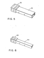
- Figures 5 and 6 show examples of alternative embodiments in which the conventional armature on which the plurality of actuator coils is wound has a cross-section which is other than circular.
- Figure 5 shows one example of a four-sided armature 24C with an actuator coil assembly 28C consisting of four coils shaped to accommodate the four-sided shape of the armature.
- the four-sided shape of armature 24C can be square, rectangular or otherwise, depending upon the needs of the particular application in which it is used.
- Figure 6 shows one example of a three-sided armature 24D with an actuator coil assembly 28D again consisting of four adjacent coils, in this case shaped to accommodate the three-sided shape of the armature.
- the shape of armature 24D is generally triangular, with specific variations such as an equilateral triangle shape, isosceles triangle shape or other three-sided shape again being dependent upon the needs of the particular application..
- the opposing magnetic fields produced by the simultaneously energised coils of the embodiments shown in Figures 5 and 6 include flux build up at the sharp corners of such armatures, the resulting net magnetic field produced by the two coils will still be limited in amplitude, such that the amplitude of the stray magnetic field in the region of the disks and recording heads will be negligible.
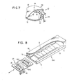
- the planar design uses multiple independent actuators 64 cantilevered on a vertical support 66. Each of these actuators fits between two of a number of disks 14A rotatably mounted on a spindle assembly 16A to provide simultaneous accessing of one surface of each of two adjacent disks.
- the stationary portion of yoke assembly of actuator 64A is constructed from two iron plates 68 and 70 joined in spaced-apart parallel orientation at one end by a vertically disposed plate 72 attached to vertical support 66.
- the spaced-apart parallel orientation of plates 68 and 70 forms an air gap 74 between them.
- the lower of these two plates 70 supports a series of flat magnets 76 of alternating polarity. These magnets produce a high amplitude field within the air gap 74 between plates 68 and 70 which alternates in direction from magnet to magnet.
- Magnetic flux arrows 78 indicate flux direction in the field.
- the armature of the planar actuator assembly is a flat plate 80 slidably mounted within the air gap 74 between iron plates 68 and 70. Mounted on one side of this armature are a plurality of recording heads 82 which address the two surfaces corresponding to the two disks between which the actuator assembly is inserted.
- armature 80 also carries a plurality of pancake coils 84, at least two of which are energised simultaneously to produce opposing fields so that a net field of low amplitude is produced.
- coils 84 are arranged in overlapping pairs 84A and 84B, one pair of which is energised to produce the net field of low amplitude.
- coils 84 could be arranged physically in series, provided they are aligned with corresponding ones of the permanent magnets so that the two energised coils both contribute to useful force.
- the two flat coils comprising coil pair 84A are simultaneously energised with currents flowing in physically opposite directions to produce a net field of low amplitude. Because both coils are on the moving armature 80 of the actuator, they react with the fields from the yoke magnets to contribute usefully to the production of the force and hence acceleration necessary for the recording heads to move and address the surfaces of disks 14A in acceptable periods of time.
- the previously described wiring techniques for conventional actuators may also be used with the flat coils of the embodiment shown in Figures 7 and 8.
- the only requirement is that at least two coils be energised simultaneously and that the physical direction of current flow in the two coils be opposite so that they produce opposing fields that in turn produce a net field which is negligible in amplitude.
Landscapes
- Engineering & Computer Science (AREA)
- Physics & Mathematics (AREA)
- Chemical & Material Sciences (AREA)
- Combustion & Propulsion (AREA)
- Electromagnetism (AREA)
- Power Engineering (AREA)
- Moving Of Heads (AREA)
- Adjustment Of The Magnetic Head Position Track Following On Tapes (AREA)
- Reciprocating, Oscillating Or Vibrating Motors (AREA)
Applications Claiming Priority (2)
| Application Number | Priority Date | Filing Date | Title |
|---|---|---|---|
| US718911 | 1985-04-02 | ||
| US06/718,911 US4669013A (en) | 1985-04-02 | 1985-04-02 | Multiple coils for reduction of stray magnetic fields in disk file actuators |
Publications (2)
| Publication Number | Publication Date |
|---|---|
| EP0197394A2 true EP0197394A2 (fr) | 1986-10-15 |
| EP0197394A3 EP0197394A3 (fr) | 1988-11-02 |
Family
ID=24888060
Family Applications (1)
| Application Number | Title | Priority Date | Filing Date |
|---|---|---|---|
| EP86103855A Withdrawn EP0197394A3 (fr) | 1985-04-02 | 1986-03-21 | Actuateur électromagnétique et mémoire à disque magnétique utilisant celui-ci |
Country Status (4)
| Country | Link |
|---|---|
| US (1) | US4669013A (fr) |
| EP (1) | EP0197394A3 (fr) |
| JP (1) | JPS61229226A (fr) |
| CA (1) | CA1306799C (fr) |
Cited By (4)
| Publication number | Priority date | Publication date | Assignee | Title |
|---|---|---|---|---|
| EP0361670A3 (en) * | 1988-08-31 | 1990-07-11 | Aura Systems, Inc. | Electromagnetic actuator |
| GB2243711A (en) * | 1990-04-13 | 1991-11-06 | Mitsubishi Electric Corp | Flexible disk device |
| EP0522042A4 (fr) * | 1990-03-26 | 1994-01-26 | Aura Systems, Inc. | |
| WO2003069299A3 (fr) * | 2002-02-11 | 2004-03-04 | Ling Dynamic Systems | Actionneur electromagnetique |
Families Citing this family (18)
| Publication number | Priority date | Publication date | Assignee | Title |
|---|---|---|---|---|
| US4868432A (en) * | 1979-12-26 | 1989-09-19 | Unisys Corporation (Formerly Burroughs Corp) | Multi-coil actuator with end cap flux carrier |
| US4808955A (en) * | 1987-10-05 | 1989-02-28 | Bei Electronics, Inc. | Moving coil linear actuator with interleaved magnetic circuits |
| US4831291A (en) * | 1987-10-28 | 1989-05-16 | Kaman Instrumentation Corporation | Differentially wound electromagnetic actuator |
| AU672953B2 (en) * | 1991-08-05 | 1996-10-24 | Speaker Acquisition Sub | Voice coil actuator |
| US5293290A (en) * | 1991-10-17 | 1994-03-08 | Storage Technology Corporation | Stackable linear actuator using embedded coil carriages |
| US5485320A (en) * | 1993-05-24 | 1996-01-16 | Trace Mountain Products, Inc. | Method and apparatus for adjusting asymmetric recording signals |
| JP3387173B2 (ja) * | 1993-10-27 | 2003-03-17 | ソニー株式会社 | 電磁駆動装置 |
| US5521774A (en) * | 1994-03-18 | 1996-05-28 | Cartesian Data, Inc. | Memory storage module for storing and accessing |
| US5539262A (en) * | 1994-08-03 | 1996-07-23 | Aura Systems, Inc. | Axially focused radial magnet voice coil actuator |
| JP3427171B2 (ja) * | 1998-05-01 | 2003-07-14 | 日創電機株式会社 | 成形機 |
| JP3593672B2 (ja) * | 1998-05-01 | 2004-11-24 | 日創電機株式会社 | 成形機 |
| US6278247B1 (en) * | 1999-06-28 | 2001-08-21 | Tristram Tupper Hyde | Multi-resolution drive for actuators |
| US7777600B2 (en) | 2004-05-20 | 2010-08-17 | Powerpath Technologies Llc | Eddy current inductive drive electromechanical liner actuator and switching arrangement |
| US7538980B2 (en) * | 2005-09-14 | 2009-05-26 | International Business Machines Corporation | Actuator assembly |
| US20080042322A1 (en) * | 2006-08-15 | 2008-02-21 | Husky Injection Molding Systems Ltd. | Platen-stroke actuator of molding system, amongst other things |
| US7675202B1 (en) * | 2007-07-18 | 2010-03-09 | Benjamin Huang | Isotropic ring magnet linear voice coil motor |
| US8305714B2 (en) | 2010-12-23 | 2012-11-06 | Hitachi Global Storage Technologies, Netherlands B.V. | Voice-coil motor with voice coils configured oriented in the same direction and substantially overlayed to reduce head vibrations in a disk drive |
| JP6327569B2 (ja) * | 2012-09-12 | 2018-05-23 | メモリアル ユニヴァーシティー オブ ニューファンドランド | 平行運動機構及び平行運動機構のベアリング及びアクチュエータ |
Family Cites Families (6)
| Publication number | Priority date | Publication date | Assignee | Title |
|---|---|---|---|---|
| US3599020A (en) * | 1970-02-27 | 1971-08-10 | Ibm | Linear actuator with alternating magnetic poles |
| US4314295A (en) * | 1979-10-18 | 1982-02-02 | Burroughs Corporation | Linear actuator with staggered flat coils |
| US4612592A (en) * | 1979-12-26 | 1986-09-16 | Burroughs Corporation | Dual coil/dual magnet actuator |
| EP0040509B1 (fr) * | 1980-05-19 | 1986-04-02 | Hugh-Peter Granville Kelly | Moteur linéaire |
| JPH0681482B2 (ja) * | 1982-07-01 | 1994-10-12 | 高橋 義照 | リニアモータ |
| JPS61164459A (ja) * | 1985-01-11 | 1986-07-25 | Showa Electric Wire & Cable Co Ltd | リニアモ−タ |
-
1985
- 1985-04-02 US US06/718,911 patent/US4669013A/en not_active Expired - Fee Related
-
1986
- 1986-02-14 JP JP61029154A patent/JPS61229226A/ja active Granted
- 1986-02-25 CA CA000502703A patent/CA1306799C/fr not_active Expired - Lifetime
- 1986-03-21 EP EP86103855A patent/EP0197394A3/fr not_active Withdrawn
Cited By (6)
| Publication number | Priority date | Publication date | Assignee | Title |
|---|---|---|---|---|
| EP0361670A3 (en) * | 1988-08-31 | 1990-07-11 | Aura Systems, Inc. | Electromagnetic actuator |
| EP0522042A4 (fr) * | 1990-03-26 | 1994-01-26 | Aura Systems, Inc. | |
| GB2243711A (en) * | 1990-04-13 | 1991-11-06 | Mitsubishi Electric Corp | Flexible disk device |
| GB2243711B (en) * | 1990-04-13 | 1994-11-16 | Mitsubishi Electric Corp | Flexible disk device |
| WO2003069299A3 (fr) * | 2002-02-11 | 2004-03-04 | Ling Dynamic Systems | Actionneur electromagnetique |
| US7009477B2 (en) | 2002-02-11 | 2006-03-07 | Lds Test And Measurement Inc. | Electromagnetic actuator |
Also Published As
| Publication number | Publication date |
|---|---|
| US4669013A (en) | 1987-05-26 |
| JPS61229226A (ja) | 1986-10-13 |
| CA1306799C (fr) | 1992-08-25 |
| JPH043593B2 (fr) | 1992-01-23 |
| EP0197394A3 (fr) | 1988-11-02 |
Similar Documents
| Publication | Publication Date | Title |
|---|---|---|
| US4669013A (en) | Multiple coils for reduction of stray magnetic fields in disk file actuators | |
| US4544972A (en) | Swinging actuators for use in magnetic disc type memory devices | |
| EP0031876B1 (fr) | Actionneur électrique à angle de rotation limité | |
| US20020039260A1 (en) | Twin coil positioner | |
| EP0529987B1 (fr) | Appareil de positionnement rotatif | |
| GB1602389A (en) | Device for positioning magnetic heads | |
| US3723779A (en) | Compensated linear motor | |
| US5038062A (en) | Swing-arm type linear d.c. brushless motor | |
| US4396966A (en) | Low mass actuator system for magnetic recording disks with half strength end poles | |
| US5177383A (en) | Voice coil motor | |
| EP0139372A1 (fr) | Assemblage d'actionnement pour dispositif de mémoire | |
| US6606223B2 (en) | Voice coil motor dummy magnet | |
| US5202595A (en) | Yoke member for voice coil motor | |
| US4506307A (en) | Magnetic head slider and actuator assembly | |
| US5420468A (en) | Shorted turn for moving coil motors | |
| JPS5998349A (ja) | デイスク駆動アクチユエ−タ構成体 | |
| JPS63503496A (ja) | 電磁駆動装置 | |
| US5561646A (en) | Focus/tracking actuator with moving-magnet motors | |
| US20030099067A1 (en) | Disc drive head positioned by multiple dipole Halbach motor | |
| JP2700005B2 (ja) | 対物レンズ駆動装置 | |
| EP0113008A1 (fr) | Organe d'entraînement magnétique | |
| JPH04337572A (ja) | ヘッドアクチュエータ | |
| JPS60173727A (ja) | 光学走査装置 | |
| JPH0644582A (ja) | 情報記録再生装置における光学ヘッド駆動装置 | |
| EP0433037B1 (fr) | Moteur axe et unité de disque pourvue de celui-ci |
Legal Events
| Date | Code | Title | Description |
|---|---|---|---|
| PUAI | Public reference made under article 153(3) epc to a published international application that has entered the european phase |
Free format text: ORIGINAL CODE: 0009012 |
|
| AK | Designated contracting states |
Kind code of ref document: A2 Designated state(s): DE FR GB IT |
|
| 17P | Request for examination filed |
Effective date: 19870224 |
|
| PUAL | Search report despatched |
Free format text: ORIGINAL CODE: 0009013 |
|
| AK | Designated contracting states |
Kind code of ref document: A3 Designated state(s): DE FR GB IT |
|
| STAA | Information on the status of an ep patent application or granted ep patent |
Free format text: STATUS: THE APPLICATION HAS BEEN WITHDRAWN |
|
| 18W | Application withdrawn |
Withdrawal date: 19890410 |
|
| RIN1 | Information on inventor provided before grant (corrected) |
Inventor name: WORTHINGTON, THOMAS KIMBER Inventor name: SCRANTON, ROBERT ALAN Inventor name: THOMPSON, DAVID ALLEN |