EP0197446A1 - Procédé pour améliorer la qualité d'image pour des signaux d'images codés par modulation d'impulsions codées - Google Patents
Procédé pour améliorer la qualité d'image pour des signaux d'images codés par modulation d'impulsions codées Download PDFInfo
- Publication number
- EP0197446A1 EP0197446A1 EP86104212A EP86104212A EP0197446A1 EP 0197446 A1 EP0197446 A1 EP 0197446A1 EP 86104212 A EP86104212 A EP 86104212A EP 86104212 A EP86104212 A EP 86104212A EP 0197446 A1 EP0197446 A1 EP 0197446A1
- Authority
- EP
- European Patent Office
- Prior art keywords
- dpcm
- value
- quantization
- values
- image signal
- Prior art date
- Legal status (The legal status is an assumption and is not a legal conclusion. Google has not performed a legal analysis and makes no representation as to the accuracy of the status listed.)
- Withdrawn
Links
- 238000000034 method Methods 0.000 title claims abstract description 20
- 238000013139 quantization Methods 0.000 claims abstract description 61
- 238000012937 correction Methods 0.000 claims abstract description 37
- 230000003111 delayed effect Effects 0.000 claims 1
- 238000010586 diagram Methods 0.000 description 6
- 230000005540 biological transmission Effects 0.000 description 5
- 238000001514 detection method Methods 0.000 description 5
- 230000015654 memory Effects 0.000 description 5
- 239000008186 active pharmaceutical agent Substances 0.000 description 3
- 238000004364 calculation method Methods 0.000 description 3
- 230000007547 defect Effects 0.000 description 1
- 238000013461 design Methods 0.000 description 1
- 238000011161 development Methods 0.000 description 1
- 230000018109 developmental process Effects 0.000 description 1
- 230000009365 direct transmission Effects 0.000 description 1
- 230000000694 effects Effects 0.000 description 1
- 238000003780 insertion Methods 0.000 description 1
- 230000037431 insertion Effects 0.000 description 1
- 230000001788 irregular Effects 0.000 description 1
- 238000012545 processing Methods 0.000 description 1
- 238000011144 upstream manufacturing Methods 0.000 description 1
Images


Classifications
-
- H—ELECTRICITY
- H04—ELECTRIC COMMUNICATION TECHNIQUE
- H04N—PICTORIAL COMMUNICATION, e.g. TELEVISION
- H04N19/00—Methods or arrangements for coding, decoding, compressing or decompressing digital video signals
- H04N19/90—Methods or arrangements for coding, decoding, compressing or decompressing digital video signals using coding techniques not provided for in groups H04N19/10-H04N19/85, e.g. fractals
-
- H—ELECTRICITY
- H04—ELECTRIC COMMUNICATION TECHNIQUE
- H04N—PICTORIAL COMMUNICATION, e.g. TELEVISION
- H04N19/00—Methods or arrangements for coding, decoding, compressing or decompressing digital video signals
- H04N19/10—Methods or arrangements for coding, decoding, compressing or decompressing digital video signals using adaptive coding
- H04N19/102—Methods or arrangements for coding, decoding, compressing or decompressing digital video signals using adaptive coding characterised by the element, parameter or selection affected or controlled by the adaptive coding
- H04N19/124—Quantisation
-
- H—ELECTRICITY
- H04—ELECTRIC COMMUNICATION TECHNIQUE
- H04N—PICTORIAL COMMUNICATION, e.g. TELEVISION
- H04N19/00—Methods or arrangements for coding, decoding, compressing or decompressing digital video signals
- H04N19/50—Methods or arrangements for coding, decoding, compressing or decompressing digital video signals using predictive coding
Definitions
- the invention relates to a method for improving the image quality, in which digitized image signal values are converted into quantized DPCM values using a multidimensional, in particular a two-dimensional, prediction and switchable quantization characteristics.
- DPCM Differential pulse code modulation
- the most common is the two-dimensional DPCM, in which an estimate or prediction value is calculated from image signal values that adjoin the current image signal value to be processed.
- DPCM coding with two-dimensional prediction is already surprisingly powerful.
- a switch is made between several quantization characteristics, so that the quantization takes place in small quantization steps when there are small differences between the estimated value and the current image signal value; for large differences, such as those occurring at edges, a coarser quantization is used, but the quantization error is largely invisible to the human eye due to the covering effect.
- the two-dimensional quantization also for edges - does astonishing things, there are clearly visible image defects at the corners of geometric surfaces, such as those often found in buildings or typefaces.
- the object of the invention is to improve the image quality with two-dimensional DPCM coding.
- the object is achieved in that when the maximum values of a quantization characteristic are exceeded by the current DPCM value, a correction signal is transmitted and the next reconstructed image signal value is determined both on the transmission side and on the reception side with the aid of the same correction value.
- the invention is based on the knowledge that image errors are caused by the use of the unsuitable quantization characteristic.
- the switchover criterion for the transmitter-side quantizer and for the corresponding receiver-side decoding device can only take place with the aid of the reconstructed image signal values, since the synchronism between the encoder and decoder must not be disturbed.
- the decoder naturally fails to take a look into the future, the coder, which uses the same control logic but notices incorrect control of the quantizer in good time, corrects its error and communicates this to the decoder via the correction signal, the same correction value being fed into the calculation loop. This procedure means that critical image signal errors on edges no longer appear to be disturbing and the synchronism between encoder and decoder is not disturbed.
- a password and a PCM correction value are transmitted as the correction signal, and it is also expedient that the PCM correction value is transmitted quantized.
- the corresponding PCM image signal value is transmitted and used for the calculation of the further estimated values both on the transmission side and on the reception side. It is sufficient that this PCM value is also transmitted quantized.
- the system switches over to the coarsest quantization characteristic. Depending on the quantization characteristics used, this switchover can also be limited to the coarsest from the finest quantization characteristic or the two finest quantization characteristics.
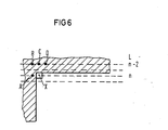
- FIG. 6 shows a section of a television picture using television field transmission.
- the pixels A to D and X of a television field of television lines L n-2 and n are shown.
- the calculation of the estimated value is therefore carried out with the aid of the image signal values A, B, C and D surrounding the current image signal value X, which correspond to the sample values. It is assumed that the luminance signal is to be encoded and transmitted here. The same applies analogously to color difference signals.
- the hatched area in which the image signal values A to D lie corresponds to the image signal value zero, that is to say black, and the next image signal value X corresponds to the maximum image signal value, here the numerical value 255, that is to say white.
- the following estimated value ⁇ is determined from the image signal values X r , C " D r and Er.
- the quantizer is controlled by forming the differences between the reconstructed image signal values A t to D,.
- the maximum difference DS determines the quantization characteristic QK1 to QK4 to be used.
- the following table shows the ranges of 4 different quantization characteristics QK1 to QK4 and their assignment to the different differences DS.
- An additional quantization characteristic QK5 can be useful when transmitting correction values.
- Estimated value X 'and the following image signal value X reach the maximum of 255.
- the difference between that "Incorrectly coded" transmitted DPCM value of size 55 and the correct DPCM value of 255 naturally cause visible disturbances in corners in picture templates.
- FIG. 1 shows the basic circuit diagram of a DPCM encoder for implementing the method according to the invention.
- Digitized sample values (luminance or chrominance values), here referred to as image signal values s, are supplied to the code input 1.
- the code input is connected to the first input of a subtractor 2, the output of which is connected to the input of a controllable quantizer 3.
- the output of the quantizer 3 is connected via a first adder 6 and a first switch 8 to an input 41 of a quantizer control logic 4 and the input of a predictor 5.
- the output of the predictor 5 is connected to the second input of the adder 6 and to the subtraction input of the subtractor 2.
- Another input 42 of the quantizer control logic is connected to the output of the subtractor 2.
- a first control output 43 of the quantizer control logic is connected to a control input 31 of the quantizer 3.
- a encoder 7 is connected to the output of the quantizer, the output of which is connected to the first input of a second changeover switch 9.
- the second input of this switch like the second input of the first switch 8, is directly connected to the code input 1.
- the output of the second switch 9 forms the output 10 of the encoder.
- the two changeover switches 8 and 9 are actuated via a second control output 44 of the quantizer control logic 4. This control input also intervenes in the encoder 7.
- the encoder shown works in the usual way.
- the estimate 9 is determined, this is subtracted from the current image signal value s in the subtractor 2 and the DPCM value As is fed to the quantizer 3, the quantization characteristic of which is determined by the quantization control logic 4.
- the quantized DPCM values ⁇ s q present at the output of the quantizer 3 are fed to the encoder 7, which assigns a binary combination to each quantization stage for data reduction. If, for example, 15-stage quantization characteristics QK1 to QK4 are used, the binary combination 0000 to 1110 is used.
- the decoder input 11 is connected to a decoding device 37, a detection circuit 12 and a second input of a changeover switch 19.
- the output of the decoder 37 is connected via a second adder 16 to the first input of the switch 19, the output of which is connected to the input of a decoder control logic 14 corresponding to the quantizer control logic and a predictor 15 at the receiving end.
- the output of the predictor 15 on the receiving side is connected to the second input of the second adder 16.
- the control output of the detection circuit 12 is connected to the control input of the switch 19.
- the image signal values s r are reconstructed in the usual way from the DPCM values ⁇ s c applied to the decoder input 11.
- the decoding device 37 corresponds to the counterpart on the receiving side for the series connection of the controllable quantizer 3 and encoder 7. From the coded DPCM values ⁇ s c , the quantized DPCM values ⁇ s q with the required word width are recovered. If the detection circuit 12 notices the receipt of an identification word KW, the changeover switch 19 is actuated by the received correction signal EKS and the subsequent PCM image signal value s is switched through to the decoder output 20 and thus simultaneously to the decoder control logic 14 and the predictor 15 on the reception side.
- the insertion of the correction signal KS consisting of the code word KW and the PCM image signal value s, causes an irregular data flow.
- the clock control of the decoder control logic and the receiving-side predictor is changed during the reception of a correction signal.
- both the decoder control logic and the receiver-side predictor are supplied with the PCM image signal value transmitted in the correction signal.
- a continuous data flow is again achieved by means of an elastic memory.
- a clock control on the receiving side ensures correct processing.
- a further changeover switch 18 is connected upstream of the input of the controllable quantizer 3, via which the quantizer input can be connected directly to the code input 1 or, as usual, to the output of the subtractor 2.
- the second switch 9 is omitted and, in contrast to the DPCM encoder according to FIG. 1, the second input of the first switch 8 is connected to the output of the quantizer 3 instead of to the code input 1.
- the further changeover switch 18, like the first changeover switch 8, is actuated by the quantizer control logic 4.
- the DPCM decoder corresponding to FIG. 3 differs from the DPCM decoder shown in FIG. 2 only in that the second input of the third switch 19 is connected to the output of the decoding device 37.
- the DPCM coder shown in FIG. 4 differs from the DPCM coder shown in FIG. 3 solely in the absence of the changeover switches 18 and 8.
- the image signal values s r are fed to the quantizer control logic 4.
- Control outputs 43, 44 of the quantizer control logic lead to the controllable quantizer 3 and the encoder 7.
- the identification word is first inserted via the encoder 7. Subsequently, however, a DPCM value is sent out instead of the existing PCM image signal value. Since the transmission of DPCM values of the extent of the finest quantization characteristic (possibly several quantization characteristics) can also be dispensed with here, it is possible to use larger QC5 values (or further quantization characteristics) than otherwise possible using an additional quantization characteristic QK5. to transmit with sufficient quantization accuracy. As usual, the encoder assigns binary combinations to the different stages of the additional quantization characteristic QK5.
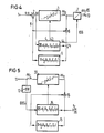
- the DPCM decoder shown in FIG. 5 differs from the DPCM decoder shown in FIG. 2 in that there is no switch 19; the inputs of the quantization control logic 14 on the receiving side and of the predictor 15 are directly connected to the output of the adder 16.
- the output of the detection circuit 12 is likewise connected to the decoder control logic 14 and, after receiving an identification word, switches off to the roughest of the usual or to an additional quantization characteristic.
- Another variant of this method consists in delaying the image signal values output at the decoder output and replacing critical image signal values with a correction value which is obtained from adjacent image signal values received later, e.g. is determined from a subsequent image signal value and from the corresponding image signal values of the following image line.
Landscapes
- Engineering & Computer Science (AREA)
- Multimedia (AREA)
- Signal Processing (AREA)
- Compression, Expansion, Code Conversion, And Decoders (AREA)
- Compression Or Coding Systems Of Tv Signals (AREA)
Applications Claiming Priority (2)
| Application Number | Priority Date | Filing Date | Title |
|---|---|---|---|
| DE19853511660 DE3511660A1 (de) | 1985-03-29 | 1985-03-29 | Verfahren zur verbesserung der bildqualitaet bei dpcm-codierten bildsignalen |
| DE3511660 | 1985-03-29 |
Publications (1)
| Publication Number | Publication Date |
|---|---|
| EP0197446A1 true EP0197446A1 (fr) | 1986-10-15 |
Family
ID=6266851
Family Applications (1)
| Application Number | Title | Priority Date | Filing Date |
|---|---|---|---|
| EP86104212A Withdrawn EP0197446A1 (fr) | 1985-03-29 | 1986-03-26 | Procédé pour améliorer la qualité d'image pour des signaux d'images codés par modulation d'impulsions codées |
Country Status (2)
| Country | Link |
|---|---|
| EP (1) | EP0197446A1 (fr) |
| DE (1) | DE3511660A1 (fr) |
Cited By (4)
| Publication number | Priority date | Publication date | Assignee | Title |
|---|---|---|---|---|
| EP0414193A3 (en) * | 1989-08-21 | 1991-12-27 | Mitsubishi Denki Kabushiki Kaisha | Adaptive quantization coder/decoder |
| EP0547826A1 (fr) * | 1991-12-18 | 1993-06-23 | Raytheon Company | Compresseur ADPCH (MICDA) à nombre de bits adaptatif pour des données d'images |
| EP0444839A3 (fr) * | 1990-02-26 | 1994-02-09 | Sony Corp | |
| US6109665A (en) * | 1995-12-21 | 2000-08-29 | Metu-System Meining Kg | Butt joint of air duct sections |
Families Citing this family (3)
| Publication number | Priority date | Publication date | Assignee | Title |
|---|---|---|---|---|
| DE3812665A1 (de) * | 1988-04-15 | 1989-10-26 | Siemens Ag | Verfahren zur uebertragung von videosignalen |
| JP2892783B2 (ja) * | 1990-07-09 | 1999-05-17 | 松下電器産業株式会社 | 動画像信号の符号化装置 |
| JPH0474063A (ja) * | 1990-07-13 | 1992-03-09 | Matsushita Electric Ind Co Ltd | 画像の符号化方法 |
Citations (4)
| Publication number | Priority date | Publication date | Assignee | Title |
|---|---|---|---|---|
| US3403226A (en) * | 1965-09-30 | 1968-09-24 | Bell Telephone Labor Inc | Reduced bandwidth dual mode encoding of video signals |
| US3422227A (en) * | 1965-09-30 | 1969-01-14 | Bell Telephone Labor Inc | Dual code differential encoding scheme for video signals |
| US3761613A (en) * | 1972-06-20 | 1973-09-25 | Bell Telephone Labor Inc | Dual mode video encoder |
| US4217609A (en) * | 1978-02-28 | 1980-08-12 | Kokusai Denshin Denwa Kabushiki Kaisha | Adaptive predictive coding system for television signals |
-
1985
- 1985-03-29 DE DE19853511660 patent/DE3511660A1/de not_active Withdrawn
-
1986
- 1986-03-26 EP EP86104212A patent/EP0197446A1/fr not_active Withdrawn
Patent Citations (4)
| Publication number | Priority date | Publication date | Assignee | Title |
|---|---|---|---|---|
| US3403226A (en) * | 1965-09-30 | 1968-09-24 | Bell Telephone Labor Inc | Reduced bandwidth dual mode encoding of video signals |
| US3422227A (en) * | 1965-09-30 | 1969-01-14 | Bell Telephone Labor Inc | Dual code differential encoding scheme for video signals |
| US3761613A (en) * | 1972-06-20 | 1973-09-25 | Bell Telephone Labor Inc | Dual mode video encoder |
| US4217609A (en) * | 1978-02-28 | 1980-08-12 | Kokusai Denshin Denwa Kabushiki Kaisha | Adaptive predictive coding system for television signals |
Non-Patent Citations (3)
| Title |
|---|
| FUNKSCHAU, Band 45, Nr. 16, August 1973, Seiten 591-593, München, DE; H. SCHÖNFELDER: "Nachrichtenreduktion für Bildsignale" * |
| IEEE TRANSACTIONS ON COMMUNICATIONS, Band COM-15, Nr. 2, April 1967, Seiten 204-208, IEEE, New York, US; F.K. MANASSE: "Directional correlation - A technique to reduce bandwidth in PCM television transmissions" * |
| RADIO MENTOR ELECTRONIC, Band 38, Nr. 10, Oktober 1972, Seiten 489-490, München, DE; H.-G. GIESE et al.: "Ein Redundanzreduktionsverfahren für digitale Fernsehübertragungen" * |
Cited By (7)
| Publication number | Priority date | Publication date | Assignee | Title |
|---|---|---|---|---|
| EP0414193A3 (en) * | 1989-08-21 | 1991-12-27 | Mitsubishi Denki Kabushiki Kaisha | Adaptive quantization coder/decoder |
| EP0444839A3 (fr) * | 1990-02-26 | 1994-02-09 | Sony Corp | |
| EP0739143A3 (fr) * | 1990-02-26 | 1996-12-18 | Sony Corp | Méthode et dispositif pour coder un signal vidéo |
| EP0739142A3 (fr) * | 1990-02-26 | 1996-12-18 | Sony Corp | Méthode et dispositif pour coder un signal vidéo |
| KR100248692B1 (ko) * | 1990-02-26 | 2000-03-15 | 이데이 노부유끼 | 비디오 신호 코딩 시스템과 비디오 신호 코딩 방법 |
| EP0547826A1 (fr) * | 1991-12-18 | 1993-06-23 | Raytheon Company | Compresseur ADPCH (MICDA) à nombre de bits adaptatif pour des données d'images |
| US6109665A (en) * | 1995-12-21 | 2000-08-29 | Metu-System Meining Kg | Butt joint of air duct sections |
Also Published As
| Publication number | Publication date |
|---|---|
| DE3511660A1 (de) | 1986-10-02 |
Similar Documents
| Publication | Publication Date | Title |
|---|---|---|
| DE69525009T2 (de) | Verfahren zur differentiellen Kodierung von Bewegungsvektoren mit Mittelwertprädiktion | |
| DE69620984T2 (de) | Geräuschschätzungs- und Geräuschreduzierungsgerät zur Videosignalverarbeitung | |
| DE69225941T2 (de) | Bildkodierung und/oder -dekodierung | |
| DE69525733T2 (de) | Vorrichtung zur Kodierung/Dekodierung eines Bildsignals mit einem gleichbleibenden Objekt | |
| DE69031145T2 (de) | Video-Übertragungssystem mit einer adaptiven Bild-zu-Bild-Prädiktionscodierung | |
| DE3213298C2 (de) | Schaltungsanordnung zum Mischen zweier Farbvideosignale durch Farbstanzen | |
| DE69301297T2 (de) | Verfahren zur Fehlerverdeckung für die Übertragung von MPEG-kodierten Bildern | |
| DE3331426A1 (de) | Anordnung zur zweidimensionalen dpcm-codierung | |
| DE3319438C2 (fr) | ||
| DE3311911A1 (de) | Verfahren und schaltungsanordnung zur bildfehlerkorrektur | |
| DE69321924T2 (de) | Verfahren zum zwei-standard-kodieren von bildern, mit sehr niedriger datenrate und codierer/decodierer zur durchführung dieses verfahrens | |
| DE3426939C2 (de) | Vorrichtung für eine geschlossene prädiktive Quantisierung eines digitalen Vektorsignals | |
| DE3889939T2 (de) | Verfahren und Mittel zur Kodierung und Dekodierung eines Bildsignals. | |
| DE69026143T2 (de) | Kodefehler korrigierende Vorhersage-Decodiervorrichtung | |
| DE19717608B4 (de) | Wahrnehmungsfehlerbearbeitungsverfahren und Bildkodierungsvorrichtung, welche dieses Verfahren verwendet | |
| EP0197446A1 (fr) | Procédé pour améliorer la qualité d'image pour des signaux d'images codés par modulation d'impulsions codées | |
| EP0346637B1 (fr) | Procédé pour le traitement et la transmission d'une séquence d'images | |
| DE69418538T2 (de) | Kodierung von analogen Bildsignalen | |
| EP0414017A2 (fr) | Procédé de compensation du mouvement orienté d'objet d'information d'image pour la reproduction de sequences d'images animées codées | |
| DE19643907B4 (de) | Verfahren und Vorrichtung zur Bewegtbildkodierung | |
| DE3311898C2 (de) | Verfahren zur Störsignalreduktion von digitalen datenreduzierten Fernsehsignalen | |
| DE2703854C2 (de) | Bildübertragungsanlage | |
| DE3726601C2 (fr) | ||
| DE2364629A1 (de) | System zur codierung von video-signalen nach dem sogenannten differenzsignalverfahren | |
| EP0244001A2 (fr) | Codeur hybride pour des signaux vidéo |
Legal Events
| Date | Code | Title | Description |
|---|---|---|---|
| PUAI | Public reference made under article 153(3) epc to a published international application that has entered the european phase |
Free format text: ORIGINAL CODE: 0009012 |
|
| AK | Designated contracting states |
Kind code of ref document: A1 Designated state(s): AT BE CH DE FR GB IT LI NL SE |
|
| 17P | Request for examination filed |
Effective date: 19861106 |
|
| 17Q | First examination report despatched |
Effective date: 19880726 |
|
| STAA | Information on the status of an ep patent application or granted ep patent |
Free format text: STATUS: THE APPLICATION IS DEEMED TO BE WITHDRAWN |
|
| 18D | Application deemed to be withdrawn |
Effective date: 19881206 |
|
| RIN1 | Information on inventor provided before grant (corrected) |
Inventor name: GRALLERT, HANS-JOACHIM, DR. ING. |