EP0197459A2 - Soupape à diaphragme - Google Patents
Soupape à diaphragme Download PDFInfo
- Publication number
- EP0197459A2 EP0197459A2 EP86104291A EP86104291A EP0197459A2 EP 0197459 A2 EP0197459 A2 EP 0197459A2 EP 86104291 A EP86104291 A EP 86104291A EP 86104291 A EP86104291 A EP 86104291A EP 0197459 A2 EP0197459 A2 EP 0197459A2
- Authority
- EP
- European Patent Office
- Prior art keywords
- elongated
- diaphragm
- elongated member
- chamber
- valve
- Prior art date
- Legal status (The legal status is an assumption and is not a legal conclusion. Google has not performed a legal analysis and makes no representation as to the accuracy of the status listed.)
- Withdrawn
Links
- 238000004891 communication Methods 0.000 claims description 9
- 239000007789 gas Substances 0.000 description 13
- 238000007789 sealing Methods 0.000 description 3
- 230000000694 effects Effects 0.000 description 2
- 239000000463 material Substances 0.000 description 2
- 229910000831 Steel Inorganic materials 0.000 description 1
- 238000006243 chemical reaction Methods 0.000 description 1
- 238000010276 construction Methods 0.000 description 1
- 238000002788 crimping Methods 0.000 description 1
- 230000000994 depressogenic effect Effects 0.000 description 1
- 230000008030 elimination Effects 0.000 description 1
- 238000003379 elimination reaction Methods 0.000 description 1
- 239000012530 fluid Substances 0.000 description 1
- 239000002991 molded plastic Substances 0.000 description 1
- 238000000465 moulding Methods 0.000 description 1
- 239000004033 plastic Substances 0.000 description 1
- 230000000284 resting effect Effects 0.000 description 1
- 239000010959 steel Substances 0.000 description 1
Images

Classifications
-
- F—MECHANICAL ENGINEERING; LIGHTING; HEATING; WEAPONS; BLASTING
- F16—ENGINEERING ELEMENTS AND UNITS; GENERAL MEASURES FOR PRODUCING AND MAINTAINING EFFECTIVE FUNCTIONING OF MACHINES OR INSTALLATIONS; THERMAL INSULATION IN GENERAL
- F16K—VALVES; TAPS; COCKS; ACTUATING-FLOATS; DEVICES FOR VENTING OR AERATING
- F16K7/00—Diaphragm valves or cut-off apparatus, e.g. with a member deformed, but not moved bodily, to close the passage ; Pinch valves
- F16K7/12—Diaphragm valves or cut-off apparatus, e.g. with a member deformed, but not moved bodily, to close the passage ; Pinch valves with flat, dished, or bowl-shaped diaphragm
- F16K7/14—Diaphragm valves or cut-off apparatus, e.g. with a member deformed, but not moved bodily, to close the passage ; Pinch valves with flat, dished, or bowl-shaped diaphragm arranged to be deformed against a flat seat
- F16K7/16—Diaphragm valves or cut-off apparatus, e.g. with a member deformed, but not moved bodily, to close the passage ; Pinch valves with flat, dished, or bowl-shaped diaphragm arranged to be deformed against a flat seat the diaphragm being mechanically actuated, e.g. by screw-spindle or cam
Definitions
- the invention relates to diaphragm valves, particularly for containers for pressurized gas.
- the invention involves a diaphragm valve for containers, such as, cylinders, for pressurized gas.
- the diaphragm valve has an elongated member body having an elongated central passageway, and a flexible diaphragm positioned in and sealingly affixed to the sides of the elongated central passageway of the elongated body member.
- the diaphragm forms a first chamber and a second chamber in the elongated central passageway of the elongated body member.
- the plane of the diaphragm is approximately perpendicular to the longitudinal axis of the elongated central passageway of the elongated body member.
- a valve stem is rotatably positioned in the first chamber in a manner whereby the valve stem can be moved toward or away from the diaphragm.
- the first end of the valve stem protrudes out of the first chamber.
- Means for rotating the valve stem is affixed on the first end of the valve stem.
- a second elongated member, having a central passageway is positioned in the second chamber of the first elongated member.
- the second end of the second elongated member is sealingly affixed to the second end opening of the first elongated member.
- the first end of the second elongated member forms a valve seat.
- the valve seat is positioned near but not in contact with the diaphragm.
- the end of the first elongated member corresponds to the second end port of the first elongated member and is adapted to be sealingly affixed to a container for compressed gas.
- the secdnd end of the valve stem is positioned in the central chamber of the cup member.
- the second end of the valve stem contacts, or is capable of contacting, the flat bottom portion of the cup member.
- the diaphragm valve is capable of being moved into a closed position by rotating the valve stem inwardly, thereby the flat bottom portion of the cup member sealingly presses the diaphragm against the valve seat of the second elongated member and whereby the route of communication is sealingly interrupted.
- the elongated member is a tube, and the valve seat is formed by the first end of the elongated member having been outwardly rolled over.
- the elongated body member is a tube.
- the elongated body member is preferably composed of a first tube member and a second tube member joined together.
- the diaphragm is sealingly affixed around its rim by means of the joint between the first tube member and the second tube member.
- valve stem has a longitudinal passageway and a rotatable shaft being located in the longitudinal passageway.
- a flat ring is preferably mounted around the lower end of the shaft. The bottom of the flat ring contacts the top of the flat bottom of the cup-shaped member and the top of the flat ring contacting the bottom surface of the lower end of the valve stem.
- a rim is positioned inside of the central passageway of the second elongated member.
- the rim has a central passageway.
- the rim is positioned near the first end of the second elongated member.
- the first end of a coil spring contacts the diaphragm.
- the portion of the coil spring near the second end of the coil spring is positioned in the portion of the central passageway of the second elongated member corresponding to the first end of the first elongated member.
- the second end of the coil spring contacts the rim.
- the coil spring normally holds the diaphragm in the open position.
- the spring is of sufficient load to assure that the diaphragm does not seal off the container prior to reaching the desired vacuum in the cylinder, when the valve is in the open position. In the closed position, sufficient torque for closing must be applied to overcome the spring load and apply sufficient sealing load.
- the invention involves, in combination, a container for pressurized gas and a diaphragm valve, said container having a port in the wall thereof.
- the diaphragm valve has an elongated member body having an elongated central passageway, and a flexible diaphragm positioned in and sealingly affixed to the sides of the elongated central passageway of the elongated body member.
- the second end opening of the elongated member is axially aligned with the port of the container.
- the diameter of the central passageway of the elongated central passageway is greater than the diameter of the port of the container.
- the second end of the elongated member is an outwardly extending surface which is sealingly affixed to the outside surface of the wall of the container around the port of the container.
- the diaphragm forms a first chamber and a second chamber in the elongated central passageway of the elongated body member.
- the plane of the diaphragm is approximately perpendicular to the longitudinal axis of the elongated central passageway of the elongated body member.
- a valve stem is rotatably positioned in the first chamber in a manner whereby the valve stem can be moved toward or away from the diaphragm.
- the first end of the valve stem protrudes out of the first chamber.
- Means for rotating the valve stem is affixed on the first end of the valve stem.
- a port located in the side of the elongated member which communicates with the second chamber of the elongated member.
- a short member having a central passageway, which has its first end affixed in the port. The second end of the short member is adapted to be connected to a.source of pressurized gas.
- a second elongated member having a central passageway is positioned in the second chamber of the first elongated member. The second end of the second elongated member extends through the port of the container.
- the second end of the second elongated member is an outward extending surface which is sealingly affixed to the inside of the wall of the container around the port of the container.
- the first end of the second elongated member forms a valve seat.
- the valve seat is positioned near but not in contact with the diaphragm.
- the end of the first elongated member corresponds to the second end port of the first elongated member and is adapted to be sealingly affixed to a container for compressed gas.
- the cup member is positioned in the first chamber of the first elongated member.
- the bottom portion cup member contacts or is capable of contacting, the diaphragm.
- the second end of the valve stem is positioned in the central chamber of the cup member.
- the second end of the valve stem contacts, or is capable of contacting, the flat bottom portion of the cup member.
- the diaphragm valve is capable of being moved into a closed position by rotating the valve stem inwardly, whereby the flat bottom portion of the cup member sealingly presses the diaphragm against the valve seat of the second elongated member and thereby the route of communication is sealingly interrupted.
- a diaphragm valve and a rim is positioned inside of the central passageway of the second elongated member.
- the rim has a central passageway.
- the rim is positioned near the first end of the second elongated member.
- the first end of a coil spring contacts the diaphragm.
- the portion of the coil spring near the second end of the coil spring is positioned in the portion of the central passageway of the second elongated member corresponding to the first end of the second elongated member.
- the second end of the coil spring contacts the rim.
- the coil spring normally holds the diaphragm in the open position.
- the elongated member is a tube
- the valve seat is formed by the first end of the elongated member having been outwardly rolled over.
- the elongated body member is a tube.
- the elongated body member is preferably composed of a first tube member and a second tube member joined together.
- the diaphragm is sealingly affixed around its rim by means of the joint between the first tube member and the second tube member.
- the valve stem has a longitudinal passageway, and a rotatable shaft is located in the longitudinal passageway.
- a flat ring is preferably mounted around the lower end of the shaft. The bottom of the flat ring contacts the top of the flat bottom of the cup-shaped member and the top of the flat ring contacting the bottom surface of the lower end of the valve stem.
- diaphragm valve 10 is fixedly mounted in entrance port 12 of cylinder 14 (partially shown).
- Valve 10 has outer tube member 16 composed of lower tube segment 18 and upper tube segment 20.
- Outer tube member 16 can have any shaped cross-section, but a circular cross-section is preferred.
- Lower edge 22 of upper tube segment 20 is a flat, outwardly extending rim.
- Upper edge 24 of lower tube segment 18 is an inwardly-facing, outwardly-extending U-shaped portion.
- the rim of diaphragm 26 fits in and tightly against the U-shaped upper edge 24.
- Lower rim 22 fits on top of the edge portion of diaphragm 26 and in U-shaped upper edge 24.
- U-shaped upper edge 24 has been crimped so as to tightly hold diaphragm 26 and upper tube segment 20 in place and to seal the rim of diaphragm 26 in reaction to the interior portion - (chamber 28) of lower tube segment 18.
- valve stem 32 Most of the lower portion of valve stem 32 is positioned inside (chamber 34) of upper tube portion 20. About the upper half of the inside wall surface of upper tube portion 20 is internally threaded 36. Cup 38 is positioned in chamber 34 with its open end facing upward and its flat bottom 40 in contact with the top surface of diaphragm 26.
- Valve stem 32 has main stem 42, handle 44 connected to the top of main stem 42 and externally-threaded sleeve 46'mounted around the middle portion of main stem 42. Externally-threaded sleeve 46 is threadingly engaged with internally-threaded portion 36 of upper tube portion 20.
- Main stem 42 and handle 44 contain vertical passageway 48, which has a circular cross-section. Cylindrical shaft 50 slidably fits within passageway 48.
- Cylindrical ring 52 is affixedly mounted on the lower end of cylindrical shaft 50 which extends below the end of main shaft 42.
- the bottom side of cylindrical ring 52 is flat and contacts the inside surface of bottom 40 of cup 38.
- Shaft 50 and ring 52 are preferably constructed as one piece.
- Diaphragm 26 is held taut enough and has strength not to be appreciably depressed by the weight of cup 38, center shaft 50 and ring 52.
- Upper edge 78 is inwardly crimped to prevent removal of valve stem 32 from chamber 34.
- Spud 54 is an elongated member having longitudinal central bore 56. Spud 54 is externally threaded (58) in its middle portion. Both end rims - (60, 62) of spud 54 are outwardly slanted. Bevelled rim 60 of spud 54 is mounted in circular port 64 located in the upper wall region of lower tube segment 18. Port 62 is slightly smaller in diameter than circular bevelled rim 60. Projection weld 66 holds spud 54 in place and helps seal the interface of bevelled rim 60 and the outer edge of port 64. External threads 58 allow a source of compressed gas (not shown) to be attached to spud 54 in order to deliver compressed gas to cylinder 14.
- Inner tube member 68 is positioned within chamber 28 of lower tube segment 18. Upper edge 70 of inner tube member 68 is outwardly flaired out and over to form a rounded valve seat for diaphragm 26. Inner tube member 68 has inner passageway 72. The lower end of inner tube member extends through port 12 of cylinder and forms lip 74. Lip 74 is an outwardly-extending essentially-flat portion which mates with the inside surface of slightly inwardly-curved top portion of cylinder 14. Lower lip 30 of lower tube segment 18 is an outwardly-extending essentially-flat portion which mates with the outside surface of the slightly- curved top portion of cylinder 14. Double projection weld 76 is used to fixedly attach lower lip 30 and lower lip 30 to cylinder 14 in a sealed manner.
- Internal rim 80 (with internal passageway 82) is located on the outside surface of inner tube member 68 slightly below edge 70. Also, edge 70 of inner tube member 68 is located close to, but does not contact, the bottom surface of diaphragm 26 - (when diaphragm 26 is in its normal or open position).
- Coil spring 84 is positioned in the upper end of inner tube 68, resting on rim 80 and contacting diaphragm 26. Flexible diaphragm 26 is mounted above valve seat 70 and must be forced downward out of its normal horizontal orientation against the valve seat by turning valve stem 42 so as to rotate downwardly in order to effect closure. Diaphragm valve 10 does not require spring 84 to maintain diaphragm 26 in the open position, except in some instances when a vacuum has been pulled on the interior of gas cylinder 14.
- the diaphragm valve of the invention has a broad scope of usage, but is specifically intended for use on cylinders for shipment of compressed gases.
- the design and construction of diaphragm valve 10 provides improved features at substantial reduced costs.
- the operation of diaphragm valve 10 allows fluid to enter or exit through the port 56, which communicates with chamber 28 between valve body 18 and valve seat body 68 which in turn communicates with cylinder 14 via chamber 72 of valve seat body 68.
- Spring 84 is positioned in the top portion of center passageway 72 of valve seat body 68, with its bottom portion seated on rim 80 inside of central passageway 72 of valve seat body 68 and with its top rim pressing against diaphragm 26.
- a vacuum can be drawn on cylinder 14 so as to be filled with load (strength) to assure diaphragm 26 does not seal off cylinder 14 prior to reaching the desired vacuum in cylinder 14 when valve 10 is in the open position.
- load stress
- diaphragm 26 does not seal off cylinder 14 prior to reaching the desired vacuum in cylinder 14 when valve 10 is in the open position.
- load stress
- stem 36 is turned to overcome spring 84 and to 'cause flexible diaphragm 26 to become sealed on valve seat 70.
- Such action causes communication from port 56 in spud 54 and chamber 28 between valve body 18 and valve seat body 68 to be sealed off from the interior of cylinder 14.
- the invention diaphragm valve preferably uses projection welds and a crimping operation. Spud 54 can be produced as a screw machine part.
- Lower tube segment 18 has an internal diameter of 1 1/4 inches and a height of 2 1/2 inches from its bottom to the location of diaphragm 26.
- Diaphragm 26, for example has a diameter of 1 5/8 inches and a thickness of diaphragm 26 preferably is composed of flexible, neoprenew rubber.
- Diaphragm 26 is a simple die- cut diaphragm.
- U-shaped upper edge 24, for example, has a thickness of 1/8 inch.
- Upper tube segment 20, for example has an internal diameter of 1 1/8 inches and a height of about 2 inches from its bottom to the top of its crimped portion 7-8.
- Upper tube segment 20, lower tube segment 18, cup 38, and inner tube member 68 are preferably composed of a steel which can readily be produced with high-speed drawing equipment (for minimum use of labor and material).
- Stem handle 44 can be a molded plastic part which is designed for ease of molding and use of low cost plastic material.
- Inner tube member 68 for example, has an internal diameter of 1/8 inch and a height of about 2 1/4 inches.
- Cup 38 for example, has an internal diameter of 7/8 inches and a height of 1 1/4 inches.
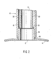
- FIG. 2 another attachment mode which is shown is diaphragm valve 10 to cylinder 14.
- Lower tube segment 18 of diaphragm valve 10 is internally threaded.
- Externally threaded short nozzle 86 is projection welded (88) into port 12 of cylinder 14.
- the bottom portion of lower tube segment 18 is threaded on to externally threaded nozzle 86.
- Inner tube member 68 is positioned inside of lower tube segment 18 so as to form outer chamber 28 and inner chamber 72.
- the lower edge of inner tube member 68 extends to the top rim of nozzle 86.
- Flat ring 90 is interspaced between lower tube segment 18 and inner member 68 and is sealingly affixed to both lower tube segment 18 and inner tube member 68.
- Bottom surface ring 90 fits flush against the top rim of nozzle 86.
Landscapes
- Engineering & Computer Science (AREA)
- General Engineering & Computer Science (AREA)
- Mechanical Engineering (AREA)
- Filling Or Discharging Of Gas Storage Vessels (AREA)
Applications Claiming Priority (2)
| Application Number | Priority Date | Filing Date | Title |
|---|---|---|---|
| US719065 | 1985-04-02 | ||
| US06/719,065 US4597559A (en) | 1985-04-02 | 1985-04-02 | Diaphragm valve |
Publications (2)
| Publication Number | Publication Date |
|---|---|
| EP0197459A2 true EP0197459A2 (fr) | 1986-10-15 |
| EP0197459A3 EP0197459A3 (fr) | 1987-12-16 |
Family
ID=24888626
Family Applications (1)
| Application Number | Title | Priority Date | Filing Date |
|---|---|---|---|
| EP86104291A Withdrawn EP0197459A3 (fr) | 1985-04-02 | 1986-03-27 | Soupape à diaphragme |
Country Status (2)
| Country | Link |
|---|---|
| US (1) | US4597559A (fr) |
| EP (1) | EP0197459A3 (fr) |
Cited By (1)
| Publication number | Priority date | Publication date | Assignee | Title |
|---|---|---|---|---|
| DE4106071A1 (de) * | 1991-02-27 | 1992-09-03 | Morlock Gmbh | Membranbaueinheit |
Families Citing this family (5)
| Publication number | Priority date | Publication date | Assignee | Title |
|---|---|---|---|---|
| US4921214A (en) * | 1989-05-18 | 1990-05-01 | Amtrol Inc. | Non-refillable packless valve for pressurized containers |
| US5036876A (en) * | 1990-07-31 | 1991-08-06 | Amtrol Inc. | Non-refillable cylinder valve for returnable cylinders |
| US5031877A (en) * | 1990-09-20 | 1991-07-16 | Moen Incorporated | Fabricated housing assembly for a faucet valve |
| US8827243B2 (en) * | 2011-10-31 | 2014-09-09 | Phuong Taylor Nguyen | Media control valve |
| US9587759B2 (en) | 2013-09-20 | 2017-03-07 | Itt Manufacturing Enterprises Llc | Quick release valve compressor |
Family Cites Families (21)
| Publication number | Priority date | Publication date | Assignee | Title |
|---|---|---|---|---|
| BE535669A (fr) * | ||||
| IT599693A (fr) * | ||||
| DE2268C (de) * | 1900-01-01 | DR. PHIL. L. RISSMÜLLER und DR. PHIL. H. WIESINGER in Göttingen | Verfahren zur Zerlegung von Lumpen und Haaren in ein stickstoffreiches Dungmaterial, beziehungsweise in Cellulosemasse für die Papierfabrikation durch Behandlung der Rohmaterialien mit Kalkmilch | |
| FR534048A (fr) * | 1920-04-02 | 1922-03-16 | Perfectionnements aux robinets pour fluides volatils et autres sous pression | |
| GB260881A (en) * | 1926-05-21 | 1926-11-11 | George House | Improvements in gas valves |
| GB459054A (en) * | 1935-06-28 | 1936-12-28 | W P Butterfield Ltd | Improvements in and relating to foot valves for tanks for liquids such as fuel oil |
| US2388988A (en) * | 1944-04-07 | 1945-11-13 | Shriver & Company Inc T | Diaphragm valve |
| US2388989A (en) * | 1944-04-08 | 1945-11-13 | Shriver & Company Inc T | Diaphragm valve |
| US2679378A (en) * | 1949-10-27 | 1954-05-25 | White S Dental Mfg Co | High-pressure valve |
| US2767956A (en) * | 1952-07-22 | 1956-10-23 | Kellogg M W Co | Flexible valve diaphragm |
| GB759492A (en) * | 1953-04-10 | 1956-10-17 | Vickers Electrical Co Ltd | Improvements relating to manually operated diaphragm type valves |
| DE1669707U (de) * | 1953-11-03 | 1954-01-07 | Theo Schroeder | Durchgangsventil, insbesondere fuer luftleitungen. |
| FR1106309A (fr) * | 1954-05-12 | 1955-12-16 | Legris Fils | Robinet d'alimentation pour réservoir à carburant |
| US2892613A (en) * | 1956-07-26 | 1959-06-30 | Grinnell Corp | Diaphragm valves |
| GB1042745A (en) * | 1962-06-12 | 1966-09-14 | Saunders Valve Co Ltd | Improvements in fluid controlling valves |
| FR1411166A (fr) * | 1964-07-29 | 1965-09-17 | Perfectionnement aux vannes à membrane | |
| CH532738A (de) * | 1971-08-18 | 1973-01-15 | Fischer Ag Georg | Fernsteuerbares Membranventil |
| DE2455329B2 (de) * | 1974-11-22 | 1980-09-18 | Clouth Gummiwerke Ag, 5000 Koeln | Membranventil |
| US4014514A (en) * | 1975-06-27 | 1977-03-29 | Hills-Mccanna Company | High pressure diaphragm valve |
| US4353243A (en) * | 1981-02-02 | 1982-10-12 | Quadrex Corporation | Flexible diaphragm controlled valve |
| US4376523A (en) * | 1981-04-30 | 1983-03-15 | Goyen Albert H | Header and valving assembly |
-
1985
- 1985-04-02 US US06/719,065 patent/US4597559A/en not_active Expired - Fee Related
-
1986
- 1986-03-27 EP EP86104291A patent/EP0197459A3/fr not_active Withdrawn
Cited By (1)
| Publication number | Priority date | Publication date | Assignee | Title |
|---|---|---|---|---|
| DE4106071A1 (de) * | 1991-02-27 | 1992-09-03 | Morlock Gmbh | Membranbaueinheit |
Also Published As
| Publication number | Publication date |
|---|---|
| US4597559A (en) | 1986-07-01 |
| EP0197459A3 (fr) | 1987-12-16 |
Similar Documents
| Publication | Publication Date | Title |
|---|---|---|
| US4640426A (en) | Cap for a carbonated beverage bottle | |
| EP0420353A2 (fr) | Soupape, un corps gonflable avec une telle soupape, et un emballage | |
| US4886193A (en) | Container closure cap with metering appliance | |
| US2965270A (en) | Dispensing valve having spring of elastic material | |
| US3589618A (en) | Plug valve assembly for fluid product dispenser having retaining ring supporting a propellant cartridge | |
| US3837381A (en) | Shuttoff valve device | |
| US5447258A (en) | Spout for liquid pump | |
| US4887744A (en) | Dispenser for a carbonated beverage bottle | |
| US3586068A (en) | One-piece valve | |
| US4940169A (en) | Aerated liquid storage/dispensing apparatus | |
| US2031172A (en) | Beverage dispensing bottle | |
| JP2006096423A (ja) | 制御して空気吸入される分与アセンブリ | |
| US2704621A (en) | soffer | |
| US2060512A (en) | Liquid dispensing device | |
| US8104647B2 (en) | Closure for a pressurizable container | |
| EP0197459A2 (fr) | Soupape à diaphragme | |
| US2450461A (en) | Diaphragm puncturing valve structure | |
| US5971180A (en) | Sealing plug cap for a sealing container | |
| US4921214A (en) | Non-refillable packless valve for pressurized containers | |
| US3368591A (en) | Fluid or liquid gas spray assembled with transparent graduated container and device for recharging and discharging the fluid into another container | |
| US3011686A (en) | Valve assembly for pressurized containers | |
| US3998274A (en) | Fire extinguisher head assembly | |
| US3270925A (en) | Aerosol valve and method of manufacture of same | |
| US2779516A (en) | Dispensing valves | |
| US3452906A (en) | Aerosol valve pedestal bushing |
Legal Events
| Date | Code | Title | Description |
|---|---|---|---|
| PUAI | Public reference made under article 153(3) epc to a published international application that has entered the european phase |
Free format text: ORIGINAL CODE: 0009012 |
|
| AK | Designated contracting states |
Kind code of ref document: A2 Designated state(s): BE DE FR GB NL |
|
| PUAL | Search report despatched |
Free format text: ORIGINAL CODE: 0009013 |
|
| AK | Designated contracting states |
Kind code of ref document: A3 Designated state(s): BE DE FR GB NL |
|
| 17P | Request for examination filed |
Effective date: 19880526 |
|
| 17Q | First examination report despatched |
Effective date: 19890328 |
|
| STAA | Information on the status of an ep patent application or granted ep patent |
Free format text: STATUS: THE APPLICATION IS DEEMED TO BE WITHDRAWN |
|
| 18D | Application deemed to be withdrawn |
Effective date: 19900327 |
|
| RIN1 | Information on inventor provided before grant (corrected) |
Inventor name: KIRK, KENNETH L. |