EP0197518A1 - Uhrengehäuse - Google Patents
Uhrengehäuse Download PDFInfo
- Publication number
- EP0197518A1 EP0197518A1 EP86104591A EP86104591A EP0197518A1 EP 0197518 A1 EP0197518 A1 EP 0197518A1 EP 86104591 A EP86104591 A EP 86104591A EP 86104591 A EP86104591 A EP 86104591A EP 0197518 A1 EP0197518 A1 EP 0197518A1
- Authority
- EP
- European Patent Office
- Prior art keywords
- crystal
- supports
- glass
- watch case
- shape
- Prior art date
- Legal status (The legal status is an assumption and is not a legal conclusion. Google has not performed a legal analysis and makes no representation as to the accuracy of the status listed.)
- Granted
Links
- 239000013078 crystal Substances 0.000 claims abstract description 45
- 230000002093 peripheral effect Effects 0.000 claims abstract description 20
- 238000012856 packing Methods 0.000 claims abstract 3
- 239000011521 glass Substances 0.000 claims description 36
- 230000000903 blocking effect Effects 0.000 claims description 3
- 210000000078 claw Anatomy 0.000 claims description 2
- 238000006073 displacement reaction Methods 0.000 claims description 2
- 238000000034 method Methods 0.000 claims description 2
- 238000010276 construction Methods 0.000 description 9
- 239000005357 flat glass Substances 0.000 description 2
- 230000000717 retained effect Effects 0.000 description 2
- 238000007789 sealing Methods 0.000 description 2
- 239000005395 beveled glass Substances 0.000 description 1
- 238000005034 decoration Methods 0.000 description 1
- 238000009434 installation Methods 0.000 description 1
- 238000001465 metallisation Methods 0.000 description 1
Images



Classifications
-
- G—PHYSICS
- G04—HOROLOGY
- G04B—MECHANICALLY-DRIVEN CLOCKS OR WATCHES; MECHANICAL PARTS OF CLOCKS OR WATCHES IN GENERAL; TIME PIECES USING THE POSITION OF THE SUN, MOON OR STARS
- G04B39/00—Watch crystals; Fastening or sealing of crystals; Clock glasses
- G04B39/02—Sealing crystals or glasses
Definitions
- the present invention relates to a watch case and to a method of mounting this case which comprises a base, a middle part provided with a housing intended to receive a movement surmounted by a dial, a crystal whose peripheral zone covers the at least partially the middle part, an enlarging circle arranged between the movement and the middle part and comprising at least on its upper face a seal, at least two supports integral with the middle part and forming with it a groove in which the glass can be engaged and means for moving the enlargement circle that can be actuated from outside the box to compress said lining against the internal face of the crystal and block said crystal against said supports.
- the grooves of the fixing members are defined by two facing surfaces between which the glass is engaged, the upper surface of the grooves pressing against the upper face of the glass.
- the box further comprises means for applying the seal against the underside of the glass only after the ice has engaged in the grooves.
- a glass having this shape is interesting on the one hand because it gives the impression that the watch is very thin provided that said glass is mounted edge to edge with the middle part at least over a significant part of its periphery and on the other hand because it has better impact resistance than if it were a flat glass.
- the main object of the present invention is to provide a watch case whose crystal has at least in its peripheral zone a spherical shape with substantially constant thickness and whose middle has the shape of a portion of sphere whose radius is substantially equal to the radius presented by the internal face of the crystal in said peripheral zone. Furthermore, the way in which the crystal is fixed to the middle part remains that which has been described in connection with the cited patent and which has the same advantages already explained.
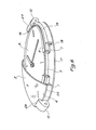
- FIGS. 1, 2 and 3 show a watch case according to a first embodiment of the invention.
- This box has a middle part 1 inside which is housed a movement 2 surmounted by a dial 3. Above the dial appear the hands 4.
- the box also has a crystal 5 whose peripheral zone 6 completely covers the middle 1
- An enlargement circle 7 is arranged between the movement 2 and the middle part 1.
- the circle 7 carries on its upper part a seal 8.
- the circle is arranged to further understand a second lining 9.
- the box also has two supports 10 and 11 which face each other and which are integral with the middle part.
- the supports 10 and 11 each have a portion 12 which projects beyond the side walls of the middle part.
- a hole 13 in which a bar 14 is threaded to hold in place a bracelet 15.
- the supports 10 and 11 form with the middle part 1 grooves 16 in which the crystal 5 can be engaged by its peripheral zone 6
- the crystal 5 also carries on its lower face a metallization 29 intended to hide from the gaze the upper edge 19 of the middle part, the lining 8 and the flange 30.
- Figure 2 shows a support 10 made in one piece with the middle part 1 and a portion 12 used to attach a bracelet. Note, however, that the support 10 could be integral with the middle without forming a single piece with it. It could for example be fixed there by means of screws. Similarly, the support 10 could not include the portion 12 and the hole 13 but a simple connecting piece to join the support to the middle part.
- the box also includes means for moving the enlargement circle 7 which can be actuated from outside the box to compress the lining 8 against the internal face of the crystal 5. It can be seen in FIG. 2 that the box has a bottom 17 screwed to the middle 1 by screws 18.
- the circle 7 is independent of the background. It is then necessary, to make the box waterproof from below, to provide the second lining 9. On the other hand, if the circle 7 were made in one piece with the bottom 17, the lining 9 would be superfluous.
- the glass 5 has at least in its peripheral zone 6 a spherical shape of substantially constant thickness. In the figures, this sphericity is continuous over the entire ice. There could however be other embodiments where, beyond the peripheral zone 6, towards the center of the watch, the crystal would have another radius of curvature.
- the upper face of the middle part referenced 19 has the shape of a portion of a sphere whose radius is substantially equal to the radius of the internal face 25 of the crystal belonging to the peripheral zone 6.
- the glass once in place but not yet fixed, rests its inner spherical face on the top of the middle also having a spherical curvature of the same radius as that of the inner face of the glass.
- FIG. 4 we will now refer to FIG. 4 to understand how the watch case according to the invention is assembled.
- the middle part 1 is shown with its supports 10 and 11 which are integral with it.
- the upper face 19 of the middle part has the shape of a portion of a sphere and forms with the supports 10 and 11 the grooves 16.
- the crystal 5 is shown separated from the middle. Firstly, the internal face 25 of the crystal 5 is slid onto the upper face 19 of the middle in the direction of the arrow 20.
- the glass is then animated by a rotating movement which naturally results from the sliding of the spherical surface. presented by the underside of the crystal on the portion of a sphere presented by the top of the middle 19.
- the peripheral zones 6 of the crystal 5 are made to penetrate into the grooves 16 and this until the the periphery of the crystal coincides with the edge of the middle.
- the seal is compressed (not shown in this figure) corere the inner face of the glass by actuating the means movement of the enlargement circle (not shown) to finally block the glass 5 against the supports 10 and 11.
- the supports 10 and 11 extend on the upper face of the glass at least up to the right of the seal 8. This way of doing makes it possible to use very thin glass, of the order of 0.5 to 0.8 mm thick, because it avoids deformations which could arise at the location of the contact surfaces, which would result in poor sealing at the location of the edges of the glass not covered by the supports.
- the watch case illustrated in FIGS. 1 to 4 also shows that we are dealing with a shape box where the crystal is a spherical cap cut in a rectangular configuration cut to match the shape of the box.
- the supports 10 and 11 are located at the place of rectilinear portions presented by the periphery of the glass.
- Other shapes could be envisaged for the periphery of the box.
- supports 10 and 11 are used which extend over a large part of the rectilinear portions presented by the periphery of the box.
- the internal face 21 of the supports 10 and 11 also to have the shape of a portion of a sphere whose radius is substantially equal to the radius of the external peripheral zone of the ice-cap. This way of doing indeed allows a good distribution of the blocking forces acting on the ice. It also gives the object a pleasant aesthetic form.
- FIG. 5 is an alternative embodiment of the construction shown in FIG. 2. It is distinguished only by the shape of the groove 22 formed on the one hand by the support 23, the internal face of which is cut in a bevel and on the other hand by the portion of sphere presented by the top of the middle 19 as was already the case of the construction proposed in FIG. 2. In the construction of FIG. 5, the edge of the glass 5 is inclined to form the bevel 24.
- the circle 7 is moved upwards and the lining 8 is compressed against the internal face of the glass to then block the beveled glass against the bevel of the support 23
- the mounting of the case is the same as that which has been explained in connection with the preceding figures where, firstly, the internal face of the crystal is slid onto the upper face of the middle in a movement turning until the circumference of the glass coincides with the edge of the middle part and where, in a second step, the glass is blocked against the supports of the middle part.
- FIG. 6 is a perspective view of a watch case according to the invention and according to a second embodiment.
- This is a round box on which is fitted a crystal having the shape of a spherical cap with a circular periphery 26.
- the middle part 1 the enlargement circle 7 in which is housed a housing the lining 8, the base 17 fixed to the middle of the screw means 18, the crystal 5, the movement 2 and the two supports facing each other which are in the form of claws 27 and 28.
- the peripheral zone 6 completely covers the middle 1.
- the supports 26 and 27 must be of small width and that the bottom of the grooves 16 must be straight to allow the overall diameter of the ice to pass during the introduction of it.
- FIG. 6 clearly shows the very thin appearance of the watch case produced according to the means proposed by the present invention. This impression of thinness is given on the one hand by the fact that the crystal covers the middle part and on the other hand because the crystal is curved, which makes it possible to locate the peripheral zone of the crystal below the level of the dial 3.
- Figure 7 is a top view of a watch case, partially mounted, according to a third embodiment of the invention.
- the construction shown in Figure 7 shows two supports 37 and 38 extending over an important arc which makes mounting ia la impossible. are as explained in connection with figure 6.
- a middle made made in two parts 30 and 31. For the assembly of the box, we begin by sliding the internal face of the crystal 5 onto the upper face of the middle part 30 according to the rotating movement already mentioned, until the glass comes to lodge at the bottom of the groove 16 formed by the support 37 and the middle 30.
- the upper face of the middle 31 is slid under the glass in the direction of the arrow 39 until said glass fully penetrates into the groove formed in the middle part 31 and the support 38.
- the two parts 30 and 31 are juxtaposed and touch each other by their edges 40 and 41.
- the assembly is continued by introducing from below the circle sealing and movement and the whole is fixed securely together by screwing the base on the middle as has already been explained with reference to the previous figures.
- this way of doing also allows the mounting of a middle part which carries more than two supports.
- a middle part which carries more than two supports.
- This way of doing things can also be implemented for boxes of rectangular shape where each of the four edges of the glass is retained by a support, two serving to hang a bracelet and the other two serving as decoration.
- the positioning of the glass by sliding in an arc of a circle is the most suitable means for said positioning.
- the supports are secured to the middle by screws for example, we could first apply ice to the middle from the top and then fix the supports afterwards. This way of doing, however, requires two simultaneous actions which complicate the reassembly and which can lead to breakage or deformation of the crystal because it will be necessary to press it while the supports are fixed to the middle. According to the present invention, we will first fix the supports and eisuite only we will proceed to the establishment of the ice puls its fixation by the displacement means described.
Landscapes
- Chemical & Material Sciences (AREA)
- Crystallography & Structural Chemistry (AREA)
- Physics & Mathematics (AREA)
- General Physics & Mathematics (AREA)
- Electric Clocks (AREA)
- Telephone Function (AREA)
- Making Paper Articles (AREA)
Applications Claiming Priority (2)
| Application Number | Priority Date | Filing Date | Title |
|---|---|---|---|
| CH150785A CH660277GA3 (de) | 1985-04-09 | 1985-04-09 | |
| CH1507/85 | 1985-04-09 |
Publications (2)
| Publication Number | Publication Date |
|---|---|
| EP0197518A1 true EP0197518A1 (de) | 1986-10-15 |
| EP0197518B1 EP0197518B1 (de) | 1989-11-29 |
Family
ID=4212056
Family Applications (1)
| Application Number | Title | Priority Date | Filing Date |
|---|---|---|---|
| EP86104591A Expired EP0197518B1 (de) | 1985-04-09 | 1986-04-04 | Uhrengehäuse |
Country Status (7)
| Country | Link |
|---|---|
| US (1) | US4727525A (de) |
| EP (1) | EP0197518B1 (de) |
| JP (1) | JPH0636040B2 (de) |
| CH (1) | CH660277GA3 (de) |
| DE (1) | DE3667212D1 (de) |
| HK (1) | HK55990A (de) |
| SG (1) | SG38990G (de) |
Cited By (1)
| Publication number | Priority date | Publication date | Assignee | Title |
|---|---|---|---|---|
| US8672011B2 (en) | 2006-07-11 | 2014-03-18 | Sumitomo Rubber Industries, Ltd. | Rubber composition for bead apex and tire having bead apex prepared using same |
Families Citing this family (7)
| Publication number | Priority date | Publication date | Assignee | Title |
|---|---|---|---|---|
| CH671494B5 (de) * | 1988-02-09 | 1990-03-15 | Phare Jean D Eve Sa Le | |
| CH678254B5 (de) * | 1990-02-16 | 1992-02-28 | Rado Montres Sa | |
| DE19857860A1 (de) * | 1998-12-15 | 2000-06-21 | Mannesmann Vdo Ag | Zeigerinstrument |
| USD469364S1 (en) | 2001-12-20 | 2003-01-28 | A.T.X. International, Inc. | Watch with rectangular face and beveled glass |
| EP1716460A2 (de) * | 2004-02-20 | 2006-11-02 | Daniel Lazaretnik | Oval geformte uhren und stammanordnung für uhren |
| CN101488006B (zh) * | 2008-05-13 | 2012-07-11 | 张和国 | 一种呈四面拱状玻璃的制备方法和应用 |
| DE102015204619A1 (de) * | 2015-03-13 | 2016-09-15 | Levitation AG | Verfahren zum Herstellen eines Uhrglases mit mindestens einem Schmuckstein |
Citations (4)
| Publication number | Priority date | Publication date | Assignee | Title |
|---|---|---|---|---|
| CH283122A (fr) * | 1944-09-16 | 1952-05-31 | Schmitz Werner | Boîte de montre quadrilatérale. |
| GB814187A (en) * | 1956-06-18 | 1959-06-03 | Smith & Sons Ltd S | Improvements in indicating instruments |
| DE1837081U (de) * | 1961-07-06 | 1961-08-31 | Johann Jaeckle Metallwarenfabr | Glasdeckel fuer uhren mit reif aus kunststoff. |
| EP0168010A1 (de) * | 1984-07-12 | 1986-01-15 | Montres Rado S.A. | Uhrengehäuse |
Family Cites Families (7)
| Publication number | Priority date | Publication date | Assignee | Title |
|---|---|---|---|---|
| US1333194A (en) * | 1918-12-12 | 1920-03-09 | Louis E F Wachter | Watch |
| US1536607A (en) * | 1924-10-09 | 1925-05-05 | Buhlman Herman | Watchcase bezel |
| US2792684A (en) * | 1956-04-13 | 1957-05-21 | Dinstman Hyman | Crystal and bezel assembly |
| CH643424B (fr) * | 1981-03-30 | Arnoux Cesar Sa | Boite de montre. | |
| CH643425B (fr) * | 1981-06-01 | Rado Montres Sa | Boite de montre. | |
| CH642810B (fr) * | 1981-12-02 | Rado Montres Sa | Boite de montre. | |
| US4558956A (en) * | 1983-12-20 | 1985-12-17 | Mondaine Watch Ltd. | Water-tight watch |
-
1985
- 1985-04-09 CH CH150785A patent/CH660277GA3/fr not_active IP Right Cessation
-
1986
- 1986-03-19 US US06/841,412 patent/US4727525A/en not_active Expired - Lifetime
- 1986-04-04 EP EP86104591A patent/EP0197518B1/de not_active Expired
- 1986-04-04 DE DE8686104591T patent/DE3667212D1/de not_active Expired - Lifetime
- 1986-04-07 JP JP61078424A patent/JPH0636040B2/ja not_active Expired - Lifetime
-
1990
- 1990-06-02 SG SG389/90A patent/SG38990G/en unknown
- 1990-07-26 HK HK559/90A patent/HK55990A/xx not_active IP Right Cessation
Patent Citations (4)
| Publication number | Priority date | Publication date | Assignee | Title |
|---|---|---|---|---|
| CH283122A (fr) * | 1944-09-16 | 1952-05-31 | Schmitz Werner | Boîte de montre quadrilatérale. |
| GB814187A (en) * | 1956-06-18 | 1959-06-03 | Smith & Sons Ltd S | Improvements in indicating instruments |
| DE1837081U (de) * | 1961-07-06 | 1961-08-31 | Johann Jaeckle Metallwarenfabr | Glasdeckel fuer uhren mit reif aus kunststoff. |
| EP0168010A1 (de) * | 1984-07-12 | 1986-01-15 | Montres Rado S.A. | Uhrengehäuse |
Cited By (1)
| Publication number | Priority date | Publication date | Assignee | Title |
|---|---|---|---|---|
| US8672011B2 (en) | 2006-07-11 | 2014-03-18 | Sumitomo Rubber Industries, Ltd. | Rubber composition for bead apex and tire having bead apex prepared using same |
Also Published As
| Publication number | Publication date |
|---|---|
| SG38990G (en) | 1990-09-07 |
| JPS61235788A (ja) | 1986-10-21 |
| CH660277GA3 (de) | 1987-04-15 |
| US4727525A (en) | 1988-02-23 |
| DE3667212D1 (de) | 1990-01-04 |
| EP0197518B1 (de) | 1989-11-29 |
| HK55990A (en) | 1990-08-03 |
| JPH0636040B2 (ja) | 1994-05-11 |
Similar Documents
| Publication | Publication Date | Title |
|---|---|---|
| EP0873543B1 (de) | Uhrengehäuse mit einer schale und einer haltevorrichtung | |
| EP0541001B1 (de) | Uhrengehäuse mit einem abnehmbaren Boden | |
| WO1998028156A1 (fr) | Instrument d'ecriture, notamment un stylo | |
| EP0197518B1 (de) | Uhrengehäuse | |
| EP3680729B1 (de) | Ausrichtbarer boden für eine uhr | |
| EP0770939A1 (de) | Uhr mit einem ein Uhrwerk umfassenden Gehäuse | |
| EP0327829A1 (de) | Wasserdichtes Uhrengehäuse | |
| EP0168010B1 (de) | Uhrengehäuse | |
| EP0072345A1 (de) | Uhrgehäuse | |
| EP1388028B1 (de) | Uhr mit einem auswechselbaren zifferblatt | |
| EP0600389B1 (de) | Uhrengehäuse mit einem ausgehöhlten Mittelteil | |
| EP0269872B1 (de) | Uhrengehäuse | |
| CH696090A5 (fr) | Montre-bracelet à boîtier réversible. | |
| EP1102136B1 (de) | Vorrichtung zum Aufsetzen einer Schutzkappe aus hartem Material auf den Mittelteil einer Uhr | |
| EP1189117B1 (de) | Armbanduhr mit umkehrbarem Gehäuse | |
| EP0383179B1 (de) | Uhrengehäuse mit einer Schutzkappe aus hartem Material | |
| EP3779606A1 (de) | Armbanduhr mit automatischem aufzug | |
| FR2476340A1 (fr) | Boitier de montre compose de deux parties emboitables a la maniere d'un tiroir | |
| CH646570A5 (en) | Watch case | |
| FR2507348A1 (fr) | Ensemble plaque de cadran et boite de dispositif d'horlogerie et leur procede d'assemblage | |
| EP4332690A1 (de) | Armbanduhrgehäuse für armbanduhr mit musik- oder schlagwerk, die einen boden mit deckel umfasst | |
| CH541829A (fr) | Boîte de montre comprenant un verre en matière dure | |
| EP1701228A2 (de) | Uhr | |
| CH664251GA3 (en) | Attachment gold watch case with axially immobilised caging ring - ensures perpendicular to axis by projection engaging with corresp. part of centre | |
| WO2001061243A1 (fr) | Luminaire comportant deux parties assemblees de facon etanche |
Legal Events
| Date | Code | Title | Description |
|---|---|---|---|
| PUAI | Public reference made under article 153(3) epc to a published international application that has entered the european phase |
Free format text: ORIGINAL CODE: 0009012 |
|
| AK | Designated contracting states |
Kind code of ref document: A1 Designated state(s): DE FR GB |
|
| 17P | Request for examination filed |
Effective date: 19861025 |
|
| 17Q | First examination report despatched |
Effective date: 19880218 |
|
| GRAA | (expected) grant |
Free format text: ORIGINAL CODE: 0009210 |
|
| AK | Designated contracting states |
Kind code of ref document: B1 Designated state(s): DE FR GB |
|
| REF | Corresponds to: |
Ref document number: 3667212 Country of ref document: DE Date of ref document: 19900104 |
|
| GBT | Gb: translation of ep patent filed (gb section 77(6)(a)/1977) | ||
| PLBE | No opposition filed within time limit |
Free format text: ORIGINAL CODE: 0009261 |
|
| PLBE | No opposition filed within time limit |
Free format text: ORIGINAL CODE: 0009261 |
|
| STAA | Information on the status of an ep patent application or granted ep patent |
Free format text: STATUS: NO OPPOSITION FILED WITHIN TIME LIMIT |
|
| 26N | No opposition filed | ||
| 26N | No opposition filed | ||
| REG | Reference to a national code |
Ref country code: GB Ref legal event code: IF02 |
|
| PGFP | Annual fee paid to national office [announced via postgrant information from national office to epo] |
Ref country code: GB Payment date: 20050325 Year of fee payment: 20 |
|
| PGFP | Annual fee paid to national office [announced via postgrant information from national office to epo] |
Ref country code: DE Payment date: 20050401 Year of fee payment: 20 |
|
| PGFP | Annual fee paid to national office [announced via postgrant information from national office to epo] |
Ref country code: FR Payment date: 20050427 Year of fee payment: 20 |
|
| PG25 | Lapsed in a contracting state [announced via postgrant information from national office to epo] |
Ref country code: GB Free format text: LAPSE BECAUSE OF EXPIRATION OF PROTECTION Effective date: 20060403 |
|
| REG | Reference to a national code |
Ref country code: GB Ref legal event code: PE20 |