EP0197557A2 - Dispositif de commutation - Google Patents
Dispositif de commutation Download PDFInfo
- Publication number
- EP0197557A2 EP0197557A2 EP86104871A EP86104871A EP0197557A2 EP 0197557 A2 EP0197557 A2 EP 0197557A2 EP 86104871 A EP86104871 A EP 86104871A EP 86104871 A EP86104871 A EP 86104871A EP 0197557 A2 EP0197557 A2 EP 0197557A2
- Authority
- EP
- European Patent Office
- Prior art keywords
- contact
- actuator
- switch
- latch lever
- switch assembly
- Prior art date
- Legal status (The legal status is an assumption and is not a legal conclusion. Google has not performed a legal analysis and makes no representation as to the accuracy of the status listed.)
- Withdrawn
Links
Images

Classifications
-
- H—ELECTRICITY
- H01—ELECTRIC ELEMENTS
- H01H—ELECTRIC SWITCHES; RELAYS; SELECTORS; EMERGENCY PROTECTIVE DEVICES
- H01H3/00—Mechanisms for operating contacts
- H01H3/02—Operating parts, i.e. for operating driving mechanism by a mechanical force external to the switch
- H01H3/16—Operating parts, i.e. for operating driving mechanism by a mechanical force external to the switch adapted for actuation at a limit or other predetermined position in the path of a body, the relative movement of switch and body being primarily for a purpose other than the actuation of the switch, e.g. for a door switch, a limit switch, a floor-levelling switch of a lift
- H01H3/161—Operating parts, i.e. for operating driving mechanism by a mechanical force external to the switch adapted for actuation at a limit or other predetermined position in the path of a body, the relative movement of switch and body being primarily for a purpose other than the actuation of the switch, e.g. for a door switch, a limit switch, a floor-levelling switch of a lift for actuation by moving a closing member, e.g. door, cover or lid
- H01H3/163—Operating parts, i.e. for operating driving mechanism by a mechanical force external to the switch adapted for actuation at a limit or other predetermined position in the path of a body, the relative movement of switch and body being primarily for a purpose other than the actuation of the switch, e.g. for a door switch, a limit switch, a floor-levelling switch of a lift for actuation by moving a closing member, e.g. door, cover or lid associated with locking or manipulating means of the closing member
Definitions
- the present invention relates to a swith assembly which can be used, for example, as a door-sctuated switch for an electronic cocking range.
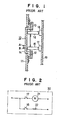
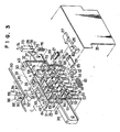
- Figs. 1 and 2 of the accompanying drawings show a hitherto known swith assembly of the type mentioned above and application thereof to an electronic cocking range or the like.
- a switch assembly denoted by a reference numeral 10 is constituted by slider guides 12 and 13 mounted on a base panel 11, a slider member 14 inserted in the guides 12 and 13 slidably selectively in the directions indicated by arrows A and B, switch elements 17 and 18 having respective levers 15 and 16 of which inclinations are changed by the movement of the slider member, and a printed circuit board 19 on which the switch elements 17 and 18 are mounted.
- the switch elements 17 and 18 respond therto to be thereby turned on (i.e. closed), resulting in that an electric motor 21 and a coil 22 incorporated in the electronic range 20, as shown in Fig. 2 ,,are electrically energized.
- both the switch elements 17 and 18 are simultaneously turned on or off.
- the motor 21 and the coil 22 are electrically energized simultaneously, giving rise to a large amount of starting current flow as a whole.
- the hitherto known electronic range 20 the above problem is dealt with by using a fuse having a large current capacity.
- such measures are ineffective to reduce the maximum starting current.
- an attempt to reduce the maximum starting current by actuating the switch elements 17 and 18 at different time points deviated slitely from each other to thereby make the supply of the starting current to the motor 21 be deviated correspondingly from that of the coil 22 has been proposed and actually adopted in some of the electronic cocking ranges.
- Another object of the present invention is to provide a switch assembly which is capable of suppressing the maximum current supplied to an electric circuit upon switch operation to a possible minimum value.
- a further object of the present invention is to provide a switch assembly which can be mounted on an electronic device as an electronic cocking range in a much facilitated and simplified manner.
- a switch assembly which includes a latch mechanism mounted detacheably relative to a main body of the switch assembly, a first contact adapted to'be operated when a latch lever of the latch mechanism is inserted in the switch main.body with the lever being in the latched state, and a second contact operated when the aforementioned latch lever inserted in the switch main body is released from the latched state.
- the switch assembly With the arrangement of the switch assembly according to the present invention, it is possible to actuate a plurality of contacts at different time points deviated one another through a single operation such as door latch operation in an electronic cocking range. Consequently, the simultaneous supply of starting currents to associated circuits can be prevented, while the overall starting current can be supplessed to a minimum value.
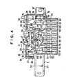
- Fig. 3 shows in an exploded perspective view a switch assembly according to an exemplary embodiment of the invention.
- the switch assembly generally denoted by a reference numeral 25 is intended to be employed as an interlock switch for an electronic cocking range or the like.
- the switch assembly 25 is so arranged that contact operation timings thereof are deviated one another upon latching of the door of the electronic range.
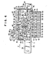
- the switch assembly 25 i s basically composed of a switch main body 1, first to fourth actuators 26 to 29, and a latch mechanism 2, as will be described below in detail.
- the switch main body 1 is composed of an top plate 30, aide plates 31 and 32 and a rear plate 33 which cooperate to constitute a housing 34 of an integral structure, and a cover 35 adapted to close the front of the housing 34.
- the side plates 31 and 33 have respective blackets 36 and 37 for mounting the switch main body on an electronic range, by way of example.
- the top plate 30 has vertical apertures 38, 39 and 40 formed therethrough.
- guide means 8 and 9 Disposed fixedly within an upper cavity portion of the housing 34 are guide means 8 and 9 serving as guides for allowing the first actuator 26 and the fourth actuator 29 to be slidably displaced in the horizontal transverse direction, a shaft 7 for supporting rotatably the second actuator 27, and a guide piece 41 for guiding the sliding movement of the third actuator 28 in the vertical direction, while a contact support 42 holding a plurality of contacts is disposed within a lower cavity portion of the housing 34.
- the aforementioned guide means 8 includes a guide piece 43 of a generally crank-like configuration, a pair of guide pieces 44 and 45 disposed at one side of the guide piece 43, and lower frames or collars 46 and 47 defining the aforementioned apertures 38 and 39 respectively.
- the guide means 9 is constituted by a part of the aforementioned guide piece 43, a pair of guide pieces 48 and 49 disposed at the other side of the guide piece 43, and a recess 50 formed at an upper corner of the housing 34.
- the contact support 42 includes a pair of horizontal plates 51 and 52 for supporting terminals 53 to 60 and a plurality of vertical plates 61 for separating the terminals 53 to 60 from one another.
- Common contacts 65 and 62 are connected to the terminals 56 and 59 respectively, while contacts 63, 64, 5, 66, 4 and 68 are connected to the terminals 53, 54, 55, 57, 58 and 60 respectively. Movement or stroke of the contact 63 is restricted by a strobe limiting bar 69.
- the contact 63 is detached from the contact 64.
- the common contact 65 in the free state is brought into contact with the contact 66 whose movement is restricted by stroke limit bars 70 and 71, while the contact 65 is detached from the contact 5 whose movement is restricted by a stroke limit bar 72.
- a coil of an electronic cocking range (not shown ) is electrically energized.
- the common contact 62 in the free state is in contact with the contact 68 and detached from the contact 4, an electric motor (not shown ) of the electronic range is electrically energized.
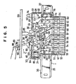
- the first actuator 26 has one end ( pushing end ) 67 sandwiched slidably between the guide pieces 44 and 45 and the other end portion also sandwiched between the lower frame 46 and the guide piece 43.
- the common contact 62 is bent in this direction by means of the pushing end 67.
- the stroke of the first actuator is restricted by the lower frame 47.
- the second actuator 27 includes a cylindrical member 24 mounted rotatably on the shaft 7 and an actuator arm 99 mounted on the cylindrical member 24 in a tangential relation thereto. In the free state of the second actuator 27, one end of the actuator arm 99 is in contact with the contact 4, whereby the other end of the actuator arm 99 is urged to lie within the aperture 39 under a resilient force of the contact 4.
- the third actuator 28 includes a slider body 73 of a substantially rectangular configuration, a rod-like pushing portion 74 disposed on the top of the slider body 73, an actuating piece 75 of L-like cross-section disposed at one side of the slider body 73, and a compression spring 76 urging upwardly the slider body 73.
- the fourth actuator 29 includes a plate-like member 81 having a notch 80 formed at one end, an actuator block 82 of a substantially inverted C-like configuration disposed at the other end of the plate-like member 81, and a compression spring 83 for biasing the fourth actuator 29 in the direction indicated by the arrow C.
- the fourth actuator 29 is slidably mounted within the recess 50 so as to be positioned by the guide pieces 43, 48 and 49. Subsequently, the compression spring 83 is placed between the actuator block 82 and a spring accommodating portion 84 formed in the housing 34.
- the fourth actuator 29 is resiliently biased or urged in the direction indicated by the arrow C under the influence of the compression spring 83 with the actuator block 82 bearing against the guide piece 49.
- the top end of the °common contact 65 is brought into contact with the periphery of the notch 80, while the upper end of the contact 64 is placed in contact with a pushing edge 85 of the plate-like member 81.
- the latch mechanism 2 includes a stud 86 mounted on a door 110 of an electronic range or the like, a latch lever 3 adapted to be inserted in an through-hole 87 formed in the door 11 0 , a shaft or pin 89 for suppoting rotatably a pushing or pressing portion 88 of the latch lever 3 on the stud 86, and a compression spring 80 interposed between the lower face of the pushing portion 88 and the upper surface of the door 110.
- the latch lever 3 In the free state, the latch lever 3 is held at a position at which the latch lever 3 is in contact with an edge 91 of the throughhole 87 under the urging force of the compression spring 90.
- a projection 95 is formed on the lower surface of the door 110 at a position located immediately above the aperture 39 so as to'be inserted therein upon closing of the door 110.
- the lower end of the latch lever 3 bears against the first actuator 26 to cause the latter to slide in the direction C.
- the pushing end 67 of the first actuator 26 bears against the upper end of the common contact 62 which is thus flexed in the direction C.
- the finger is removed from the latch lever 3.
- the latch lever 3 is rotated in the direction indicated by an arrow D under the spring force of the compression spring 90, as shown in fig. 7, whereby the actuator block 82 is slidingly displaced in the direction opposite to that indicated by the arrow C by means of the actuator portion 92 of the latch lever 3.
- the common contact 65 inserted in the notch of the plate-like member 81 is flexed in the direction opposite to that indiocated by the arrow C to be ultimately contacted with the contact 5, whereupon the coil of the electronic range is electrically energized.
- the contact 64 is flexed in the direction opposite to the arrow C by means of the pushing edge of the plate-like member 81 to be contacted with the contact 63.
- the first actuator 26 is released from the action exerted by the latch lever 3.
- the pushing portion 88 of the latch lever 3 is depressed by a finger of the user, being followed by disengagement of the door 110 from the switch assembly 1.
- the coil of the electronic range is first turned off and thereafter the electric motor is turned off through the process excuted in the sequence reverse to the operation.
- the switch assembly embodying the invention is so arranged that only after the contact has been made between the common contact 62 and the contact 4 under the action of the latch lever 3 upon closing'of the door 110, the common contact 65 is brought into contact 5. Accordingly, the starting time point of the electric motor is deviated from that of the coil, whereby the simultaneous supply of the starting currents to the motor and the coil is positively inhibited.
- the fourth actuator 26 is not used for the contact changeover operation.
- the fourth actuator 26 is adapted to be moved in the direction C by means of the latch lever 3, whereby a common contact disposed adjacent to the common contact 62 is flexed in the direction C to be contacted with a contact disposed in the vicinity of the contact 68, as the result of which the fourth actuator 29 is restored to the original position under the action of the common contact upon releasing of the latch lever 3 from the latched state.
Landscapes
- Engineering & Computer Science (AREA)
- Computer Security & Cryptography (AREA)
- Mechanisms For Operating Contacts (AREA)
- Switch Cases, Indication, And Locking (AREA)
- Switches With Compound Operations (AREA)
Applications Claiming Priority (2)
| Application Number | Priority Date | Filing Date | Title |
|---|---|---|---|
| JP5168085U JPH0411315Y2 (fr) | 1985-04-09 | 1985-04-09 | |
| JP51680/85U | 1985-04-09 |
Publications (2)
| Publication Number | Publication Date |
|---|---|
| EP0197557A2 true EP0197557A2 (fr) | 1986-10-15 |
| EP0197557A3 EP0197557A3 (fr) | 1989-03-15 |
Family
ID=12893596
Family Applications (1)
| Application Number | Title | Priority Date | Filing Date |
|---|---|---|---|
| EP86104871A Withdrawn EP0197557A3 (fr) | 1985-04-09 | 1986-04-09 | Dispositif de commutation |
Country Status (2)
| Country | Link |
|---|---|
| EP (1) | EP0197557A3 (fr) |
| JP (1) | JPH0411315Y2 (fr) |
Cited By (1)
| Publication number | Priority date | Publication date | Assignee | Title |
|---|---|---|---|---|
| EP0392200A1 (fr) * | 1989-04-13 | 1990-10-17 | Ellenberger & Poensgen GmbH | Dispositif de verrouillage à sécurité pour une porte d'appareil électrique |
Family Cites Families (3)
| Publication number | Priority date | Publication date | Assignee | Title |
|---|---|---|---|---|
| US3691329A (en) * | 1971-10-04 | 1972-09-12 | Appliance Mfg Co Inc | Control switch for microwave oven |
| US4516007A (en) * | 1982-08-19 | 1985-05-07 | Litton Systems, Inc. | Interlock switch module for a microwave oven |
| US4528430A (en) * | 1983-07-12 | 1985-07-09 | Cherry Electrical Products Corporation | Electrical appliance interlock switch with force efficient actuator |
-
1985
- 1985-04-09 JP JP5168085U patent/JPH0411315Y2/ja not_active Expired
-
1986
- 1986-04-09 EP EP86104871A patent/EP0197557A3/fr not_active Withdrawn
Cited By (1)
| Publication number | Priority date | Publication date | Assignee | Title |
|---|---|---|---|---|
| EP0392200A1 (fr) * | 1989-04-13 | 1990-10-17 | Ellenberger & Poensgen GmbH | Dispositif de verrouillage à sécurité pour une porte d'appareil électrique |
Also Published As
| Publication number | Publication date |
|---|---|
| JPH0411315Y2 (fr) | 1992-03-19 |
| JPS61168526U (fr) | 1986-10-18 |
| EP0197557A3 (fr) | 1989-03-15 |
Similar Documents
| Publication | Publication Date | Title |
|---|---|---|
| US4002874A (en) | Double-throw rocker switch with selective lockout means | |
| JP3749371B2 (ja) | 押ボタンスイッチ | |
| US3927284A (en) | Keyboard switch assembly having coil spring contacts providing point contacts engagement | |
| US3519775A (en) | Rocker switch centered by circular loop spring members coiled in compression | |
| JPH05217464A (ja) | プッシュ機構付きスライドスイッチ | |
| GB1558752A (en) | Lockale leveroperated device | |
| US4035596A (en) | Electrical switch construction | |
| US3731030A (en) | Pushbutton switch assembly with pivotable conductive bridging member and multiple conductive path printed circuit board | |
| JP2005032556A (ja) | スイッチ装置 | |
| US4307361A (en) | Electric control apparatus with an electromechanical latch device | |
| JPH04108844U (ja) | 接続器 | |
| JPS5819825A (ja) | スイツチ作動機構 | |
| US3821534A (en) | Hinged keyboard switch | |
| US3922513A (en) | Key switch apparatus | |
| US3842229A (en) | Keyboard pushbutton switch | |
| JPS5924522B2 (ja) | スイツチ付きスライド形可変抵抗器 | |
| US4795860A (en) | Push switch | |
| US3448417A (en) | Key switch assembly | |
| US2905773A (en) | Electric switches | |
| JPH113630A (ja) | プッシュスイッチ及びその組立て方法 | |
| US3903384A (en) | Multipole slide-type disconnect switch having multi-linkage operating means and shutter member | |
| US5376764A (en) | Three-way switch | |
| US3204070A (en) | Momentary switch using resilient leaf spring actuator | |
| JPH0631620Y2 (ja) | キーボードスイッチ | |
| US7330091B2 (en) | Electronic type protective relay |
Legal Events
| Date | Code | Title | Description |
|---|---|---|---|
| PUAI | Public reference made under article 153(3) epc to a published international application that has entered the european phase |
Free format text: ORIGINAL CODE: 0009012 |
|
| AK | Designated contracting states |
Kind code of ref document: A2 Designated state(s): AT BE CH DE FR GB IT LI LU NL SE |
|
| PUAL | Search report despatched |
Free format text: ORIGINAL CODE: 0009013 |
|
| AK | Designated contracting states |
Kind code of ref document: A3 Designated state(s): AT BE CH DE FR GB IT LI LU NL SE |
|
| 17P | Request for examination filed |
Effective date: 19890307 |
|
| 17Q | First examination report despatched |
Effective date: 19900727 |
|
| STAA | Information on the status of an ep patent application or granted ep patent |
Free format text: STATUS: THE APPLICATION IS DEEMED TO BE WITHDRAWN |
|
| 18D | Application deemed to be withdrawn |
Effective date: 19911104 |
|
| RIN1 | Information on inventor provided before grant (corrected) |
Inventor name: KITAMURA, TAKAOPATENT CENTER Inventor name: NISHIMURA, YASUHIDEPATENT CENTER Inventor name: NOGUCHI, MASAYOSHIPATENT CENTER Inventor name: YAMANE, NORIHITOPATENT CENTER |