EP0197575B1 - Procédé et appareil pour délivrer un liquide visqueux, utilisant un clapet - Google Patents
Procédé et appareil pour délivrer un liquide visqueux, utilisant un clapet Download PDFInfo
- Publication number
- EP0197575B1 EP0197575B1 EP19860200381 EP86200381A EP0197575B1 EP 0197575 B1 EP0197575 B1 EP 0197575B1 EP 19860200381 EP19860200381 EP 19860200381 EP 86200381 A EP86200381 A EP 86200381A EP 0197575 B1 EP0197575 B1 EP 0197575B1
- Authority
- EP
- European Patent Office
- Prior art keywords
- outlet
- valve
- valve member
- liquid
- shoulder
- Prior art date
- Legal status (The legal status is an assumption and is not a legal conclusion. Google has not performed a legal analysis and makes no representation as to the accuracy of the status listed.)
- Expired
Links
- 239000007788 liquid Substances 0.000 title claims description 30
- 238000000034 method Methods 0.000 title claims description 9
- 230000007704 transition Effects 0.000 claims description 2
- 238000010276 construction Methods 0.000 description 2
- -1 polytetrafluoroethylene Polymers 0.000 description 2
- 229920001343 polytetrafluoroethylene Polymers 0.000 description 2
- 239000004810 polytetrafluoroethylene Substances 0.000 description 2
- 229910001220 stainless steel Inorganic materials 0.000 description 2
- 239000010935 stainless steel Substances 0.000 description 2
- 238000004140 cleaning Methods 0.000 description 1
- 230000003749 cleanliness Effects 0.000 description 1
- 239000013013 elastic material Substances 0.000 description 1
- 230000005484 gravity Effects 0.000 description 1
- 230000012447 hatching Effects 0.000 description 1
- 239000000463 material Substances 0.000 description 1
- 238000007789 sealing Methods 0.000 description 1
- 230000035939 shock Effects 0.000 description 1
Images
Classifications
-
- B—PERFORMING OPERATIONS; TRANSPORTING
- B65—CONVEYING; PACKING; STORING; HANDLING THIN OR FILAMENTARY MATERIAL
- B65B—MACHINES, APPARATUS OR DEVICES FOR, OR METHODS OF, PACKAGING ARTICLES OR MATERIALS; UNPACKING
- B65B39/00—Nozzles, funnels or guides for introducing articles or materials into containers or wrappers
- B65B39/001—Nozzles, funnels or guides for introducing articles or materials into containers or wrappers with flow cut-off means, e.g. valves
- B65B39/004—Nozzles, funnels or guides for introducing articles or materials into containers or wrappers with flow cut-off means, e.g. valves moving linearly
Definitions
- This invention relates to a method for dispensing a viscous liquid, using a valve comprising a body having an inlet and an outlet and a valve member movable perpendicularly to the plane of said outlet, wherein as soon as the entire desired quantity of liquid has passed the outlet the valve member is moved to the outlet at such a velocity, that by suddenly decelerating upon closing the outlet the last quantity of liquid is pushed through the outlet.
- the bottom surface thereof in the end position of the valve member, is coplanar with the end of the outlet and the outlet is fully filled up and the liquid will be fully released from the valve member.
- valve member can be decelerated with a shock or optionally shockwise in a plurality of steps, whereas the liquid continues to advance under the influence of inertia. As the desired quantity of liquid is forced through the outlet as one whole, no liquid will cling to the wall of the outlet.
- the liquid is pushed outward in the vertical, downward direction.
- the amount of liquid is released from the decelerated valve member not only on the basis of inertia, but in addition by gravity.
- the invention further relates to an apparatus for carrying out the methods according to the invention, comprising a valve including a body having an inlet and an outlet and a valve member adapted to close said outlet and movable perpendicularly to the plane of the outlet, wherein the valve member includes a shoulder which in the closed condition of the valve is in contact with the valve seat of the outlet and which construction is characterized in that the form and dimensions of the valve member correspond to those of the outlet, so that, in the closed end position of the valve, the bottom surface of the valve member is co-planar with the end of the outlet and the outlet is fully filled up. In this way no liquid can remain behind in the outlet.
- the shoulder of the valve member strikes the seat, so that the valve member is abruptly stopped. As a consequence, the contact between the valve member and the liquid is broken, so that the liquid is moved along into the container and does not cling to the valve, thus preventing the latter from starting to drip, as no liquid can be present between the valve member and the valve seat.
- the transition between the shoulder and the valve member is rounded, and the associated part of the valve seat is similarly rounded.
- the result of this rounding is that the valve member is centred as it is pushed into the outlet. As it is further pushed through the outlet, the valve member will then come to lie in proper sealing relationship with the inner wall of the outlet. As the valve member moves into the outlet, liquid present between the valve member or the shoulder and the valve seat is pushed back into the valve along the rounded surfaces, so that, in the closed condition of the valve, no liquid can be present between the valve member and the valve seat.
- the valve member may be made of polytetrafluoroethylene.
- the valve seat may be made of stainless steel, which can easily be cleaned. Such a combination of polytetrafluoroethylene and stainless steel additionally provides for proper guideance of the valve member in the outlet.
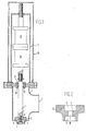
- valve comprising a body 1 with an inlet 2 and an outlet 3.
- the outlet can be closed by a valve member 4 having a shoulder 5.
- Shoulder 5 rests upon a valve seat 6.
- the valve seat has a rounded edge and terminates in a portion defining the outlet 3.
- Valve member 4 is coupled at the top to a driving rod 7.
- the valve member can be fixedly connected to the driving rod, for example, by means of bolt 8 via bores 9, 10 and 11 (see Fig. 2).
- rod 7 is mounted for axial movement by means of a bearing 12 provided with seals 16 and 17.
- the axial movement of the driving rod can be effected with a pneumatic driving system 13 arranged above the valve.
- driving rod 7 is connected to two cylinders 14 and 15, arranged in series, and together providing for a stepped length of stroke of driving rod 7.
- the driving system is shut off from its surroundings by a cover 18.
- valve member 4 When liquid has to be dispensed, for example, a container should be filled, valve member 4 will be raised under the influence of cylinders 14 and 15 and driving rod 7. Liquid can then enter valve 1 through inlet 2 and leave it through outlet 3. When the desired quantity to be withdrawn has almost been reached, valve member 4 is moved downwards at a high velocity by means of cylinders 14 and 15 and driving rod 7. During this movement, the last amount of liquid will be pushed by the valve member through the outlet 3 as a lump. At the moment when all liquid has been pushed through the outlet, and the bottom surface of valve 4 is co-planar with the outlet end, shoulder 5 strikes seat 6 with some force.
- valve member is instantaneously stopped, while-the contact between the liquid and the valve member is broken as a result of the inertia of the liquid.
- valve member 4 As the valve member enters the outlet, it is centered to some extent by the rounded edges of valve seat 6. Subsequently, valve member 4 will come to lie in contact with the valve seat, and any liquid remaining between valve seat 6 and valve member 4 will be forced back into the valve until shoulder 5 is in contact with valve seat 6 and no liquid is left between valve member 4 and valve seat 6.
Landscapes
- Engineering & Computer Science (AREA)
- Mechanical Engineering (AREA)
- Lift Valve (AREA)
- Filling Of Jars Or Cans And Processes For Cleaning And Sealing Jars (AREA)
- Supply Of Fluid Materials To The Packaging Location (AREA)
Claims (5)
Applications Claiming Priority (2)
| Application Number | Priority Date | Filing Date | Title |
|---|---|---|---|
| NL8500680 | 1985-03-11 | ||
| NL8500680A NL8500680A (nl) | 1985-03-11 | 1985-03-11 | Werkwijze en inrichting voor het met behulp van een afsluiter vullen van een verpakking met een viskeuze vloeistof. |
Publications (2)
| Publication Number | Publication Date |
|---|---|
| EP0197575A1 EP0197575A1 (fr) | 1986-10-15 |
| EP0197575B1 true EP0197575B1 (fr) | 1989-01-04 |
Family
ID=19845656
Family Applications (1)
| Application Number | Title | Priority Date | Filing Date |
|---|---|---|---|
| EP19860200381 Expired EP0197575B1 (fr) | 1985-03-11 | 1986-03-10 | Procédé et appareil pour délivrer un liquide visqueux, utilisant un clapet |
Country Status (4)
| Country | Link |
|---|---|
| EP (1) | EP0197575B1 (fr) |
| JP (1) | JPS61274173A (fr) |
| DE (1) | DE3661609D1 (fr) |
| NL (1) | NL8500680A (fr) |
Families Citing this family (4)
| Publication number | Priority date | Publication date | Assignee | Title |
|---|---|---|---|---|
| JP2585247Y2 (ja) * | 1992-03-12 | 1998-11-18 | 四国化工機株式会社 | 液体定量充填ノズル |
| GB2319326B (en) * | 1996-11-11 | 2001-05-09 | Unilever Plc | Dosing apparatus and method |
| IT1289515B1 (it) * | 1996-12-23 | 1998-10-15 | Ronchi Mario Srl Officine Mecc | Valvola con otturatore ad azionamento controllato per l'erogazione dosata di fluidi in macchine automatiche di riempimento di contenitori |
| JP3842870B2 (ja) * | 1997-07-11 | 2006-11-08 | Smc株式会社 | 開閉弁 |
Family Cites Families (2)
| Publication number | Priority date | Publication date | Assignee | Title |
|---|---|---|---|---|
| DE352091C (de) * | 1916-07-20 | 1922-04-24 | Borden Co | Maschine zum Messen und Abfuellen von Fluessigkeiten |
| DE2819245A1 (de) * | 1978-05-02 | 1979-11-15 | Hick & Co Gmbh | Dosiereinrichtung fuer abfuellanlagen |
-
1985
- 1985-03-11 NL NL8500680A patent/NL8500680A/nl not_active Application Discontinuation
-
1986
- 1986-03-10 DE DE8686200381T patent/DE3661609D1/de not_active Expired
- 1986-03-10 EP EP19860200381 patent/EP0197575B1/fr not_active Expired
- 1986-03-11 JP JP5157486A patent/JPS61274173A/ja active Pending
Also Published As
| Publication number | Publication date |
|---|---|
| EP0197575A1 (fr) | 1986-10-15 |
| JPS61274173A (ja) | 1986-12-04 |
| DE3661609D1 (en) | 1989-02-09 |
| NL8500680A (nl) | 1986-10-01 |
Similar Documents
| Publication | Publication Date | Title |
|---|---|---|
| US4410108A (en) | Pressure-actuated valve for use with positive displacement filling machine | |
| US3959061A (en) | Apparatus and method for inserting membrane into container lids | |
| NO952420D0 (no) | Porsjoneringsinnretning | |
| EP1600678A3 (fr) | Dispositif et méthode pour dispenser d'échantillon de peinture et de matière colorante | |
| AU588600B2 (en) | An opening arrangement for packing containers | |
| US4084626A (en) | Automatically operational net weight filling machine | |
| MXPA04010980A (es) | Sistema para el llenado y cerrado de cartuchos que contienen fluido. | |
| AU7666291A (en) | Automatic dispenser for doughy food products | |
| US4254806A (en) | Apparatus for filling caulking tubes in a clean manner | |
| EP0334537B1 (fr) | Dispositif pour remplir à partir du fond | |
| EP0197575A1 (fr) | Procédé et appareil pour délivrer un liquide visqueux, utilisant un clapet | |
| US3336720A (en) | Method of and apparatus for filling aerosol containers | |
| US4000765A (en) | Bottom-up container-filling machine | |
| EP0345602B1 (fr) | Méthode et appareil pour minimiser la mousse lors du remplissage de cartons | |
| US4582103A (en) | Product dispensing apparatus | |
| AU8259187A (en) | A method and an arrangement for a filling valve in a packing machine | |
| US5775387A (en) | Container filling system having fill-pipe with an extended sealing member for reducing mixing of product and air during container filling | |
| JPS5657687A (en) | Method and device for filling highhpurity liquid | |
| US5819823A (en) | Umbrella valve assembly having drip-prevention structure disposed about product fill pipe | |
| GB2069060A (en) | Dispensing viscous substances | |
| US4309860A (en) | Machine for closing a receptacle | |
| EP0101272A3 (fr) | Soupape basculante pour fluides visqueux pour réservoirs sous pression | |
| RU40298U1 (ru) | Клапан дозатора | |
| JPH0639297Y2 (ja) | 充填装置 | |
| JPH0451142Y2 (fr) |
Legal Events
| Date | Code | Title | Description |
|---|---|---|---|
| PUAI | Public reference made under article 153(3) epc to a published international application that has entered the european phase |
Free format text: ORIGINAL CODE: 0009012 |
|
| AK | Designated contracting states |
Kind code of ref document: A1 Designated state(s): BE CH DE FR GB IT LI NL SE |
|
| 17P | Request for examination filed |
Effective date: 19861128 |
|
| 17Q | First examination report despatched |
Effective date: 19870723 |
|
| GRAA | (expected) grant |
Free format text: ORIGINAL CODE: 0009210 |
|
| ITF | It: translation for a ep patent filed | ||
| AK | Designated contracting states |
Kind code of ref document: B1 Designated state(s): BE CH DE FR GB IT LI NL SE |
|
| REF | Corresponds to: |
Ref document number: 3661609 Country of ref document: DE Date of ref document: 19890209 |
|
| ET | Fr: translation filed | ||
| PGFP | Annual fee paid to national office [announced via postgrant information from national office to epo] |
Ref country code: DE Payment date: 19900129 Year of fee payment: 5 |
|
| PGFP | Annual fee paid to national office [announced via postgrant information from national office to epo] |
Ref country code: SE Payment date: 19900206 Year of fee payment: 5 |
|
| PLBE | No opposition filed within time limit |
Free format text: ORIGINAL CODE: 0009261 |
|
| STAA | Information on the status of an ep patent application or granted ep patent |
Free format text: STATUS: NO OPPOSITION FILED WITHIN TIME LIMIT |
|
| 26N | No opposition filed | ||
| PGFP | Annual fee paid to national office [announced via postgrant information from national office to epo] |
Ref country code: BE Payment date: 19900329 Year of fee payment: 5 |
|
| ITTA | It: last paid annual fee | ||
| PGFP | Annual fee paid to national office [announced via postgrant information from national office to epo] |
Ref country code: NL Payment date: 19900331 Year of fee payment: 5 Ref country code: GB Payment date: 19900331 Year of fee payment: 5 |
|
| PGFP | Annual fee paid to national office [announced via postgrant information from national office to epo] |
Ref country code: CH Payment date: 19900615 Year of fee payment: 5 |
|
| PG25 | Lapsed in a contracting state [announced via postgrant information from national office to epo] |
Ref country code: GB Effective date: 19910310 |
|
| PG25 | Lapsed in a contracting state [announced via postgrant information from national office to epo] |
Ref country code: SE Effective date: 19910311 |
|
| PGFP | Annual fee paid to national office [announced via postgrant information from national office to epo] |
Ref country code: FR Payment date: 19910315 Year of fee payment: 6 |
|
| PG25 | Lapsed in a contracting state [announced via postgrant information from national office to epo] |
Ref country code: LI Effective date: 19910331 Ref country code: CH Effective date: 19910331 Ref country code: BE Effective date: 19910331 |
|
| BERE | Be: lapsed |
Owner name: EXTER HOLDING B.V. Effective date: 19910331 |
|
| PG25 | Lapsed in a contracting state [announced via postgrant information from national office to epo] |
Ref country code: NL Effective date: 19911001 |
|
| GBPC | Gb: european patent ceased through non-payment of renewal fee | ||
| NLV4 | Nl: lapsed or anulled due to non-payment of the annual fee | ||
| REG | Reference to a national code |
Ref country code: CH Ref legal event code: PL |
|
| PG25 | Lapsed in a contracting state [announced via postgrant information from national office to epo] |
Ref country code: DE Effective date: 19920101 |
|
| PG25 | Lapsed in a contracting state [announced via postgrant information from national office to epo] |
Ref country code: FR Effective date: 19921130 |
|
| REG | Reference to a national code |
Ref country code: FR Ref legal event code: ST |
|
| EUG | Se: european patent has lapsed |
Ref document number: 86200381.1 Effective date: 19911009 |
|
| PG25 | Lapsed in a contracting state [announced via postgrant information from national office to epo] |
Ref country code: IT Free format text: LAPSE BECAUSE OF NON-PAYMENT OF DUE FEES;WARNING: LAPSES OF ITALIAN PATENTS WITH EFFECTIVE DATE BEFORE 2007 MAY HAVE OCCURRED AT ANY TIME BEFORE 2007. THE CORRECT EFFECTIVE DATE MAY BE DIFFERENT FROM THE ONE RECORDED. Effective date: 20050310 |