EP0197606B1 - Verfahren zum wasserdichten Verbinden von elektrischen Kabeln mittels einer Muffe - Google Patents
Verfahren zum wasserdichten Verbinden von elektrischen Kabeln mittels einer Muffe Download PDFInfo
- Publication number
- EP0197606B1 EP0197606B1 EP19860200557 EP86200557A EP0197606B1 EP 0197606 B1 EP0197606 B1 EP 0197606B1 EP 19860200557 EP19860200557 EP 19860200557 EP 86200557 A EP86200557 A EP 86200557A EP 0197606 B1 EP0197606 B1 EP 0197606B1
- Authority
- EP
- European Patent Office
- Prior art keywords
- socket coupling
- coupling
- another
- covering layer
- plastic
- Prior art date
- Legal status (The legal status is an assumption and is not a legal conclusion. Google has not performed a legal analysis and makes no representation as to the accuracy of the status listed.)
- Expired
Links
- 230000008878 coupling Effects 0.000 title claims description 40
- 238000010168 coupling process Methods 0.000 title claims description 40
- 238000005859 coupling reaction Methods 0.000 title claims description 40
- 238000000034 method Methods 0.000 title claims description 16
- 229920003023 plastic Polymers 0.000 claims description 16
- 239000004033 plastic Substances 0.000 claims description 16
- 229920000573 polyethylene Polymers 0.000 claims description 12
- 238000007789 sealing Methods 0.000 claims description 10
- 239000007788 liquid Substances 0.000 claims description 6
- 239000004814 polyurethane Substances 0.000 claims description 5
- 229920002635 polyurethane Polymers 0.000 claims description 4
- 125000006850 spacer group Chemical group 0.000 claims description 3
- 230000000295 complement effect Effects 0.000 claims description 2
- 239000012774 insulation material Substances 0.000 claims description 2
- -1 polytetrafluoroethylene Polymers 0.000 claims description 2
- 229920001343 polytetrafluoroethylene Polymers 0.000 claims description 2
- 239000004810 polytetrafluoroethylene Substances 0.000 claims 1
- 239000000463 material Substances 0.000 description 8
- 238000010438 heat treatment Methods 0.000 description 6
- 238000002347 injection Methods 0.000 description 3
- 239000007924 injection Substances 0.000 description 3
- 230000015572 biosynthetic process Effects 0.000 description 2
- 229920003002 synthetic resin Polymers 0.000 description 2
- 239000000057 synthetic resin Substances 0.000 description 2
- XLYOFNOQVPJJNP-UHFFFAOYSA-N water Substances O XLYOFNOQVPJJNP-UHFFFAOYSA-N 0.000 description 2
- 238000010420 art technique Methods 0.000 description 1
- 238000003763 carbonization Methods 0.000 description 1
- 238000004891 communication Methods 0.000 description 1
- 239000004703 cross-linked polyethylene Substances 0.000 description 1
- 229920003020 cross-linked polyethylene Polymers 0.000 description 1
- 238000007599 discharging Methods 0.000 description 1
- 229920001971 elastomer Polymers 0.000 description 1
- 230000005684 electric field Effects 0.000 description 1
- 239000012535 impurity Substances 0.000 description 1
- 239000011810 insulating material Substances 0.000 description 1
- 238000005192 partition Methods 0.000 description 1
- 239000012466 permeate Substances 0.000 description 1
- 239000003566 sealing material Substances 0.000 description 1
- 238000004381 surface treatment Methods 0.000 description 1
- 230000007704 transition Effects 0.000 description 1
Images

Classifications
-
- H—ELECTRICITY
- H02—GENERATION; CONVERSION OR DISTRIBUTION OF ELECTRIC POWER
- H02G—INSTALLATION OF ELECTRIC CABLES OR LINES, OR OF COMBINED OPTICAL AND ELECTRIC CABLES OR LINES
- H02G15/00—Cable fittings
- H02G15/013—Sealing means for cable inlets
-
- H—ELECTRICITY
- H02—GENERATION; CONVERSION OR DISTRIBUTION OF ELECTRIC POWER
- H02G—INSTALLATION OF ELECTRIC CABLES OR LINES, OR OF COMBINED OPTICAL AND ELECTRIC CABLES OR LINES
- H02G15/00—Cable fittings
- H02G15/08—Cable junctions
- H02G15/10—Cable junctions protected by boxes, e.g. by distribution, connection or junction boxes
- H02G15/113—Boxes split longitudinally in main cable direction
Definitions
- the invention relates to a method for watertight coupling by means of a socket coupling of two cables with one another, each cable comprising at least one conducting core having a covering layer arranged around it, according to which method the ends of the or each pair of cores to be coupled are connected to one another, the first part of a longitudinally divisible socket coupling is placed in the area of the coupled core ends, one or more spacers and/or insulation material is arranged if required in the area of the coupled ends, and the second part of the socket coupling is placed and connected with the first part, whereby the surfaces of both socket coupling parts facing one another have a complementary form such that they butt entirely against one another, and whereby the assembled socket coupling displays at both ends an opening serving to accommodate a cable.
- Such a method is known from FR-A-2 388 430.
- Up to the present use has mostly been made of an insulating covering layer and casing consisting of paper in combination with insulating oil, while a lead casing served for protection and water sealing.
- Such a cable is expensive and heavy. It is therefore proposed to make use of a covering layer of linked polythene.
- This material is defined as XLPE (cross-linked polythene, in the German literature called VPE: vernetzt Polyethylän).
- VPE vernetzt Polyethylän
- This material is a thermic and electrical high grade insulating material. It is however sensitive to socalled partial discharging in enclosed cavities or impurities which through carbonization lose their insulating properties to an increasing extent whereby break-through can occur and even short- circuiting can be caused.
- the linked polythene can acquire semi-conducting properties through the addition of determined materials.
- a core can be enclosed by a covering layer which takes the form of semi-conducting linked polythene or insulating linked polythene, if required followed by another layer of semi-conducting polythene, particularly between the cores inside one cable.
- a covering layer which takes the form of semi-conducting linked polythene or insulating linked polythene, if required followed by another layer of semi-conducting polythene, particularly between the cores inside one cable.
- field guidance In order to attain a fluent transition at the ends of the semi-conducting covering layer field guidance must be applied, for example field guidance with a form element, such as an electrically conducting funnel connected for conduction with the covering layer.
- the invention has for its object to make use of the existing art in so far as this is reliable and to offer a method which can be performed quickly and easily without special skills, as a result of which it is inexpensive.
- the method according to the invention displays the feature that the covering layer of the core(s) is heated and that a plastic is subsequently injected into the end zones of the assembled socket coupling, which plastic forms after curing a liquid tight sealing with the covering layer of the core(s).
- the injected plastic can after curing serve in addition to fix the or each form element.
- DE-A-1 465 562 refers to a flame-treatment. In this connection it should be noted that this is not a heating operation of the type to which the invention pertains, but rather a surface-treatment to roughen the surfaces.
- DE-A-1 924181 describes the use of a polythene mass that can be injected to serve as a sealing.
- the covering layer of the or each core is heated before or after the synthetic resin is injected, so that the at least local temperature increase causes the synthetic resin to cure and form the desired water tight seal.
- DE-A-2 020 637 describes the injection of a sealing mass between two socket halves. Thereto use is made of co-operating elongate recesses together bounding an injection channel. Contrary to this prior art technique the essence of the present invention is the sealing between the cable and the socket and specifically at the end zones of this socket. Therefore, the channel between the two socket halves according to this prior art specification serves a basically different purpose from the invention.
- the covering layer contains a plastic from the group to which linked polythene, polytetrafluorethylene and polythene belong.
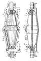
- Fig. 1 shows a cable 1 and a second cable 2 each having three cores 3, 4, 5. These cores 3,4, 5 are connected to each other with coupling elements 6, 7, and spacers 9 while maintaining a desired mutual distance.
- Cables 1, 2 are accommodated in openings 10 in the end zone of an inner socket coupling 11.
- In each of these end zones are in addition located two circumferential recesses 12, 13 which open to openings 10.
- circumferential recesses 12, 13 are filled up with injected binary material which has formed polyurethane in cured state.
- the rings of polyurethane thus formed seal against field formation control funnels 24 of conducting rubber. This ensures a liquid tight sealing. This ensures as a result that no moisture from outside can permeate into the interior of inner socket coupling 11 and that insulating oil present in the socket coupling cannot penetrate to the outside.
- the left end zone of inner socket coupling 11 also has two circumferential recesses 12, 13. These are in open communication with the circumferential recesses 12, 13 of the right end zone via a connecting channel 15.
- circumferential recesses 12, 13 connect channels 16 whereby plastic can be injected by means of a funnel 17 into recesses 12, 13 of the left end zone, which plastic can also fill circumferential recesses 12, 13 of the right end zone via connecting channel 15. As soon as outflow of plastic from channel 16 of the right end zone is observed, all the recesses 12, 13 are filled.
- the plastic is of the type that cures quickly.
- Fig. 2 shows an inner socket coupling filled with insulating oil with a part 19 of a divisible outer socket coupling.
- fig. 3 shows by way of example how heating to the desired temperature can be effected.
- a container 20 in which the lower part 19 of the outer socket coupling can rest, which container 20 can be covered by a cover 21 to form a housing.
- Into this housing 21 can be admitted hot air via a feed pipe 22, which air can, through the use of separating partition 28, circulate around the lower part of inner socket coupling 11 and half outer socket coupling 19 placed therein for heating of the binary material in circumferential recesses 12, 13 thereby causing it to cure.
- the hot air can flow out again via a discharge line 23.
- container 20 and cover 21 can be removed and inner socket coupling 11 and outer socket coupling 19 can be completed in a manner that is not drawn, after which the socket coupling can be finished in the usual way.
- an inner socket coupling of the type drawn and described with reference to the drawing is further filled with insulating oil.
- the method according to the invention must in this case be performed such that, after the injection of the plastic for the formation of the liquid tight sealing in the end zones, inner socket coupling 11 is filled with the insulating oil via the filling aperture that can be closed off by a screw cap 25. Cap 25 is afterwards fitted as according to fig. 2. Finally, onto the lower part 19 of the outer socket coupling is placed a corresponding upper part 27 (see fig. 1).
- resistance material resistance wire or a semi-conducting covering layer
- the method according to the invention can be applied for the end zones of an inner socket coupling, an outer socket coupling, both socket couplings and/or the area between both socket couplings.
Landscapes
- Processing Of Terminals (AREA)
- Cable Accessories (AREA)
Claims (3)
Applications Claiming Priority (2)
| Application Number | Priority Date | Filing Date | Title |
|---|---|---|---|
| NL8501016 | 1985-04-04 | ||
| NL8501016A NL8501016A (nl) | 1985-04-04 | 1985-04-04 | Werkwijze voor het door middel van een mof waterdicht met elkaar koppelen van elektrische kabels, alsmede mof voor toepassing van een dergelijke werkwijze. |
Publications (2)
| Publication Number | Publication Date |
|---|---|
| EP0197606A1 EP0197606A1 (de) | 1986-10-15 |
| EP0197606B1 true EP0197606B1 (de) | 1990-07-18 |
Family
ID=19845796
Family Applications (1)
| Application Number | Title | Priority Date | Filing Date |
|---|---|---|---|
| EP19860200557 Expired EP0197606B1 (de) | 1985-04-04 | 1986-04-02 | Verfahren zum wasserdichten Verbinden von elektrischen Kabeln mittels einer Muffe |
Country Status (3)
| Country | Link |
|---|---|
| EP (1) | EP0197606B1 (de) |
| DE (1) | DE3672650D1 (de) |
| NL (1) | NL8501016A (de) |
Families Citing this family (1)
| Publication number | Priority date | Publication date | Assignee | Title |
|---|---|---|---|---|
| NL8800832A (nl) * | 1988-03-31 | 1989-10-16 | Lovink Terborg Bv | Werkwijze voor het tegen vochtinvloeden beveiligen van door een huis omsloten elementen, alsmede vulmassa ten gebruike bij die werkwijze. |
Family Cites Families (3)
| Publication number | Priority date | Publication date | Assignee | Title |
|---|---|---|---|---|
| DE1465562A1 (de) * | 1964-09-25 | 1969-04-24 | Felten & Guilleaume Carlswerk | Kabel-Muffe oder -Endverschluss |
| DE1924181A1 (de) * | 1969-05-12 | 1970-11-19 | Siemens Ag | Kabelgarnitur aus Kunststoff zur Verbindung mit kunststoffummantelten Kabeln |
| NL170074C (nl) * | 1977-04-18 | 1982-09-16 | Ijzergieterij Lovink Bv | Verbinding tussen twee elektrische sterkstroomkabels. |
-
1985
- 1985-04-04 NL NL8501016A patent/NL8501016A/nl not_active Application Discontinuation
-
1986
- 1986-04-02 EP EP19860200557 patent/EP0197606B1/de not_active Expired
- 1986-04-02 DE DE8686200557T patent/DE3672650D1/de not_active Expired - Lifetime
Also Published As
| Publication number | Publication date |
|---|---|
| EP0197606A1 (de) | 1986-10-15 |
| DE3672650D1 (de) | 1990-08-23 |
| NL8501016A (nl) | 1986-11-03 |
Similar Documents
| Publication | Publication Date | Title |
|---|---|---|
| US4032214A (en) | Cable-termination assemblies and methods for manufacturing such assemblies | |
| US4322573A (en) | Encapsulation of telecommunications cable splices | |
| US4528419A (en) | Forming of cable splice closures | |
| JPH0159467B2 (de) | ||
| US11843232B2 (en) | Assembly and method for sealing a bundle of wires | |
| GB2104736A (en) | Connecting and sealing electric cables in an aperture in a housing | |
| US2247671A (en) | Cable seal | |
| EP0335430B1 (de) | Verfahren zum Schützen von in einem Gehäuse eingeschlossenen Elementen gegen Feuchtigkeitseinfluss | |
| CA1112346A (en) | Method of encapsulation | |
| US3209069A (en) | Joint enclosure for joined electric cables | |
| US3880557A (en) | Molding apparatus for splicing electrical cable | |
| US3328512A (en) | Electrical cable assemblies | |
| US4615114A (en) | Method of manufacturing molded buswork for power distribution systems | |
| US2987570A (en) | Fluid-tight connector structure for submersible apparatus | |
| EP0197606A1 (de) | Verfahren zum wasserdichten Verbinden von elektrischen Kabeln mittels einer Muffe | |
| US2636137A (en) | Dynamoelectric apparatus and method of making the same | |
| US3122597A (en) | Method of sealing joints in plastic coated electrical cables | |
| US3970735A (en) | Molding method for splicing electrical cable | |
| AU619364B2 (en) | Cable jointing | |
| US2310423A (en) | Means for preventing leakage of fluid through electric cables | |
| US2923762A (en) | Cable joint construction | |
| GB2046030A (en) | Sleeve assembly for sealing a joint between two cable ends | |
| US4500747A (en) | Gas pressurizable cable with compressed plug seal and method of making it | |
| US3795757A (en) | Distribution cable with permanently connected branch cables and method of effecting said connections | |
| CA1202388A (en) | Forming cable splice closures |
Legal Events
| Date | Code | Title | Description |
|---|---|---|---|
| PUAI | Public reference made under article 153(3) epc to a published international application that has entered the european phase |
Free format text: ORIGINAL CODE: 0009012 |
|
| AK | Designated contracting states |
Kind code of ref document: A1 Designated state(s): BE DE FR GB NL |
|
| 17P | Request for examination filed |
Effective date: 19861126 |
|
| 17Q | First examination report despatched |
Effective date: 19881004 |
|
| GRAA | (expected) grant |
Free format text: ORIGINAL CODE: 0009210 |
|
| AK | Designated contracting states |
Kind code of ref document: B1 Designated state(s): BE DE FR GB NL |
|
| REF | Corresponds to: |
Ref document number: 3672650 Country of ref document: DE Date of ref document: 19900823 |
|
| ET | Fr: translation filed | ||
| PLBE | No opposition filed within time limit |
Free format text: ORIGINAL CODE: 0009261 |
|
| STAA | Information on the status of an ep patent application or granted ep patent |
Free format text: STATUS: NO OPPOSITION FILED WITHIN TIME LIMIT |
|
| 26N | No opposition filed | ||
| REG | Reference to a national code |
Ref country code: GB Ref legal event code: IF02 |
|
| PGFP | Annual fee paid to national office [announced via postgrant information from national office to epo] |
Ref country code: GB Payment date: 20050411 Year of fee payment: 20 |
|
| PGFP | Annual fee paid to national office [announced via postgrant information from national office to epo] |
Ref country code: BE Payment date: 20050428 Year of fee payment: 20 |
|
| PGFP | Annual fee paid to national office [announced via postgrant information from national office to epo] |
Ref country code: NL Payment date: 20050429 Year of fee payment: 20 Ref country code: FR Payment date: 20050429 Year of fee payment: 20 |
|
| PGFP | Annual fee paid to national office [announced via postgrant information from national office to epo] |
Ref country code: DE Payment date: 20050502 Year of fee payment: 20 |
|
| PG25 | Lapsed in a contracting state [announced via postgrant information from national office to epo] |
Ref country code: GB Free format text: LAPSE BECAUSE OF EXPIRATION OF PROTECTION Effective date: 20060401 |
|
| PG25 | Lapsed in a contracting state [announced via postgrant information from national office to epo] |
Ref country code: NL Free format text: LAPSE BECAUSE OF EXPIRATION OF PROTECTION Effective date: 20060402 |
|
| REG | Reference to a national code |
Ref country code: GB Ref legal event code: PE20 |
|
| NLV7 | Nl: ceased due to reaching the maximum lifetime of a patent |
Effective date: 20060402 |
|
| BE20 | Be: patent expired |
Owner name: *LOVINK TERBORG B.V. Effective date: 20060402 |