EP0197620A2 - Cylinder locking device - Google Patents
Cylinder locking device Download PDFInfo
- Publication number
- EP0197620A2 EP0197620A2 EP86300228A EP86300228A EP0197620A2 EP 0197620 A2 EP0197620 A2 EP 0197620A2 EP 86300228 A EP86300228 A EP 86300228A EP 86300228 A EP86300228 A EP 86300228A EP 0197620 A2 EP0197620 A2 EP 0197620A2
- Authority
- EP
- European Patent Office
- Prior art keywords
- brake members
- piston rod
- cylinder
- members
- locking device
- Prior art date
- Legal status (The legal status is an assumption and is not a legal conclusion. Google has not performed a legal analysis and makes no representation as to the accuracy of the status listed.)
- Granted
Links
Images
Classifications
-
- F—MECHANICAL ENGINEERING; LIGHTING; HEATING; WEAPONS; BLASTING
- F15—FLUID-PRESSURE ACTUATORS; HYDRAULICS OR PNEUMATICS IN GENERAL
- F15B—SYSTEMS ACTING BY MEANS OF FLUIDS IN GENERAL; FLUID-PRESSURE ACTUATORS, e.g. SERVOMOTORS; DETAILS OF FLUID-PRESSURE SYSTEMS, NOT OTHERWISE PROVIDED FOR
- F15B15/00—Fluid-actuated devices for displacing a member from one position to another; Gearing associated therewith
- F15B15/20—Other details, e.g. assembly with regulating devices
- F15B15/26—Locking mechanisms
-
- F—MECHANICAL ENGINEERING; LIGHTING; HEATING; WEAPONS; BLASTING
- F15—FLUID-PRESSURE ACTUATORS; HYDRAULICS OR PNEUMATICS IN GENERAL
- F15B—SYSTEMS ACTING BY MEANS OF FLUIDS IN GENERAL; FLUID-PRESSURE ACTUATORS, e.g. SERVOMOTORS; DETAILS OF FLUID-PRESSURE SYSTEMS, NOT OTHERWISE PROVIDED FOR
- F15B15/00—Fluid-actuated devices for displacing a member from one position to another; Gearing associated therewith
- F15B15/20—Other details, e.g. assembly with regulating devices
- F15B15/26—Locking mechanisms
- F15B15/262—Locking mechanisms using friction, e.g. brake pads
Definitions
- the invention relates to a cylinder locking device for locking the piston rod of a fluid pressure cylinder at an arbitrary position, and more specifically to a cylinder locking device which can lock the piston rod automatically and securely in the event of a fault in a fluid pressure source.
- the present inventors have already proposed in Japanese patent application NO. 192272/1982 a cylinder locking device of a simple mechanical type which enables the piston rod of a fluid pressure cylinder to be securely locked at an arbitrary position.
- a thick-walled cylinder having outer and inner circumferential surfaces in eccentric relation, is divided in two in the region of maximum thickness and the region of minimum thickness in the axial direction to form two thick semi-cylindrical brake members, and the piston rod of a fluid pressure cylinder is slidably fitted within the inner circumferential portion of the two semi-cylindrical brake members, these brake members being rotatably fitted in a housing, and the two brake members being rotatable in opposite directions to each other whereby to lock the piston rod therebetween.
- the cylinder locking device as described above can lock the piston rod using a relatively small force and without producing shearing or rotational forces on the piston rod.
- a mechanism to operate the semi-cylindrical brake members automatically is required and so far no such mechanism has been available.
- an object of the present invention is to provide a cylinder locking device which can lock the piston rod of a fluid pressure cylinder automatically and which will reliably and safely lock the piston rod in the even that a fluid pressure source or a power source is turned off for any reason.
- a locking device for the piston of a fluid pressure cylinder comprising two nearly semi-cylindrical brake members formed in effect from a thick-walled cylinder, whose outer and inner circumferential surfaces are in eccentric relation, and which is divided in two in the axial direction in the regions of maximum and minimum thickness of the cylinder, and support members for rotatably supporting outer peripheral portions of the two brake members, with a piston rod of the fluid pressure cylinder slidably fitted within the inner circumferential portions of the brake members, such that said piston rod can be locked by relative angular displacement of the two brake members in opposite directions, characterized by a spring which is arranged to bias the two brake members in a direction to lock the piston rod, and an actuator for selectively rotating the brake members against the biasing force of the spring in a direction to release the locking action of the brake members on the piston rod.
- the fluid pressure cylinder of Fig. 1 comprises a cylinder tube or wall 1, a cylinder head 2 and a cylinder cover 3, tightened and fixed at both ends of the cylinder tube 1 by one or more tie rods (not shown), a piston 4 fitted within the cylinder tube 1, and a piston rod 5 passing through the centre of the cylinder cover 3 and fixed at its base end to the piston 4.
- a cylinder locking device is installed on the cylinder cover 3 and surrounds the outer circumference of the piston rod 5.
- Numerals 6 and 7 designate nearly semi-cylindrical brake members arranged to embrace an outer circumferential portion of the piston rod 5.
- the brake members 6, 7 are formed by taking a thick-walled cylinder which is arranged to have outer and inner circumferences which are in eccentric relation and dividing this cylinder into two about an axial plane which passes through the maximum thickness portion and the minimum thickness portion of the cylinder.
- the two axial ends of both outer circumferential portions of the brake members 6, 7 are rotatably supported by support members 8, 9, respectively.
- the support member 8 serves also as a housing on one end of the cylinder cover 3.
- the piston rod 5 passes through the centre of the support member 8, a bearing metal being positioned at the support region.
- the support member 9 includes a bearing metal fitted to the inside of a housing 10, an end portion of the housing 10 slidably supporting the piston rod 5.
- Bushes 11 made of fluororesin as its starting material are interposed at the positions where the support members 8,9 rotatably support the brake members 6,7, whereby to decrease the sliding friction.
- the nearly semi-cylindrical brake members 6, 7 have a respective circumferential space between each pair of opposing regions so that both members 6, 7 can be mutually rotated to some extent.
- the centre of the circle including the outer circumference of the brake members 6, 7 is shifted slightly downwards relative to the centre of the inner circumference thereof, i.e. relative to the central axis of the piston rod 5. Consequently, when the brake members 6, 7 are rotated in a direction to open the lower portion thereof as directed by the arrows in F ig. 2, the brake members 6, 7 are rotated in the support members 8, 9 for the outer circumference thereof and the piston rod 5 within the members 8, 9 is gripped from both sides and locked.
- Brackets 12, 13 having an L-shaped cross-section are fixed to lower portions of the two brake members 6, 7 and a coil spring 14 for biasing the brackets 12, 13 apar ishooked in a compressed state between the brackets 12, 13.
- the brake members 6, 7 are normally biased by the coil spring 14 into their position in which they lock the piston rod 5.
- a fluid pressure actuator 20 is arranged between the two arms 15, 16 and is fixed to a mounting plate 17 mounted on an upper portion of the housing 10.
- the fluid pressure actuator 20 comprises a cylinder 21, two pistons 22, 23 spaced from each other and fitted inside the cylinder 21, and pressure projections 24, 25 located on the outside of the two pistons 22, 23 for pushing the two arms 15, 16 apart.
- the fluid pressure actuator 20 is energised to hold the upper portions of the arms 15, 16 apart whereby the brake members 6, 7 are in the non-braking state.
- both pistons 22, 23 are moved outwards so as to urge the upper portions of the arms 15, 16 apart by way of the projections 24, 25.
- the two brake members 6, 7, whose outer circumferential portion is supported in the support members 8, 9, and thus rotated against the biasing force of the coil springs 14 so as to open the circumferential gap between the uppers portions of the brake members and to close the circumferential gap between the lower portions of. those members.
- the piston rod 5 Since the centre of the inner cirumference of the support members 8, 9, i.e., the centre the circle including the outer circumference of the brake members 6, 7, is shifted from the centre of the inner circumference of the brake members 6, 7, i.e., the centre of the circular section of the piston rod 5, the piston rod 5 is graspsed by the brake members 6, 7 from both sides and thereby locked. The piston rod 5 can thus be locked without being subjected to shearing or rotational forces.
- an electromagnetic actuator may be used in place of the fluid pressure actuator 20.
- the piston rod since the piston rod is grapsed by the two nearly semi-cylinderical brake members, it can. be locked by a mechanical brake of simple structure without producing shearing or rotational forces, whereby the piston rod or the bearing parts therefor is prevented from deformation or abrasion and the piston rod can be stopped securely and reliably. Furthermore, since the brake members are normally biased in the locking direction by the spring, even if the fluid pressure source or the power source of the actuator is suddenly turned off as a result of a fault, the piston rod is immediately locked by the biasing force of the spring and safety is secured.
Landscapes
- Engineering & Computer Science (AREA)
- Physics & Mathematics (AREA)
- Fluid Mechanics (AREA)
- Mechanical Engineering (AREA)
- General Engineering & Computer Science (AREA)
- Actuator (AREA)
- Braking Arrangements (AREA)
Abstract
Description
- The invention relates to a cylinder locking device for locking the piston rod of a fluid pressure cylinder at an arbitrary position, and more specifically to a cylinder locking device which can lock the piston rod automatically and securely in the event of a fault in a fluid pressure source.
- The present inventors have already proposed in Japanese patent application NO. 192272/1982 a cylinder locking device of a simple mechanical type which enables the piston rod of a fluid pressure cylinder to be securely locked at an arbitrary position.
- In the latter cylinder locking device, a thick-walled cylinder, having outer and inner circumferential surfaces in eccentric relation, is divided in two in the region of maximum thickness and the region of minimum thickness in the axial direction to form two thick semi-cylindrical brake members, and the piston rod of a fluid pressure cylinder is slidably fitted within the inner circumferential portion of the two semi-cylindrical brake members, these brake members being rotatably fitted in a housing, and the two brake members being rotatable in opposite directions to each other whereby to lock the piston rod therebetween.
- The cylinder locking device as described above can lock the piston rod using a relatively small force and without producing shearing or rotational forces on the piston rod. In order for the device to be useful widely in practice, however, a mechanism to operate the semi-cylindrical brake members automatically is required and so far no such mechanism has been available.
- In order to increase the utility of the above-described cylinder locking device, an object of the present invention is to provide a cylinder locking device which can lock the piston rod of a fluid pressure cylinder automatically and which will reliably and safely lock the piston rod in the even that a fluid pressure source or a power source is turned off for any reason.
- In accordance with the present invention, there is provided a locking device for the piston of a fluid pressure cylinder, comprising two nearly semi-cylindrical brake members formed in effect from a thick-walled cylinder, whose outer and inner circumferential surfaces are in eccentric relation, and which is divided in two in the axial direction in the regions of maximum and minimum thickness of the cylinder, and support members for rotatably supporting outer peripheral portions of the two brake members, with a piston rod of the fluid pressure cylinder slidably fitted within the inner circumferential portions of the brake members, such that said piston rod can be locked by relative angular displacement of the two brake members in opposite directions, characterized by a spring which is arranged to bias the two brake members in a direction to lock the piston rod, and an actuator for selectively rotating the brake members against the biasing force of the spring in a direction to release the locking action of the brake members on the piston rod.
- The invention is described further hereinafter, by way of example only, with reference to the accompanying drawings, wherein:
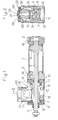
- Fig. 1 is a sectional side view of one embodiment of a cylinder locking device in accordance with the present invention installed to a fluid pressure cylinder; and
- Fig. 2 is a sectional end view taken on the line II-II in Fig. 1.
- The fluid pressure cylinder of Fig. 1 comprises a cylinder tube or wall 1, a cylinder head 2 and a
cylinder cover 3, tightened and fixed at both ends of the cylinder tube 1 by one or more tie rods (not shown), apiston 4 fitted within the cylinder tube 1, and apiston rod 5 passing through the centre of thecylinder cover 3 and fixed at its base end to thepiston 4. A cylinder locking device is installed on thecylinder cover 3 and surrounds the outer circumference of thepiston rod 5.Numerals piston rod 5. - The
brake members brake members support members 8, 9, respectively. Thesupport member 8 serves also as a housing on one end of thecylinder cover 3. Thepiston rod 5 passes through the centre of thesupport member 8, a bearing metal being positioned at the support region. The support member 9 includes a bearing metal fitted to the inside of ahousing 10, an end portion of thehousing 10 slidably supporting thepiston rod 5. Bushes 11 made of fluororesin as its starting material are interposed at the positions where thesupport members 8,9 rotatably support thebrake members semi-cylindrical brake members members brake members piston rod 5. Consequently, when thebrake members brake members support members 8, 9 for the outer circumference thereof and thepiston rod 5 within themembers 8, 9 is gripped from both sides and locked. -
Brackets brake members coil spring 14 for biasing thebrackets brackets brake members coil spring 14 into their position in which they lock thepiston rod 5. - Further L-
shaped arms brake members fluid pressure actuator 20 is arranged between the twoarms mounting plate 17 mounted on an upper portion of thehousing 10. Thefluid pressure actuator 20 comprises acylinder 21, twopistons cylinder 21, andpressure projections pistons arms pistons arms brake members piston rod 5. - Operation of the above-described cylinder locking device is as follows.
- In normal operation, the
piston 4 of the fluid pressure cylinder, and with it thepiston rod 5, can be moved to the left in Fig. l.by fluid pressure supplied via aport 18. Movement of the piston andpiston rod 5 to the right is obtained by fluid pressure supplied via aport 19. - In the operating state of the
piston rod 5 shown in Fig. 2, thefluid pressure actuator 20 is energised to hold the upper portions of thearms brake members port 26 of thefluid pressure actuator 20, bothpistons arms projections brake members support members 8, 9, and thus rotated against the biasing force of thecoil springs 14 so as to open the circumferential gap between the uppers portions of the brake members and to close the circumferential gap between the lower portions of. those members. - Since the centre of the circle which includes the outer circumference of the
brake members piston rod 5, a small gap is produced between.thebrake members piston rod 5 and the brake is thereby released. - On the other hand, if the fluid pressure applied to the
fluid pressure actuator 20 is decreased, either delibrately in order to effect locking of thepiston rod 5 or as a result of a fault, thebrake members piston rod 5 automatically. In other words, if fluid pressure within thefluid pressure actuator 20 is removed for any reason, the force necessary to push thepistons coil spring 14 acting on thebrake members support members 8, 9 so that the circumferential gap between the upper portions of thebrake members support members 8, 9, i.e., the centre the circle including the outer circumference of thebrake members brake members piston rod 5, thepiston rod 5 is graspsed by thebrake members piston rod 5 can thus be locked without being subjected to shearing or rotational forces. - As an alternative, an electromagnetic actuator may be used in place of the
fluid pressure actuator 20. - According to the cylinder locking device of the invention described above, since the piston rod is grapsed by the two nearly semi-cylinderical brake members, it can. be locked by a mechanical brake of simple structure without producing shearing or rotational forces, whereby the piston rod or the bearing parts therefor is prevented from deformation or abrasion and the piston rod can be stopped securely and reliably. Furthermore, since the brake members are normally biased in the locking direction by the spring, even if the fluid pressure source or the power source of the actuator is suddenly turned off as a result of a fault, the piston rod is immediately locked by the biasing force of the spring and safety is secured.
Claims (4)
Applications Claiming Priority (2)
| Application Number | Priority Date | Filing Date | Title |
|---|---|---|---|
| JP74674/85 | 1985-04-09 | ||
| JP60074674A JPS61233209A (en) | 1985-04-09 | 1985-04-09 | Cylinder stopping apparatus |
Publications (3)
| Publication Number | Publication Date |
|---|---|
| EP0197620A2 true EP0197620A2 (en) | 1986-10-15 |
| EP0197620A3 EP0197620A3 (en) | 1987-04-01 |
| EP0197620B1 EP0197620B1 (en) | 1989-03-22 |
Family
ID=13554007
Family Applications (1)
| Application Number | Title | Priority Date | Filing Date |
|---|---|---|---|
| EP86300228A Expired EP0197620B1 (en) | 1985-04-09 | 1986-01-15 | Cylinder locking device |
Country Status (4)
| Country | Link |
|---|---|
| EP (1) | EP0197620B1 (en) |
| JP (1) | JPS61233209A (en) |
| KR (1) | KR920004066B1 (en) |
| DE (1) | DE3662548D1 (en) |
Cited By (5)
| Publication number | Priority date | Publication date | Assignee | Title |
|---|---|---|---|---|
| DE3744295A1 (en) * | 1987-12-28 | 1989-07-13 | Kontec Gmbh | Clamping device for the firm clamping of a linearly movable rod |
| EP0446694A1 (en) * | 1990-03-14 | 1991-09-18 | UNIVER S.p.A. | Locking device for pneumatic cylinders |
| DE19543471C1 (en) * | 1995-11-22 | 1997-01-09 | Festo Kg | Clamping unit |
| WO2000074892A3 (en) * | 1999-06-07 | 2002-10-31 | Frenotech Establishment | Locking device |
| DE19934750B4 (en) * | 1999-06-07 | 2010-03-11 | Frenotech Establishment | Locking device |
Families Citing this family (6)
| Publication number | Priority date | Publication date | Assignee | Title |
|---|---|---|---|---|
| JP2597150B2 (en) * | 1988-06-23 | 1997-04-02 | 明男 松井 | Cylinder stop device |
| JP4150993B2 (en) * | 2000-04-12 | 2008-09-17 | Smc株式会社 | Swing actuator |
| KR20020016669A (en) * | 2000-08-26 | 2002-03-06 | 배길훈 | parking brake using rear hub bearing stem |
| JP4826764B2 (en) * | 2006-05-17 | 2011-11-30 | 株式会社パボット技研 | Linear rod stop device |
| JP4965338B2 (en) * | 2007-05-23 | 2012-07-04 | 株式会社アイ・アンド・ティー | Shaft brake device |
| JP5009106B2 (en) * | 2007-09-12 | 2012-08-22 | 株式会社アイ・アンド・ティー | Braking device for linear motion body |
Family Cites Families (3)
| Publication number | Priority date | Publication date | Assignee | Title |
|---|---|---|---|---|
| US3554094A (en) * | 1969-02-20 | 1971-01-12 | Bell Aerospace Corp | Piston rod locking mechanism |
| DE2552994A1 (en) * | 1975-11-26 | 1977-06-02 | Gatermann Ingenieurbuero Gmbh | Braking for axial motion of jack piston shaft - involves use of eccentric disc surrounding shaft activated by piston shafts (SW081176) |
| US4214795A (en) * | 1977-11-25 | 1980-07-29 | Shoketsu Kinzoku Kogyo Kabushiki Kaisha | Piston braking device for hydraulic or pneumatic cylinders |
-
1985
- 1985-04-09 JP JP60074674A patent/JPS61233209A/en active Pending
- 1985-12-11 KR KR1019850009317A patent/KR920004066B1/en not_active Expired
-
1986
- 1986-01-15 DE DE8686300228T patent/DE3662548D1/en not_active Expired
- 1986-01-15 EP EP86300228A patent/EP0197620B1/en not_active Expired
Cited By (6)
| Publication number | Priority date | Publication date | Assignee | Title |
|---|---|---|---|---|
| DE3744295A1 (en) * | 1987-12-28 | 1989-07-13 | Kontec Gmbh | Clamping device for the firm clamping of a linearly movable rod |
| EP0446694A1 (en) * | 1990-03-14 | 1991-09-18 | UNIVER S.p.A. | Locking device for pneumatic cylinders |
| DE19543471C1 (en) * | 1995-11-22 | 1997-01-09 | Festo Kg | Clamping unit |
| FR2741406A1 (en) * | 1995-11-22 | 1997-05-23 | Festo Kg | CLAMPING UNIT FOR THE IMMOBILIZATION OF AN AXIALLY MOBILE ROD |
| WO2000074892A3 (en) * | 1999-06-07 | 2002-10-31 | Frenotech Establishment | Locking device |
| DE19934750B4 (en) * | 1999-06-07 | 2010-03-11 | Frenotech Establishment | Locking device |
Also Published As
| Publication number | Publication date |
|---|---|
| EP0197620A3 (en) | 1987-04-01 |
| KR920004066B1 (en) | 1992-05-23 |
| DE3662548D1 (en) | 1989-04-27 |
| EP0197620B1 (en) | 1989-03-22 |
| JPS61233209A (en) | 1986-10-17 |
| KR860008379A (en) | 1986-11-15 |
Similar Documents
| Publication | Publication Date | Title |
|---|---|---|
| EP0197620A2 (en) | Cylinder locking device | |
| KR0158896B1 (en) | Disc brake for vehicles especially road vehicles | |
| US5433298A (en) | Actuating mechanism for a sliding-caliper disc brake | |
| US5236396A (en) | Friction device, in particular for belt tensioners | |
| EP0124335B1 (en) | Force motor with null centering and null position bias | |
| JP2000514162A (en) | Electromagnetically releasable friction safety brake | |
| KR930012553A (en) | Elevator drive system and brake assembly associated with it | |
| KR100234789B1 (en) | S-cam for drum brake | |
| JPH0366538B2 (en) | ||
| JPS63101531A (en) | Disk-brake for car | |
| JPH10148265A (en) | Rotary valve assembly | |
| JPH0424579B2 (en) | ||
| US4693341A (en) | Disc brake for automotive vehicles | |
| US4257500A (en) | Hand drive for coupling to a rotatable shaft | |
| US3983971A (en) | Brake device | |
| US3435691A (en) | Means for actuating a friction pad in a disc brake | |
| US2368317A (en) | Motor brake adjusting means | |
| US2966240A (en) | Automatic brake | |
| US4567968A (en) | Locking element for disc brake with sliding caliper and disc brake comprising such a locking element | |
| US5388670A (en) | Wear-limit warning anti-rattle spring | |
| US3288255A (en) | Rotary motion control apparatus and safety release | |
| US4757888A (en) | Electro magnetic clutch with a rotation detector for a refrigerant compressor | |
| US6467587B2 (en) | Energy absorbing shock mechanism for reducing impact and rotary actuator incorporating same | |
| US3265165A (en) | Brake shoe mounting | |
| US3237735A (en) | Irreversible drive |
Legal Events
| Date | Code | Title | Description |
|---|---|---|---|
| PUAI | Public reference made under article 153(3) epc to a published international application that has entered the european phase |
Free format text: ORIGINAL CODE: 0009012 |
|
| AK | Designated contracting states |
Kind code of ref document: A2 Designated state(s): CH DE FR GB IT LI NL |
|
| PUAL | Search report despatched |
Free format text: ORIGINAL CODE: 0009013 |
|
| AK | Designated contracting states |
Kind code of ref document: A3 Designated state(s): CH DE FR GB IT LI NL |
|
| 17P | Request for examination filed |
Effective date: 19870513 |
|
| 17Q | First examination report despatched |
Effective date: 19871215 |
|
| GRAA | (expected) grant |
Free format text: ORIGINAL CODE: 0009210 |
|
| AK | Designated contracting states |
Kind code of ref document: B1 Designated state(s): CH DE FR GB IT LI NL |
|
| ITF | It: translation for a ep patent filed | ||
| REF | Corresponds to: |
Ref document number: 3662548 Country of ref document: DE Date of ref document: 19890427 |
|
| ET | Fr: translation filed | ||
| PLBE | No opposition filed within time limit |
Free format text: ORIGINAL CODE: 0009261 |
|
| STAA | Information on the status of an ep patent application or granted ep patent |
Free format text: STATUS: NO OPPOSITION FILED WITHIN TIME LIMIT |
|
| 26N | No opposition filed | ||
| ITTA | It: last paid annual fee | ||
| PGFP | Annual fee paid to national office [announced via postgrant information from national office to epo] |
Ref country code: GB Payment date: 19970106 Year of fee payment: 12 |
|
| PGFP | Annual fee paid to national office [announced via postgrant information from national office to epo] |
Ref country code: FR Payment date: 19970109 Year of fee payment: 12 |
|
| PGFP | Annual fee paid to national office [announced via postgrant information from national office to epo] |
Ref country code: CH Payment date: 19970121 Year of fee payment: 12 |
|
| PGFP | Annual fee paid to national office [announced via postgrant information from national office to epo] |
Ref country code: NL Payment date: 19970130 Year of fee payment: 12 |
|
| PG25 | Lapsed in a contracting state [announced via postgrant information from national office to epo] |
Ref country code: GB Free format text: LAPSE BECAUSE OF NON-PAYMENT OF DUE FEES Effective date: 19980115 |
|
| PG25 | Lapsed in a contracting state [announced via postgrant information from national office to epo] |
Ref country code: LI Free format text: LAPSE BECAUSE OF NON-PAYMENT OF DUE FEES Effective date: 19980131 Ref country code: FR Free format text: THE PATENT HAS BEEN ANNULLED BY A DECISION OF A NATIONAL AUTHORITY Effective date: 19980131 Ref country code: CH Free format text: LAPSE BECAUSE OF NON-PAYMENT OF DUE FEES Effective date: 19980131 |
|
| PG25 | Lapsed in a contracting state [announced via postgrant information from national office to epo] |
Ref country code: NL Free format text: LAPSE BECAUSE OF NON-PAYMENT OF DUE FEES Effective date: 19980801 |
|
| GBPC | Gb: european patent ceased through non-payment of renewal fee |
Effective date: 19980115 |
|
| REG | Reference to a national code |
Ref country code: CH Ref legal event code: PL |
|
| NLV4 | Nl: lapsed or anulled due to non-payment of the annual fee |
Effective date: 19980801 |
|
| REG | Reference to a national code |
Ref country code: FR Ref legal event code: ST |
|
| PGFP | Annual fee paid to national office [announced via postgrant information from national office to epo] |
Ref country code: DE Payment date: 19991231 Year of fee payment: 15 |
|
| PG25 | Lapsed in a contracting state [announced via postgrant information from national office to epo] |
Ref country code: DE Free format text: LAPSE BECAUSE OF NON-PAYMENT OF DUE FEES Effective date: 20011101 |
|
| PG25 | Lapsed in a contracting state [announced via postgrant information from national office to epo] |
Ref country code: IT Free format text: LAPSE BECAUSE OF NON-PAYMENT OF DUE FEES;WARNING: LAPSES OF ITALIAN PATENTS WITH EFFECTIVE DATE BEFORE 2007 MAY HAVE OCCURRED AT ANY TIME BEFORE 2007. THE CORRECT EFFECTIVE DATE MAY BE DIFFERENT FROM THE ONE RECORDED. Effective date: 20050115 |