EP0197670A1 - Raccords pour tubes - Google Patents
Raccords pour tubes Download PDFInfo
- Publication number
- EP0197670A1 EP0197670A1 EP86301783A EP86301783A EP0197670A1 EP 0197670 A1 EP0197670 A1 EP 0197670A1 EP 86301783 A EP86301783 A EP 86301783A EP 86301783 A EP86301783 A EP 86301783A EP 0197670 A1 EP0197670 A1 EP 0197670A1
- Authority
- EP
- European Patent Office
- Prior art keywords
- throughway
- seal
- tube
- liner
- tube coupling
- Prior art date
- Legal status (The legal status is an assumption and is not a legal conclusion. Google has not performed a legal analysis and makes no representation as to the accuracy of the status listed.)
- Granted
Links
- 230000008878 coupling Effects 0.000 title claims abstract description 34
- 238000010168 coupling process Methods 0.000 title claims abstract description 34
- 238000005859 coupling reaction Methods 0.000 title claims abstract description 34
- 239000000463 material Substances 0.000 claims abstract description 26
- 239000012530 fluid Substances 0.000 claims abstract description 7
- -1 polyethylene Polymers 0.000 claims description 4
- 229920002379 silicone rubber Polymers 0.000 claims description 4
- 239000004698 Polyethylene Substances 0.000 claims description 3
- 238000001746 injection moulding Methods 0.000 claims description 3
- 229920000573 polyethylene Polymers 0.000 claims description 3
- 235000012206 bottled water Nutrition 0.000 description 4
- 239000003651 drinking water Substances 0.000 description 4
- 238000010438 heat treatment Methods 0.000 description 4
- 210000002105 tongue Anatomy 0.000 description 3
- DHKHKXVYLBGOIT-UHFFFAOYSA-N acetaldehyde Diethyl Acetal Natural products CCOC(C)OCC DHKHKXVYLBGOIT-UHFFFAOYSA-N 0.000 description 2
- 229920001577 copolymer Polymers 0.000 description 2
- 238000002347 injection Methods 0.000 description 2
- 239000007924 injection Substances 0.000 description 2
- 239000007788 liquid Substances 0.000 description 2
- XLYOFNOQVPJJNP-UHFFFAOYSA-N water Substances O XLYOFNOQVPJJNP-UHFFFAOYSA-N 0.000 description 2
- 229910001369 Brass Inorganic materials 0.000 description 1
- 229910001018 Cast iron Inorganic materials 0.000 description 1
- 239000002253 acid Substances 0.000 description 1
- 239000010951 brass Substances 0.000 description 1
- 230000006835 compression Effects 0.000 description 1
- 238000007906 compression Methods 0.000 description 1
- 238000010276 construction Methods 0.000 description 1
- 238000004519 manufacturing process Methods 0.000 description 1
- 239000002184 metal Substances 0.000 description 1
- 229910052751 metal Inorganic materials 0.000 description 1
- 239000000203 mixture Substances 0.000 description 1
- 230000004048 modification Effects 0.000 description 1
- 238000012986 modification Methods 0.000 description 1
- 238000007789 sealing Methods 0.000 description 1
Images

Classifications
-
- F—MECHANICAL ENGINEERING; LIGHTING; HEATING; WEAPONS; BLASTING
- F16—ENGINEERING ELEMENTS AND UNITS; GENERAL MEASURES FOR PRODUCING AND MAINTAINING EFFECTIVE FUNCTIONING OF MACHINES OR INSTALLATIONS; THERMAL INSULATION IN GENERAL
- F16L—PIPES; JOINTS OR FITTINGS FOR PIPES; SUPPORTS FOR PIPES, CABLES OR PROTECTIVE TUBING; MEANS FOR THERMAL INSULATION IN GENERAL
- F16L37/00—Couplings of the quick-acting type
- F16L37/08—Couplings of the quick-acting type in which the connection between abutting or axially overlapping ends is maintained by locking members
- F16L37/084—Couplings of the quick-acting type in which the connection between abutting or axially overlapping ends is maintained by locking members combined with automatic locking
- F16L37/092—Couplings of the quick-acting type in which the connection between abutting or axially overlapping ends is maintained by locking members combined with automatic locking by means of elements wedged between the pipe and the frusto-conical surface of the body of the connector
- F16L37/0925—Couplings of the quick-acting type in which the connection between abutting or axially overlapping ends is maintained by locking members combined with automatic locking by means of elements wedged between the pipe and the frusto-conical surface of the body of the connector with rings which bite into the wall of the pipe
-
- F—MECHANICAL ENGINEERING; LIGHTING; HEATING; WEAPONS; BLASTING
- F16—ENGINEERING ELEMENTS AND UNITS; GENERAL MEASURES FOR PRODUCING AND MAINTAINING EFFECTIVE FUNCTIONING OF MACHINES OR INSTALLATIONS; THERMAL INSULATION IN GENERAL
- F16L—PIPES; JOINTS OR FITTINGS FOR PIPES; SUPPORTS FOR PIPES, CABLES OR PROTECTIVE TUBING; MEANS FOR THERMAL INSULATION IN GENERAL
- F16L37/00—Couplings of the quick-acting type
- F16L37/08—Couplings of the quick-acting type in which the connection between abutting or axially overlapping ends is maintained by locking members
- F16L37/084—Couplings of the quick-acting type in which the connection between abutting or axially overlapping ends is maintained by locking members combined with automatic locking
- F16L37/092—Couplings of the quick-acting type in which the connection between abutting or axially overlapping ends is maintained by locking members combined with automatic locking by means of elements wedged between the pipe and the frusto-conical surface of the body of the connector
- F16L37/0927—Couplings of the quick-acting type in which the connection between abutting or axially overlapping ends is maintained by locking members combined with automatic locking by means of elements wedged between the pipe and the frusto-conical surface of the body of the connector the wedge element being axially displaceable for releasing the coupling
-
- F—MECHANICAL ENGINEERING; LIGHTING; HEATING; WEAPONS; BLASTING
- F16—ENGINEERING ELEMENTS AND UNITS; GENERAL MEASURES FOR PRODUCING AND MAINTAINING EFFECTIVE FUNCTIONING OF MACHINES OR INSTALLATIONS; THERMAL INSULATION IN GENERAL
- F16L—PIPES; JOINTS OR FITTINGS FOR PIPES; SUPPORTS FOR PIPES, CABLES OR PROTECTIVE TUBING; MEANS FOR THERMAL INSULATION IN GENERAL
- F16L58/00—Protection of pipes or pipe fittings against corrosion or incrustation
- F16L58/02—Protection of pipes or pipe fittings against corrosion or incrustation by means of internal or external coatings
- F16L58/04—Coatings characterised by the materials used
- F16L58/10—Coatings characterised by the materials used by rubber or plastics
- F16L58/1009—Coatings characterised by the materials used by rubber or plastics the coating being placed inside the pipe
- F16L58/1045—Coatings characterised by the materials used by rubber or plastics the coating being placed inside the pipe the coating being an extruded or a fused layer
-
- F—MECHANICAL ENGINEERING; LIGHTING; HEATING; WEAPONS; BLASTING
- F16—ENGINEERING ELEMENTS AND UNITS; GENERAL MEASURES FOR PRODUCING AND MAINTAINING EFFECTIVE FUNCTIONING OF MACHINES OR INSTALLATIONS; THERMAL INSULATION IN GENERAL
- F16L—PIPES; JOINTS OR FITTINGS FOR PIPES; SUPPORTS FOR PIPES, CABLES OR PROTECTIVE TUBING; MEANS FOR THERMAL INSULATION IN GENERAL
- F16L58/00—Protection of pipes or pipe fittings against corrosion or incrustation
- F16L58/18—Protection of pipes or pipe fittings against corrosion or incrustation specially adapted for pipe fittings
-
- Y—GENERAL TAGGING OF NEW TECHNOLOGICAL DEVELOPMENTS; GENERAL TAGGING OF CROSS-SECTIONAL TECHNOLOGIES SPANNING OVER SEVERAL SECTIONS OF THE IPC; TECHNICAL SUBJECTS COVERED BY FORMER USPC CROSS-REFERENCE ART COLLECTIONS [XRACs] AND DIGESTS
- Y10—TECHNICAL SUBJECTS COVERED BY FORMER USPC
- Y10S—TECHNICAL SUBJECTS COVERED BY FORMER USPC CROSS-REFERENCE ART COLLECTIONS [XRACs] AND DIGESTS
- Y10S285/00—Pipe joints or couplings
- Y10S285/918—O-ring
Definitions
- This invention relates to tube couplings and is particularly although not exclusively applicable to tube couplings for potable water and domestic heating appliances.
- This invention provides a tube coupling comprising a hollow body having a throughway to receive a tube from at least one end of the throughway, a releasable tube gripping device mounted in the throughway adjacent said one end, a seal encircling the throughway to seal with the outer periphery of the tube disposed adjacent the tube gripping device and a liner extending along the throughway from the seal and arranged with the seal to prevent fluid from the tube having direct contact with the wall of the hollow body, the seal and liner being formed from an inert material or materials.
- the invention thus permits a tube coupling to be formed with an outer body of an engineering type material such as, for example, acetal copolymer and with an inner liner and seal formed from polymethylene material or silicon rubber which can be injection moulded inside the outer body.
- an engineering type material such as, for example, acetal copolymer
- an inner liner and seal formed from polymethylene material or silicon rubber which can be injection moulded inside the outer body.
- a tube coupling wherein the throughway has an annular shoulder spaced along the throughway from said one end to provide a stop for engagement by an end of a tube inserted in the throughway from that end, the seal being disposed between the shoulder and the gripping device at the end of the throughway and the liner extending from the seal along the throughway and over the annular shoulder.
- the seal may be formed integrally with and from the same material as the liner or the seal may be a separate component from the liner and engage an end of the liner.
- the liner may comprise a polyethylene material or silicon rubber formed by injection moulding in the throughway.
- the hollow body may have a throughway intended to receive tubes from both ends thereof to couple the tubes together, the throughway having releasable tube gripping devices at both ends of the throughway and seals being provided adjacent both ends of the throughway with a liner extending between the seals, the liner and seals being formed from an inert material or materials and being arranged to prevent contact of fluid flowing through the tubes with the wall of the hollow body.
- the throughway may have an annular shoulder facing towards said one end thereof and against which the seal abuts to support the seal against movement along the throughway away from said one end.
- the side of the seal engaging said annular shoulder may be formed with a projecting annular tongue which engages in an annular recess in said shoulder to assist in supporting the seal in the throughway.
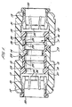
- a double-ended tube coupling for connecting two lengths of pipe (not shown) together and comprising an injection moulded acetal copolymer hollow generally tubular body 10 having a central throughway indicated at 11 and open ends 12 and 13.
- the body 10 has an integral annular wall 14 encircling the throughway to define a stop against which the ends of tubes inserted from either end of the throughway engage.
- each step Partway along the throughway from the annular wall 14 towards each end 12, 13 of the throughway the wall of the throughway is stepped out at 15, 16 to form enlarged bores 17, 18 extending towards the open ends 12, 13 of the throughway.
- the steps or shoulders 15, 16 thus formed in the bore face towards the open ends 12, 13 of the throughway and each step has an annular recess, 19, 20 again facing towards the open ends of the throughway.
- Annular resilient seals 21, 22, are formed in the enlarged bores 17, 18, against the shoulders 15,16 to seal with the outer surfaces of tubes inserted into the throughway.
- Each seal has a resilient tongue 23, 24 and the tongues engage in the recesses 19, 20 to assist in supporting the seal in position.
- the seals are formed integrally with a liner 25 which extends from seal to seal along the throughway and over the shoulder 14 midway along the throughway. Between the shoulder and each seal, the liner is formed with additional raised sealing ribs 26, 27 to engage the outer surfaces of the tube inserted in the throughway.
- the seal/liner are formed by injection moulding in the hollow body from polyethylene material or silicon rubber and the wall of the body is formed with bores 28, 29 on either side of the annular shoulder through which the material is injected in forming the seal/liner in the body.
- the material of the resilient seals and liner is inert to potable water or water used in domestic central heating systems.
- the throughway is formed with tapering cams 30,31 reducing towards the ends of the body and collets 32,33 are disposed in the ends of the body and have resilient fingers 34, 35 extending into the body and formed with metal insert grips pastway along the inner sides of the fingers for gripping a tube extending through the collet.
- the resilient fingers of the collets are compressed into engagement with the tubes extending through the collets by engagement with the outer sides of the resilient fingers with the cams 30,31 to hold the tubes in the throughway.
- the construction of: the tube coupling is generally as described and illustrated in our U.K. Patent Nos.1520742, 1573757, 2007322, 2051280 and 2052662 to which reference should be made.
- two tubes to be connected together are located in alignment to one another and the ends inserted in the coupling body through the collets, through the seals 21, 26 or 22, 27 and into engagement with the lined annular walls 14.
- the collets 32, 33 are pulled outwardly to force the resilient fingers of the collets into engagement with the tube surfaces and thereby lock the tubes in position.
- the seals 21, 26 and 22, 27 seal with the outer surfaces of the tube and thereby prevent loss of fluid from the coupling and, by virtue of the inert liner, the liquid flowing through the tube is prevented from coming into contact with any part of the outer body with which corrosive action could occur.
- Figures 2 shows a further embodiment of the invention which is generally similar to that described above except that the seals 21, 22 are formed separately from the liner 25 and may be of the same or of different material but in either case, would be formed from a material which is inert to the liquid to be conducted by the tubes connected by the coupling.
- the arrangement is otherwise similar to that described above.
Landscapes
- Engineering & Computer Science (AREA)
- General Engineering & Computer Science (AREA)
- Mechanical Engineering (AREA)
- Joints With Sleeves (AREA)
- Quick-Acting Or Multi-Walled Pipe Joints (AREA)
Applications Claiming Priority (2)
| Application Number | Priority Date | Filing Date | Title |
|---|---|---|---|
| GB8506317 | 1985-03-12 | ||
| GB8506317A GB2172356B (en) | 1985-03-12 | 1985-03-12 | Improvements in or relating to tube couplings |
Publications (2)
| Publication Number | Publication Date |
|---|---|
| EP0197670A1 true EP0197670A1 (fr) | 1986-10-15 |
| EP0197670B1 EP0197670B1 (fr) | 1989-08-23 |
Family
ID=10575836
Family Applications (1)
| Application Number | Title | Priority Date | Filing Date |
|---|---|---|---|
| EP86301783A Expired EP0197670B1 (fr) | 1985-03-12 | 1986-03-12 | Raccords pour tubes |
Country Status (5)
| Country | Link |
|---|---|
| US (1) | US4657286A (fr) |
| EP (1) | EP0197670B1 (fr) |
| JP (1) | JPS61223394A (fr) |
| DE (1) | DE3665211D1 (fr) |
| GB (1) | GB2172356B (fr) |
Cited By (2)
| Publication number | Priority date | Publication date | Assignee | Title |
|---|---|---|---|---|
| EP1710854A3 (fr) * | 2005-03-16 | 2007-10-03 | Jones, William E.M. | Connecteur pour système de réapprovisionnement en eau d'une batterie |
| EP2876345A1 (fr) * | 2013-11-22 | 2015-05-27 | Systemvertrieb Jäger GmbH Sanitär- und Heizungstechnik | Système de raccordement de tubes à fiches |
Families Citing this family (57)
| Publication number | Priority date | Publication date | Assignee | Title |
|---|---|---|---|---|
| EP0255368B1 (fr) * | 1986-07-30 | 1990-04-11 | John Derek Guest | Raccord pour tubes |
| GB9112617D0 (en) * | 1991-06-12 | 1991-07-31 | Guest John D | Improvements in or relating to tube coupling bodies |
| DE4139124C1 (fr) * | 1991-11-28 | 1993-04-01 | Rasmussen Gmbh, 6457 Maintal, De | |
| US5230539A (en) * | 1991-12-31 | 1993-07-27 | Dana Corporation | Quick connect tube coupling |
| GB9325432D0 (en) * | 1993-12-13 | 1994-02-16 | Guest John D | Improvements in or relating to seal arrangements |
| JPH09196269A (ja) * | 1996-01-19 | 1997-07-29 | Smc Corp | 管継手 |
| US5833276A (en) * | 1997-02-03 | 1998-11-10 | Etco Speciality Products, Inc. | Conduit doupling |
| AU2489899A (en) | 1998-01-29 | 1999-08-16 | Value Plastics, Inc. | An improved releasable collet type tube coupling system |
| GB2373303B (en) * | 2001-01-23 | 2004-07-21 | Smiths Group Plc | A pipe coupling having inner and outer layers of deformable material |
| FR2833686B1 (fr) * | 2001-12-18 | 2004-01-23 | Prospection & Inventions | Raccord de cartouche de gaz comprime et d'appareil de fixation |
| US7354079B2 (en) * | 2002-04-23 | 2008-04-08 | Watts Sea Tech, Inc. | Connector |
| US20040032125A1 (en) * | 2002-04-23 | 2004-02-19 | Rehder Randall J. | Connector |
| US6857667B2 (en) * | 2002-06-25 | 2005-02-22 | Itt Manufacturing Enterprises, Inc. | High pressure fluid quick connect |
| NO20025234L (no) * | 2002-10-31 | 2004-05-03 | Raufoss United As | Koblingsdel med hanndel, til bruk i et system med strommende fluid |
| US6988747B2 (en) * | 2003-03-20 | 2006-01-24 | Rain Bird Corporation | Multi-diameter tube coupling |
| US7506899B2 (en) * | 2003-03-20 | 2009-03-24 | Rain Bird Corporation | Multi-diameter tube fitting |
| US6929032B2 (en) * | 2003-04-02 | 2005-08-16 | Sea Tech, Inc. | Manifold |
| US6938810B2 (en) * | 2003-04-15 | 2005-09-06 | Illinois Tool Works Inc. | Fuel cell adapter system for combustion tools |
| US20090160178A1 (en) * | 2003-05-29 | 2009-06-25 | Ericksen Kent C | Centering system for coupling for irrigation system |
| US7021672B2 (en) * | 2003-05-29 | 2006-04-04 | Orbit Irrigation Products, Inc. | Irrigation coupling apparatus and method |
| US20090160179A1 (en) * | 2003-05-29 | 2009-06-25 | Ericksen Kent C | Coupling release mechanism for irrigation system |
| US9604404B2 (en) | 2003-05-29 | 2017-03-28 | Orbit Irrigation Products, Inc. | Conduit coupling apparatus and method |
| US9429262B2 (en) | 2003-05-29 | 2016-08-30 | Orbit Irrigation Products, Inc. | Conduit coupling apparatus and method |
| US20050104375A1 (en) * | 2003-11-12 | 2005-05-19 | Thompson Steven L. | Coupling with pull-out resistance |
| US7127788B2 (en) * | 2003-12-09 | 2006-10-31 | Milton Wayne Tutt | Conduit coupling system, tool and method |
| US20050241711A1 (en) * | 2004-04-29 | 2005-11-03 | Jared Sayers | Removable closure system and plug for conduit |
| FR2870921B1 (fr) * | 2004-05-25 | 2007-07-06 | Prospection Et D Inv S Techniq | Adaptateur de raccordement d'une cartouche de gaz et d'un dispositif d'admission de gaz d'un appareil de fixation a gaz, la cartouche, l'electrovanne et l'appareil avec l'adaptateur |
| FR2870920B1 (fr) * | 2004-05-25 | 2006-08-11 | Prospection Et D Inv S Techniq | Adaptateur de raccordement d'une cartouche de gaz et d'un dispositif d'admission de gaz d'un appareil de fixation a gaz, la cartouche, l'electrovanne et l'appareil avec l'adaptateur |
| US7419194B2 (en) * | 2004-06-25 | 2008-09-02 | Rain Bird Corporation | Removable flush cap for a multi-diameter tube coupling |
| US20060175831A1 (en) * | 2005-02-10 | 2006-08-10 | Itt Manufacturing Enterprises, Inc. | Fluid quick connect contamination cover |
| DE102005015343B4 (de) * | 2005-04-01 | 2009-09-03 | Woco Industrietechnik Gmbh | Kupplungsmuffe für eine Schnellkupplung, deren Verwendung als Bestandteil einer Schnellkupplung, diese Schnellkupplung sowie ein Verfahren zur Herstellung einer Kupplungsmuffe |
| FR2884896B1 (fr) | 2005-04-26 | 2007-06-29 | Prospection Et D Inv S Techniq | Raccord d'etancheite et ensemble d'un organe de transmission, d'une cartouche de gaz et d'un adaptateur comprenant le raccord |
| US9109351B2 (en) * | 2005-05-16 | 2015-08-18 | Soleno Inc. | Connector assembly for a drainage conduit |
| US7832773B2 (en) * | 2006-09-18 | 2010-11-16 | Krohn Kenneth P | Adjustable connector and method for its use |
| GB0624784D0 (en) | 2006-12-12 | 2007-01-17 | Guest John Int Ltd | Improvements in or relating to tube couplings |
| US8939470B2 (en) * | 2007-03-20 | 2015-01-27 | Stephen H. Gunderson | Quick connector for high pressure applications |
| US8109539B2 (en) * | 2007-07-17 | 2012-02-07 | Krohn Kenneth P | Variable joining device and method for its use |
| GB0723646D0 (en) * | 2007-12-03 | 2008-01-16 | Guest John Int Ltd | Tube couplings |
| US20090208271A1 (en) * | 2008-02-19 | 2009-08-20 | Krohn Kenneth P | Modular coupling system |
| US20090218808A1 (en) * | 2008-03-01 | 2009-09-03 | Krohn Kenneth P | Improved duct coupling system |
| US20090230678A1 (en) * | 2008-03-14 | 2009-09-17 | Krohn Kenneth P | Compression fitting adjustment system |
| GB0809685D0 (en) * | 2008-05-28 | 2008-07-02 | Guest John Int Ltd | Improvements in or relating to tube couplings |
| US20100019484A1 (en) * | 2008-07-23 | 2010-01-28 | Krohn Kenneth P | Compression fitting adjustment system |
| US20100133810A1 (en) * | 2008-11-29 | 2010-06-03 | Krohn Kenneth P | Device for connecting to ducts of various sizes and shapes |
| US20100283237A1 (en) * | 2009-01-24 | 2010-11-11 | Krohn Kenneth P | Device for connecting to ducts of various sizes and shapes |
| US9874299B2 (en) | 2010-05-05 | 2018-01-23 | Cnh Industrial Canada, Ltd. | Pneumatic seed distribution hose coupling assembly |
| GB201010501D0 (en) | 2010-06-22 | 2010-08-04 | Guest John Int Ltd | A tube coupling |
| US11384872B1 (en) | 2011-05-24 | 2022-07-12 | Husqvarna Ab | Conduit coupling apparatus and method |
| GB201205575D0 (en) | 2012-03-29 | 2012-05-16 | Guest John Int Ltd | Improvements in or relating to tube couplings |
| US9022432B2 (en) | 2012-07-09 | 2015-05-05 | Zachariah John Firestine | Apparatus and method of coupling electrical conduit |
| USD732359S1 (en) | 2012-08-21 | 2015-06-23 | Orbit Irrigation Products, Inc. | Conduit removal tool |
| GB201317952D0 (en) | 2013-10-10 | 2013-11-27 | Guest John Int Ltd | A connector for connecting to a tube |
| GB201317990D0 (en) | 2013-10-11 | 2013-11-27 | Guest John Int Ltd | A conncetor |
| TWM529798U (zh) * | 2016-06-08 | 2016-10-01 | Ifog Company Ltd | 管路接頭 |
| US20190219207A1 (en) | 2018-01-16 | 2019-07-18 | Rain Bird Corporation | Push To Connect Coupling |
| US12345359B2 (en) | 2022-10-12 | 2025-07-01 | Rain Bird Corporation | Tube coupling |
| WO2025138280A1 (fr) * | 2023-12-29 | 2025-07-03 | 廊坊舒畅汽车零部件有限公司 | Tube moulé par injection et structure de refroidissement de batterie |
Citations (4)
| Publication number | Priority date | Publication date | Assignee | Title |
|---|---|---|---|---|
| US2669465A (en) * | 1950-08-05 | 1954-02-16 | Dresser Ind | Insulating coupling |
| BE749909R (fr) * | 1970-05-04 | 1970-10-16 | Meuse Tubes Usines | Manchon isolant pour |
| US3811710A (en) * | 1969-11-13 | 1974-05-21 | Pipe Specialties Inc | Sealed tubular joint |
| FR2465944A1 (fr) * | 1979-09-20 | 1981-03-27 | Vahlbrauk Karl Heinz | Dispositif pour raccorder deux tubes ou tuyaux a leurs extremites lisses |
Family Cites Families (12)
| Publication number | Priority date | Publication date | Assignee | Title |
|---|---|---|---|---|
| GB802286A (en) * | 1955-03-04 | 1958-10-01 | Louis Ulmer | Joint for tubular members |
| US3459445A (en) * | 1965-08-26 | 1969-08-05 | Continental Oil Co | Pipe fitting and method of manufacture |
| US3578805A (en) * | 1969-03-05 | 1971-05-18 | Mooney Brothers Corp | Tube coupling |
| GB1520742A (en) * | 1975-07-30 | 1978-08-09 | Guest J D | Couplings for tubes |
| US4066283A (en) * | 1976-02-06 | 1978-01-03 | Chicago Fittings Corporation | High pressure insulated coupling |
| GB1573757A (en) * | 1977-02-09 | 1980-08-28 | Guest J D | Couplings for tubes |
| GB2007322B (en) * | 1977-07-26 | 1982-01-20 | Guest J D | Tube couplings |
| GB2052662B (en) * | 1979-06-20 | 1983-04-27 | Guest Ltd J | Couplings for tubes |
| US4447076A (en) * | 1979-10-17 | 1984-05-08 | Oreco Iii, Inc. | Conduit assembly |
| US4457542A (en) * | 1981-09-21 | 1984-07-03 | Nibco Inc. | Plastic pipe fitting |
| GB2119045B (en) * | 1982-04-21 | 1985-10-02 | Umc Ind | Fittings for lined piping systems with anchored linings and method of manufacture |
| GB2118672B (en) * | 1982-04-22 | 1986-06-18 | Curtiss Wright Corp | High temperature lined conduits elbows and tees and method of making same |
-
1985
- 1985-03-12 GB GB8506317A patent/GB2172356B/en not_active Expired
-
1986
- 1986-03-10 US US06/838,232 patent/US4657286A/en not_active Expired - Lifetime
- 1986-03-12 DE DE8686301783T patent/DE3665211D1/de not_active Expired
- 1986-03-12 JP JP61056025A patent/JPS61223394A/ja active Pending
- 1986-03-12 EP EP86301783A patent/EP0197670B1/fr not_active Expired
Patent Citations (4)
| Publication number | Priority date | Publication date | Assignee | Title |
|---|---|---|---|---|
| US2669465A (en) * | 1950-08-05 | 1954-02-16 | Dresser Ind | Insulating coupling |
| US3811710A (en) * | 1969-11-13 | 1974-05-21 | Pipe Specialties Inc | Sealed tubular joint |
| BE749909R (fr) * | 1970-05-04 | 1970-10-16 | Meuse Tubes Usines | Manchon isolant pour |
| FR2465944A1 (fr) * | 1979-09-20 | 1981-03-27 | Vahlbrauk Karl Heinz | Dispositif pour raccorder deux tubes ou tuyaux a leurs extremites lisses |
Cited By (2)
| Publication number | Priority date | Publication date | Assignee | Title |
|---|---|---|---|---|
| EP1710854A3 (fr) * | 2005-03-16 | 2007-10-03 | Jones, William E.M. | Connecteur pour système de réapprovisionnement en eau d'une batterie |
| EP2876345A1 (fr) * | 2013-11-22 | 2015-05-27 | Systemvertrieb Jäger GmbH Sanitär- und Heizungstechnik | Système de raccordement de tubes à fiches |
Also Published As
| Publication number | Publication date |
|---|---|
| US4657286A (en) | 1987-04-14 |
| EP0197670B1 (fr) | 1989-08-23 |
| DE3665211D1 (en) | 1989-09-28 |
| GB8506317D0 (en) | 1985-04-11 |
| JPS61223394A (ja) | 1986-10-03 |
| GB2172356B (en) | 1989-07-19 |
| GB2172356A (en) | 1986-09-17 |
Similar Documents
| Publication | Publication Date | Title |
|---|---|---|
| US4657286A (en) | Tube couplings | |
| US3637239A (en) | Thrust-resistant pipe joint | |
| CA1317000C (fr) | Connecteur de conduits | |
| US5662360A (en) | Interlocked restraint for a plastic pipe joining system | |
| CA1073497A (fr) | Raccord rapide | |
| US6913294B2 (en) | Coupling for coaxial connection of fluid conduits | |
| US5387017A (en) | Coupling for attachment to the end of a pipe for securement to the pipe or for joining pipes together | |
| EP0691503B1 (fr) | Raccords de tuyaux | |
| US4991882A (en) | Fluid-tight connector | |
| US5509699A (en) | Mechanical joint pipe adapter with inserted flexible spline | |
| EP0412642B1 (fr) | Accouplement rigide ou flexible pour tuyaux | |
| US3924881A (en) | Injection molded plastic pipe fitting | |
| WO1995033948A9 (fr) | Adapateur mecanique pour le raccordement de tuyaux | |
| CA2052382A1 (fr) | Dispositif de blocage d'ecrou de raccord hydraulique | |
| NZ210798A (en) | Quick-connect hose coupling: elastomeric rings in grooves on male or female coupling | |
| JPH0745916B2 (ja) | 2本の高圧流体管結合用クイック継ぎ手 | |
| CA2304092A1 (fr) | Raccord pour systeme de traitement de fluides | |
| US5671955A (en) | Threadless pipe coupler for sprinkler pipe | |
| EP0351466B1 (fr) | Raccord de tuyaux | |
| JPH05187097A (ja) | 二本のジャケット管の連結装置 | |
| US3820826A (en) | Fitting structure for pipe | |
| US5139290A (en) | Quick coupling for plastic pipe | |
| GB2211506A (en) | Tube coupling bodies | |
| US4685705A (en) | Large deflection pipe coupling | |
| US4270776A (en) | Flexible pipe joint for non-interengaging pipe sections |
Legal Events
| Date | Code | Title | Description |
|---|---|---|---|
| PUAI | Public reference made under article 153(3) epc to a published international application that has entered the european phase |
Free format text: ORIGINAL CODE: 0009012 |
|
| AK | Designated contracting states |
Kind code of ref document: A1 Designated state(s): DE FR |
|
| 17P | Request for examination filed |
Effective date: 19870316 |
|
| 17Q | First examination report despatched |
Effective date: 19880630 |
|
| GRAA | (expected) grant |
Free format text: ORIGINAL CODE: 0009210 |
|
| AK | Designated contracting states |
Kind code of ref document: B1 Designated state(s): DE FR |
|
| REF | Corresponds to: |
Ref document number: 3665211 Country of ref document: DE Date of ref document: 19890928 |
|
| ET | Fr: translation filed | ||
| PLBE | No opposition filed within time limit |
Free format text: ORIGINAL CODE: 0009261 |
|
| STAA | Information on the status of an ep patent application or granted ep patent |
Free format text: STATUS: NO OPPOSITION FILED WITHIN TIME LIMIT |
|
| 26N | No opposition filed | ||
| PGFP | Annual fee paid to national office [announced via postgrant information from national office to epo] |
Ref country code: FR Payment date: 20020130 Year of fee payment: 17 |
|
| PGFP | Annual fee paid to national office [announced via postgrant information from national office to epo] |
Ref country code: DE Payment date: 20020523 Year of fee payment: 17 |
|
| PG25 | Lapsed in a contracting state [announced via postgrant information from national office to epo] |
Ref country code: DE Free format text: LAPSE BECAUSE OF NON-PAYMENT OF DUE FEES Effective date: 20031001 |
|
| PG25 | Lapsed in a contracting state [announced via postgrant information from national office to epo] |
Ref country code: FR Free format text: LAPSE BECAUSE OF NON-PAYMENT OF DUE FEES Effective date: 20031127 |
|
| REG | Reference to a national code |
Ref country code: FR Ref legal event code: ST |