EP0197877A1 - Appareil de traction de câble - Google Patents
Appareil de traction de câble Download PDFInfo
- Publication number
- EP0197877A1 EP0197877A1 EP86630033A EP86630033A EP0197877A1 EP 0197877 A1 EP0197877 A1 EP 0197877A1 EP 86630033 A EP86630033 A EP 86630033A EP 86630033 A EP86630033 A EP 86630033A EP 0197877 A1 EP0197877 A1 EP 0197877A1
- Authority
- EP
- European Patent Office
- Prior art keywords
- traction sheave
- rope
- cable
- groove
- cable groove
- Prior art date
- Legal status (The legal status is an assumption and is not a legal conclusion. Google has not performed a legal analysis and makes no representation as to the accuracy of the status listed.)
- Granted
Links
- 230000002093 peripheral effect Effects 0.000 claims description 5
- 230000000630 rising effect Effects 0.000 claims description 3
- 238000005266 casting Methods 0.000 description 6
- 210000005182 tip of the tongue Anatomy 0.000 description 2
- 238000007792 addition Methods 0.000 description 1
- 230000006835 compression Effects 0.000 description 1
- 238000007906 compression Methods 0.000 description 1
- 238000010276 construction Methods 0.000 description 1
- 238000009795 derivation Methods 0.000 description 1
- 239000012208 gear oil Substances 0.000 description 1
- 238000007654 immersion Methods 0.000 description 1
- 238000003780 insertion Methods 0.000 description 1
- 230000037431 insertion Effects 0.000 description 1
- 239000007787 solid Substances 0.000 description 1
- 238000013022 venting Methods 0.000 description 1
Images
Classifications
-
- B—PERFORMING OPERATIONS; TRANSPORTING
- B66—HOISTING; LIFTING; HAULING
- B66D—CAPSTANS; WINCHES; TACKLES, e.g. PULLEY BLOCKS; HOISTS
- B66D1/00—Rope, cable, or chain winding mechanisms; Capstans
- B66D1/60—Rope, cable, or chain winding mechanisms; Capstans adapted for special purposes
- B66D1/74—Capstans
- B66D1/7415—Friction drives, e.g. pulleys, having a cable winding angle of less than 360 degrees
Definitions
- the invention relates to a cable pull device with a single, driven traction sheave and with a continuous rope, the load strand wraps around the traction sheave and at the end of the wrapping of two pressure rollers mounted one behind the other in the circumferential direction on a tiltable roller carrier is pressed into the wedge-shaped cable groove of the traction sheave and its lost drum behind the pressure rollers next to the load strand run out of the rope groove through a guide device.
- the object of the invention is to provide a cable pulling device of the type described in the introduction, into which the cable can be easily inserted and in which it is guided very gently and without strong bends, in particular without counter-bends during the entry and exit, and on the same Place the traction sheave can run in and out in parallel tangential planes.
- the traction sheave has a tread on its outer circumference in addition to the cable groove and in that the guide device is provided with an inlet guide arranged tangentially to the cable groove for the load strand and with a lateral ramp for the Lostrum, via which the Lostrum of the rope is directed onto the running surface of the traction sheave.
- This configuration has the advantage that neither the load strand nor the lost strand undergoes a counter-bend in the cable pulling device or is bent more than on the traction sheave itself.
- the lost strand which is at least stressed by its own weight, can pass over the edge of the traction sheave Running surface are continuously guided vertically downwards, so that the space requirement is very small.
- the rope groove advantageously has a cross section that is asymmetrical with respect to the traction sheave plane and the flank of the rope groove adjacent to the tread has a greater inclination than the flank facing away from the tread.
- the edge between the tread and the adjacent rope groove flank can also be rounded.
- the guide device advantageously has a tongue in the pulling direction of the traction sheave in front of the lateral ramp, the tongue tip of which extends to the bottom of the cable groove and which forms a radial ramp rising in the circumferential direction of the traction sheave.
- the tip of the tongue lifts the tip of the rope when the rope is pushed in and guides it out of the groove until it is guided over the side ramp onto the running surface of the traction sheave.
- the tongue has the task of removing dirt or other foreign matter from the bottom of the rope groove, thereby keeping the rope groove clear throughout the entire depth.
- the guide device In order to guide the Lostrum after it runs out of the rope groove into an outlet plane parallel to the incoming load strand, the guide device has a curved first guide surface for the back of the Lostrum above the running surface of the traction sheave, which begins in the area of the tongue and ends at a drain pipe .
- the inlet guide for the load strand is expediently designed as an inlet channel to which a second guide surface for the load strand connects, which lies opposite the cable groove of the traction sheave and to which the circumferential cover of the cable groove common in traction sheave drives of the present type is connected.
- the pressure rollers in the cable drive according to the invention have a narrower radial projection that can be inserted into the cable groove on their circumferential surface, and the roller carrier is mounted with the pressure rollers on a spring-loaded lever, which can execute a large swiveling path and with a sufficient length, relatively low spring load via the pressure rollers can exert a sufficiently high contact pressure on the rope in the rope groove.
- the pressure rollers have a radially recessed shoulder on at least one side of their radial projection, with which the pressure rollers can be supported on the outer circumference, in particular on the running surface of the traction sheave.
- This shoulder which does not hinder the immersion of the radial projection of the pressure rollers when they press the rope into the wedge groove of the traction sheave during operation, has proven to be particularly useful when inserting the rope into the cable pulling device.
- the spring-loaded lever has a stop on which it is supported under spring loading before the rope is inserted such that the distance of the radial projection of the one pressure roller from the bottom of the rope groove of the traction sheave is approximately the same as the thickness of the rope tip, while the second pressure roller with it Shoulder rests on the outer circumference of the traction sheave.
- the rope tip is usually somewhat thinner than the nominal cross-section of the rope, the first pressure roller climbs slightly onto the rope when the rope tip is pushed in, the spring-loaded lever being slightly raised.
- the first pressure roller When the rope is advanced further, the first pressure roller then exerts a slight clamping pressure on the rope in the rope groove, which is sufficient to push the rope under the second pressure roller by rotating the traction sheave, which thereby raises the lever against the action of its pressure spring, whereby the predetermined contact pressure is reached.
- the pressure rollers exert a considerable contact pressure on the rope under the action of the spring-loaded lever, the contact pressure of the first roller when threading is so low thanks to the arrangement according to the invention that the rope tip is easy, i.e. without venting the pressure device, can be inserted first under the first and then under the second pressure roller. Easy and automatic insertion of the rope is important with rope pulling devices of the present type, since these rope pulling devices are often used for lifting and lowering work platforms on different construction sites in frequently changing locations, so that the rope often has to be pulled out and re-threaded under difficult conditions.
- the rope is only subject to slight wear during operation of the rope pulling device according to the invention, since it is only bent with the large radius of curvature of the traction sheave and runs straight into the rope groove and can roll on the running surface of the traction sheave before it reaches the rope pulling device leaves again.
- the cable pull device as a lifting device for working platforms with a high driving height and high weight of the then very long raffle, no high frictional forces occur in the guide device, since the raffle automatically climbs onto and over the running surface of the traction sheave via the more inclined flank flank the tread runs off without sliding on solid housing parts of the cable pull device.
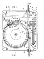
- 10 denotes a cable pulling device which works with a continuous cable 11, which is preferably a wire cable, on the load strand 12 of which the load to be lifted or lowered is suspended, while the lost strand 13 of the cable 11 is load-free.
- the housing 14 of the cable pulling device 10 can be suspended at a fixed point, in which case the load hanging on the load strand 12 is then pulled or relaxed with the load strand.
- the load strand 12 can also be fixed at a fixed point, while the housing 14 of the cable pulling device has a work hanging on the cable stage is firmly connected, which represents the load and with which the cable pulling device moves up and down on the cable.
- cable pulling devices of the type according to the invention are preferably used, the lostrum 13 running out of the cable pulling device generally hanging down freely, but can also be weighted down at the lower end.
- a traction sheave 15 with ball bearings 16 is rotatably mounted in the housing 14, around which the cable 11 rotates.
- the traction sheave 15 has an internal toothing 17, in which a pinion 18 engages, which is driven in rotation by a traction sheave drive, not shown here.
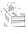
- the traction sheave 15 has an asymmetrical, wedge-shaped cable groove 19, which is shown larger in FIG. 7.
- the traction sheave 15 is provided with a running surface 21 on its outer circumference 20, which is approximately perpendicular to the traction sheave plane 22 and whose purpose will be explained further below.
- flank 23 of the cable groove 19 adjacent to the tread 21 has a greater inclination to the traction sheave plane 22 than the flank 24 facing away from the tread 21.
- This flank 24 facing away can run parallel to the traction sheave plane 22.
- Their angle of inclination a to the traction sheave plane 22 is smaller than the angle of inclination of the opposite flank 23.
- the edge 25 between the tread 21 and the cable groove flank 23 adjacent to it is provided with a greater rounding and the cable groove base 26 is rounded.
- the outer circumference of the traction sheave 15 has a circumferential shoulder 27 into which a circumferential seal 28 accommodated in the housing 14 engages, with which the traction sheave 15 is sealed against the gear oil in which the drive gear of the traction sheave 15 runs .
- the cable 11 is pressed at the end of its looping path by a first pressure roller 29 and a second pressure roller 30 into the cable groove 19 of the traction sheave 15.
- the pressure rollers 29 and 30 are freely rotatably mounted directly one behind the other on a roller carrier 31, which in turn is tiltably mounted on a spring-loaded lever 32.
- the lever 32 is pivotally mounted at its one end 32a on the left in FIG. 1 in the housing 14 and articulated at its other end 32b on the right in FIG. 1 to a pull rod 33 which penetrates a stop plate 34 fastened to the housing 14 and on it lower, free end 34a carries an abutment plate 35.
- the pull rod 33 is surrounded by a strong compression spring 36, which is supported on the one hand on the abutment plate 35 and on the other hand on the underside of the stop plate 34 and the pretensioning thereof can be adjusted by adjusting the abutment plate 35.
- each pressure roller 29 has a narrow radial projection 38 in the central region of its circumferential surface 37, the width and lateral boundary surfaces of which are adapted to the shape of the cable groove 19, so that this radial projection can enter the cable groove. Furthermore, each pressure roller 29 or 30 has radially recessed shoulders 39 laterally next to the radial projection 38, with which the pressure rollers 29 and 30 can be supported on the outer circumference 20 of the traction sheave 15 or on the tread 21 when their radial projection 38 is completely in the cable groove 19 of the traction sheave 15 is immersed.
- the lever 32 which consists of two parts 32 'and 32 ", which enclose the roller carrier 31 between them, is supported with its right end 32b on the stop plate 34 when there is no rope in the cable pulling device. Dive in this position the pressure rollers 29 and 30 with their radial projections 38 into the cable groove 19, but have so much play with their shoulders 39 to the tread 21 of the traction sheave 15 that the roller carrier 31 can carry out small tilting movements about its tilt axis 40. If the roller carrier 31 moves the in Fig.
- the tip of the wire rope used with the rope pulling device according to the invention is somewhat thinner than the control diameter of the rope.
- the cable 11 When the cable 11 is pushed in in the direction of the arrow 42, the cable runs around the traction sheave 15, which in this case rotates in the direction of the arrow 43.
- the rope tip 41 then comes under the first pressure roller 29 and lifts it up a little while it runs onto the rope which has been pushed further and which becomes thicker up to its normal cross section.
- the roller carrier 31 pivots on the one hand about the axis of rotation of the second pressure roller 30 and on the other hand about the tilt axis 40 in FIG. 1 in a clockwise direction, the tilt axis 40 pivoting the lever 32 counterclockwise about its pivot axis 44 and counter to the action of the spring 36 by one small amount stands out from the stop 34.
- the cable tip 41 passes under the peripheral surface 37 of the radial projection 38 of the second pressure roller 30.
- the peripheral surface 37 of this second pressure roller 30 is now at a distance from the bottom of the cable groove that is less than the thickness d of the rope tip 41, but nevertheless the second pressure roller 30 willingly climbs onto the rope tip 41 and then onto the subsequent rope with a regular cross-section, since the first pressure roller 29, which is now already loaded by the spring 36 via the lever 32, one Applies contact pressure to the rope and presses it so firmly into the rope groove 19 that the rope tip 41 is pushed under the second pressure roller 30 with considerable circumferential force.
- inlet pipe 45 for the load strand 12 and in the lower part of the housing 14 an outlet pipe 46 for the lost drum 13 is arranged.
- the two tubes 45 and 46 are fastened with sleeves 47 in the upper and lower housing walls 48 and 49 and adjoin a guide device in tangential planes 50 and 51, which are parallel to each other, which guide means in the circumferential direction of the traction sheave 15 behind the pressure rollers 29 and 30 arranged and is designated in its entirety with 52.
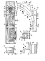
- the guide device 52 is shown in more detail in FIGS. 3 to 6 and consists of a central casting 53 and two cover plates 54 and 55 covering this front and rear.
- the guide device 52 extends approximately over one Quarter circle, covers the cable groove 19 and the tread 21 of the traction sheave 15 on the circumferential and lateral sides and is fastened in the housing 14 in such a way that its vertical leg 52a lies in the tangential planes 50 and 51, in which the load strand 12 enters or the lost strand 13 des Rope runs out of the cable pulling device 10.
- the inlet guide 56 in the form of an inlet channel for the load strand, which is arranged tangentially to the cable groove 19, adjoins the inlet tube 45 and whose axis 57 lies in the tangential plane 50 in which the load strand 12 rests the rope groove 19 of the traction sheave 15 runs up.
- the inlet channel 56 opens into a first guide channel 58 which is open towards the cable groove 19, the lateral boundary of which forms a first guide surface 58a and which is covered on its rear side by the rear cover plate 55 and towards the front into a second guide channel 59 for the lost drum 13 of the rope, to which the outlet pipe 46 connects.
- the second guide channel 59 for the lost drum is offset from the first guide channel 58 for the incoming load strand 12, so it is located in a plane lying in front of the cable groove 19, in which the running surface 21 of the traction sheave 15 is also located.
- this guide channel 59 the lost drum 13 lifted out of the cable groove 19 behind the pressure roller 30 is guided via a lateral ramp 60 which is formed in the casting 53 and which guides the cable lifted out of the cable groove 19 sideways onto the running surface 21 of the drive pulley 15.
- the casting 53 has a tongue 61, the tongue tip 62 of which extends to the bottom of the cable groove 26 of the traction sheave 15 and which forms a radial ramp 63 rising in the circumferential direction 43 of the traction sheave 15.
- the rope tip 41 and subsequently the rope 11 rotating around the traction sheave 15 is lifted from the tip of the tongue 62, runs outwards via the radial ramp 63 and is then guided via the lateral ramp 60 onto the running surface 21 of the traction sheave, the rope at the back through a curved second guide surface 64 is guided from the tongue 61 through the guide channel 59 into the drain pipe 46.
- a circumferential cover 65 for the traction sheave 15 adjoins the first guide surface 58a of the inlet channel 58 in the casting 53, which extends as far as the pressure rollers 29 and 30 and the cable 11 lying in the cable groove 19 on its back covers.
- the spring-loaded lever could also be a rocker arm, on one end of which the roller carrier is mounted and on the other end of which the spring engages.
- a projection on the housing could also be provided as a stop for the lever.
- the V-groove can also be designed differently; but it is essential that the wedge angle is kept relatively small, so that low pressure forces are sufficient to press the rope into the groove and still be able to transmit a sufficiently high tensile force.
Landscapes
- Engineering & Computer Science (AREA)
- Mechanical Engineering (AREA)
- Pulleys (AREA)
- Electric Cable Installation (AREA)
- Forwarding And Storing Of Filamentary Material (AREA)
- Guides For Winding Or Rewinding, Or Guides For Filamentary Materials (AREA)
- Lift-Guide Devices, And Elevator Ropes And Cables (AREA)
Applications Claiming Priority (2)
| Application Number | Priority Date | Filing Date | Title |
|---|---|---|---|
| DE3509920 | 1985-03-19 | ||
| DE3509920A DE3509920C2 (de) | 1985-03-19 | 1985-03-19 | Seilzugvorrichtung |
Publications (2)
| Publication Number | Publication Date |
|---|---|
| EP0197877A1 true EP0197877A1 (fr) | 1986-10-15 |
| EP0197877B1 EP0197877B1 (fr) | 1988-09-21 |
Family
ID=6265708
Family Applications (1)
| Application Number | Title | Priority Date | Filing Date |
|---|---|---|---|
| EP86630033A Expired EP0197877B1 (fr) | 1985-03-19 | 1986-03-06 | Appareil de traction de câble |
Country Status (11)
| Country | Link |
|---|---|
| US (1) | US4706940A (fr) |
| EP (1) | EP0197877B1 (fr) |
| JP (1) | JPS61217497A (fr) |
| CN (1) | CN1004415B (fr) |
| AU (1) | AU584994B2 (fr) |
| BR (1) | BR8601172A (fr) |
| CA (1) | CA1249580A (fr) |
| CS (1) | CS262431B2 (fr) |
| DE (1) | DE3509920C2 (fr) |
| ES (1) | ES8702295A1 (fr) |
| ZA (1) | ZA861854B (fr) |
Cited By (4)
| Publication number | Priority date | Publication date | Assignee | Title |
|---|---|---|---|---|
| EP0360033A1 (fr) * | 1988-09-23 | 1990-03-28 | Greifzug Hebezeugbau Gmbh | Appareil de traction à câble |
| FR2638802A2 (fr) * | 1988-06-03 | 1990-05-11 | Secalt | Appareil pour l'entrainement d'un lien souple tel qu'une sangle ou une courroie |
| FR2646661A1 (fr) * | 1989-05-05 | 1990-11-09 | Maxwell Marine Ltd | Treuil pour manipulation d'ancre |
| WO1996012667A1 (fr) * | 1994-10-21 | 1996-05-02 | Gerhard Rumpp | Treuil de man×uvre |
Families Citing this family (29)
| Publication number | Priority date | Publication date | Assignee | Title |
|---|---|---|---|---|
| USD298979S (en) | 1986-06-30 | 1988-12-13 | Row Scott W | Ceiling winch |
| GB8627684D0 (en) * | 1986-11-19 | 1986-12-17 | Bellway Plc | Vehicle winch |
| USD388928S (en) | 1995-03-30 | 1998-01-06 | Nihon Biso Co., Ltd. | Traction hoist used in a powered suspended scaffold |
| US5669575A (en) * | 1995-11-29 | 1997-09-23 | The United States Of America As Represented By The Secretary Of The Navy | Apparatus for controlling a cable on a take-up drum |
| USD388929S (en) | 1996-12-04 | 1998-01-06 | Nihon Biso Co., Ltd. | Traction hoist used in a powered suspended scaffold |
| US6098962A (en) * | 1997-03-04 | 2000-08-08 | Lewmar Mrine Limited | Winch |
| US6237502B1 (en) * | 1998-07-14 | 2001-05-29 | Richard Van Damme | Sheave arrangement suitable for slack pulling carriage |
| DE19911073C2 (de) * | 1999-03-12 | 2003-04-30 | Rotzler Gmbh Co | Seilfenster für Seilwinden |
| US6708954B2 (en) * | 2000-06-16 | 2004-03-23 | Maxwell Marine Limited | Winch |
| USD490203S1 (en) | 2002-10-04 | 2004-05-18 | Teijin Seiki Co., Ltd. | Hoist for an elevator |
| DE102004010308B4 (de) * | 2004-03-03 | 2006-07-27 | Greifzug Hebezeugbau Gmbh | Treibscheibenhubwerk für Bühne und Befahranlage hiermit |
| USD534704S1 (en) * | 2004-03-30 | 2007-01-02 | Doyle's Deer Gear | Object lifting device |
| US8317160B2 (en) * | 2007-10-12 | 2012-11-27 | Safeworks, Llc | Restraint device for traction sheaves |
| SG154361A1 (en) * | 2008-01-30 | 2009-08-28 | Seow Tiong Bin | A hoist |
| US8517345B2 (en) * | 2010-08-03 | 2013-08-27 | United States Of America, As Represented By The Secretary Of The Navy | Shipboard winch with guide vanes |
| ES1073935Y (es) * | 2010-10-21 | 2011-06-09 | Elevadores Goian S L | Aparato elevador por cable |
| FR2973021B1 (fr) * | 2011-03-23 | 2013-04-05 | Fixator | Treuil a adherence pour la manutention de charges |
| USD734588S1 (en) | 2012-09-05 | 2015-07-14 | Tractel Greifzug Gmbh | Lifting apparatus |
| CN103272812A (zh) * | 2013-05-06 | 2013-09-04 | 广西壮族自治区机械工业研究院 | 列管式加热器全自动清洗设备防高压水枪软管打卷装置 |
| CN103212559A (zh) * | 2013-05-06 | 2013-07-24 | 广西壮族自治区机械工业研究院 | 列管式加热器全自动清洗设备的高压水枪轮式输送机构 |
| CN103240253A (zh) * | 2013-05-06 | 2013-08-14 | 广西壮族自治区机械工业研究院 | 列管式加热器全自动清洗设备的高压水枪轮式输送机构 |
| LU92298B1 (fr) * | 2013-10-28 | 2015-04-29 | Capital Access Sarl | Treuil à poulie d'adhérence autonome |
| JP6713262B2 (ja) * | 2015-10-14 | 2020-06-24 | シャープ株式会社 | 駆動装置、画像読取装置および画像形成装置 |
| CN105329701B (zh) * | 2015-10-14 | 2018-07-13 | 苏州惠斯福自动化科技有限公司 | 自动送线器的送线控制装置 |
| DE102017101656A1 (de) | 2017-01-27 | 2018-08-02 | Technische Universität Dresden | Seildurchlaufwinde |
| CN109335980B (zh) * | 2018-09-29 | 2020-03-31 | 中铁十六局集团铁运工程有限公司 | 一种高边坡石料运输装置及方法 |
| CN111732014A (zh) * | 2020-07-22 | 2020-10-02 | 吉林大学青岛汽车研究院 | 一种位置可调的绳索导向张紧机构 |
| CN114803912B (zh) * | 2022-06-13 | 2025-12-16 | 牛建华 | 一种吊篮提升机 |
| US12297086B2 (en) * | 2022-11-21 | 2025-05-13 | Hornet Acquisitionco, Llc | Cable follower lifting lever |
Citations (9)
| Publication number | Priority date | Publication date | Assignee | Title |
|---|---|---|---|---|
| GB197317A (en) * | 1922-05-03 | 1923-10-25 | Simon Faure | Improvements relating to hand operated lifting apparatus |
| DE1246202B (de) * | 1964-08-13 | 1967-08-03 | Wilhelm Luedecke | Spill |
| US3608389A (en) * | 1969-12-05 | 1971-09-28 | George C Christian | Load responsive gripping device for flexible cable drives and the like |
| BE827486A (nl) * | 1975-04-03 | 1975-07-31 | Verbeterde lier | |
| US3944185A (en) * | 1974-06-28 | 1976-03-16 | Mayco Equipment Co., Inc. | Hoist apparatus |
| DE2522033A1 (de) * | 1975-05-17 | 1976-11-25 | Greifzug Hebezeugbau Gmbh | Treibscheibentriebwerk |
| GB2002711A (en) * | 1977-08-17 | 1979-02-28 | Nippon Biso Kk | Rope traction apparatus |
| FR2539730A1 (fr) * | 1983-01-20 | 1984-07-27 | Chiers Chatillon Gorcy Trefil | Treuil a adherence |
| GB2142602A (en) * | 1983-06-23 | 1985-01-23 | Power Climber Inc | A hoist and transmission, traction and brake systems for use therewith |
Family Cites Families (5)
| Publication number | Priority date | Publication date | Assignee | Title |
|---|---|---|---|---|
| US2907534A (en) * | 1955-03-08 | 1959-10-06 | Stewart Warner Corp | Hose reel |
| GB1068251A (en) * | 1963-02-22 | 1967-05-10 | James N Miller & Sons Ltd | Improvements in or relating to fishing line haulage gear |
| US3729173A (en) * | 1972-01-24 | 1973-04-24 | Tractel Sa | Endless jaw chain self-clamping winch |
| US4005852A (en) * | 1975-06-27 | 1977-02-01 | The United States Of America As Represented By The Secretary Of The Air Force | Traction sheave warning for helicopter rescue hoist systems |
| US4225118A (en) * | 1978-11-20 | 1980-09-30 | Barient Company | Direct drive deck winch |
-
1985
- 1985-03-19 DE DE3509920A patent/DE3509920C2/de not_active Expired - Lifetime
-
1986
- 1986-03-06 EP EP86630033A patent/EP0197877B1/fr not_active Expired
- 1986-03-07 JP JP61050244A patent/JPS61217497A/ja active Pending
- 1986-03-12 ZA ZA861854A patent/ZA861854B/xx unknown
- 1986-03-13 CA CA000504055A patent/CA1249580A/fr not_active Expired
- 1986-03-14 AU AU54846/86A patent/AU584994B2/en not_active Ceased
- 1986-03-14 US US06/839,726 patent/US4706940A/en not_active Expired - Lifetime
- 1986-03-17 CS CS861872A patent/CS262431B2/cs unknown
- 1986-03-17 BR BR8601172A patent/BR8601172A/pt not_active IP Right Cessation
- 1986-03-18 CN CN86101741.2A patent/CN1004415B/zh not_active Expired
- 1986-03-18 ES ES553097A patent/ES8702295A1/es not_active Expired
Patent Citations (9)
| Publication number | Priority date | Publication date | Assignee | Title |
|---|---|---|---|---|
| GB197317A (en) * | 1922-05-03 | 1923-10-25 | Simon Faure | Improvements relating to hand operated lifting apparatus |
| DE1246202B (de) * | 1964-08-13 | 1967-08-03 | Wilhelm Luedecke | Spill |
| US3608389A (en) * | 1969-12-05 | 1971-09-28 | George C Christian | Load responsive gripping device for flexible cable drives and the like |
| US3944185A (en) * | 1974-06-28 | 1976-03-16 | Mayco Equipment Co., Inc. | Hoist apparatus |
| BE827486A (nl) * | 1975-04-03 | 1975-07-31 | Verbeterde lier | |
| DE2522033A1 (de) * | 1975-05-17 | 1976-11-25 | Greifzug Hebezeugbau Gmbh | Treibscheibentriebwerk |
| GB2002711A (en) * | 1977-08-17 | 1979-02-28 | Nippon Biso Kk | Rope traction apparatus |
| FR2539730A1 (fr) * | 1983-01-20 | 1984-07-27 | Chiers Chatillon Gorcy Trefil | Treuil a adherence |
| GB2142602A (en) * | 1983-06-23 | 1985-01-23 | Power Climber Inc | A hoist and transmission, traction and brake systems for use therewith |
Cited By (4)
| Publication number | Priority date | Publication date | Assignee | Title |
|---|---|---|---|---|
| FR2638802A2 (fr) * | 1988-06-03 | 1990-05-11 | Secalt | Appareil pour l'entrainement d'un lien souple tel qu'une sangle ou une courroie |
| EP0360033A1 (fr) * | 1988-09-23 | 1990-03-28 | Greifzug Hebezeugbau Gmbh | Appareil de traction à câble |
| FR2646661A1 (fr) * | 1989-05-05 | 1990-11-09 | Maxwell Marine Ltd | Treuil pour manipulation d'ancre |
| WO1996012667A1 (fr) * | 1994-10-21 | 1996-05-02 | Gerhard Rumpp | Treuil de man×uvre |
Also Published As
| Publication number | Publication date |
|---|---|
| CS262431B2 (en) | 1989-03-14 |
| ZA861854B (en) | 1986-10-29 |
| BR8601172A (pt) | 1986-11-25 |
| ES553097A0 (es) | 1987-01-01 |
| CN86101741A (zh) | 1986-09-24 |
| CA1249580A (fr) | 1989-01-31 |
| CN1004415B (zh) | 1989-06-07 |
| DE3509920A1 (de) | 1986-09-25 |
| AU5484686A (en) | 1986-09-25 |
| AU584994B2 (en) | 1989-06-08 |
| JPS61217497A (ja) | 1986-09-27 |
| DE3509920C2 (de) | 1993-11-25 |
| ES8702295A1 (es) | 1987-01-01 |
| EP0197877B1 (fr) | 1988-09-21 |
| US4706940A (en) | 1987-11-17 |
| CS187286A2 (en) | 1988-07-15 |
Similar Documents
| Publication | Publication Date | Title |
|---|---|---|
| EP0197877B1 (fr) | Appareil de traction de câble | |
| DE2522033C2 (de) | Treibscheibentriebwerk | |
| DE69203085T3 (de) | Antriebsvorrichtung für eine Ziehmaschine. | |
| EP3337749B1 (fr) | Poullie a courroie pour ascenseur | |
| DE69512294T2 (de) | Vorrichtung zum Einbringen eines Dränagebandes | |
| DE3832360C1 (fr) | ||
| DE2144330A1 (de) | Hebevorrichtung | |
| DE2937293C2 (de) | Seilandruckvorrichtung für Seilscheiben | |
| DE3042254C2 (de) | Umschnürungsvorrichtung an landwirtschaftlichen Rollballenpressen | |
| DE19947806B4 (de) | Kettenziehmaschine zum kontinuierlichen Ziehen von Ziehgut | |
| DE3407729A1 (de) | Zufuehrvorrichtung fuer die fuehrung des seils auf der seiltrommel einer winde | |
| DE3834399C2 (fr) | ||
| DE102006056244A1 (de) | Vorrichtung zum Auf- und Abwickeln von strangartigem Wickelgut | |
| DE2263521C2 (de) | Seilführungsvorrichtung an Windentrommeln | |
| DE69301679T2 (de) | Förderer | |
| DE68902870T2 (de) | Winde zum antreiben eines bandes. | |
| DE2201548C3 (de) | Seilwinde für unbegrenzten Seildurchlauf | |
| DE19942608A1 (de) | Seilwinde, insbesondere mit einer Antriebskurbel versehene Handwinde | |
| DE10328487B4 (de) | Hubvorrichtung | |
| DE3202464C2 (de) | Ankerpfahlbetätigung | |
| DE19510350A1 (de) | Einseil-Treibscheibenwinde | |
| DE3818409A1 (de) | Zugwalze | |
| EP0518853A1 (fr) | Dispositif pour l'enroulement de câbles sur un tambour | |
| DE3229801C2 (de) | Seilbremse zum selbsttätigen Abbremsen eines Seiles | |
| DE3017969A1 (de) | Spanneinrichtung fuer einen senkrechtfoerderer, insbesondere ein becherwerk |
Legal Events
| Date | Code | Title | Description |
|---|---|---|---|
| PUAI | Public reference made under article 153(3) epc to a published international application that has entered the european phase |
Free format text: ORIGINAL CODE: 0009012 |
|
| AK | Designated contracting states |
Kind code of ref document: A1 Designated state(s): BE CH FR GB IT LI LU NL |
|
| 17P | Request for examination filed |
Effective date: 19870402 |
|
| 17Q | First examination report despatched |
Effective date: 19871208 |
|
| GRAA | (expected) grant |
Free format text: ORIGINAL CODE: 0009210 |
|
| AK | Designated contracting states |
Kind code of ref document: B1 Designated state(s): BE CH FR GB IT LI LU NL |
|
| ET | Fr: translation filed | ||
| GBT | Gb: translation of ep patent filed (gb section 77(6)(a)/1977) | ||
| ITF | It: translation for a ep patent filed | ||
| PLBE | No opposition filed within time limit |
Free format text: ORIGINAL CODE: 0009261 |
|
| STAA | Information on the status of an ep patent application or granted ep patent |
Free format text: STATUS: NO OPPOSITION FILED WITHIN TIME LIMIT |
|
| 26N | No opposition filed | ||
| ITTA | It: last paid annual fee | ||
| EPTA | Lu: last paid annual fee | ||
| PGFP | Annual fee paid to national office [announced via postgrant information from national office to epo] |
Ref country code: LU Payment date: 19950201 Year of fee payment: 10 |
|
| PGFP | Annual fee paid to national office [announced via postgrant information from national office to epo] |
Ref country code: CH Payment date: 19950213 Year of fee payment: 10 |
|
| PGFP | Annual fee paid to national office [announced via postgrant information from national office to epo] |
Ref country code: NL Payment date: 19950331 Year of fee payment: 10 |
|
| PG25 | Lapsed in a contracting state [announced via postgrant information from national office to epo] |
Ref country code: LU Free format text: LAPSE BECAUSE OF NON-PAYMENT OF DUE FEES Effective date: 19960306 |
|
| PG25 | Lapsed in a contracting state [announced via postgrant information from national office to epo] |
Ref country code: LI Effective date: 19960331 Ref country code: CH Effective date: 19960331 |
|
| PG25 | Lapsed in a contracting state [announced via postgrant information from national office to epo] |
Ref country code: NL Effective date: 19961001 |
|
| REG | Reference to a national code |
Ref country code: CH Ref legal event code: PL |
|
| NLV4 | Nl: lapsed or anulled due to non-payment of the annual fee |
Effective date: 19961001 |
|
| REG | Reference to a national code |
Ref country code: GB Ref legal event code: IF02 |
|
| PGFP | Annual fee paid to national office [announced via postgrant information from national office to epo] |
Ref country code: GB Payment date: 20050221 Year of fee payment: 20 |
|
| PG25 | Lapsed in a contracting state [announced via postgrant information from national office to epo] |
Ref country code: IT Free format text: LAPSE BECAUSE OF NON-PAYMENT OF DUE FEES;WARNING: LAPSES OF ITALIAN PATENTS WITH EFFECTIVE DATE BEFORE 2007 MAY HAVE OCCURRED AT ANY TIME BEFORE 2007. THE CORRECT EFFECTIVE DATE MAY BE DIFFERENT FROM THE ONE RECORDED. Effective date: 20050306 |
|
| PGFP | Annual fee paid to national office [announced via postgrant information from national office to epo] |
Ref country code: FR Payment date: 20050311 Year of fee payment: 20 |
|
| PGFP | Annual fee paid to national office [announced via postgrant information from national office to epo] |
Ref country code: BE Payment date: 20050422 Year of fee payment: 20 |
|
| PG25 | Lapsed in a contracting state [announced via postgrant information from national office to epo] |
Ref country code: GB Free format text: LAPSE BECAUSE OF EXPIRATION OF PROTECTION Effective date: 20060305 |
|
| REG | Reference to a national code |
Ref country code: GB Ref legal event code: PE20 |
|
| BE20 | Be: patent expired |
Owner name: *GREIFZUG HEBEZEUGBAU G.M.B.H. Effective date: 20060306 |