EP0198166A2 - Dispositif de correction pneumatique à membrane pour une pompe d'injection de combustible des moteurs à combustion interne - Google Patents
Dispositif de correction pneumatique à membrane pour une pompe d'injection de combustible des moteurs à combustion interne Download PDFInfo
- Publication number
- EP0198166A2 EP0198166A2 EP86101703A EP86101703A EP0198166A2 EP 0198166 A2 EP0198166 A2 EP 0198166A2 EP 86101703 A EP86101703 A EP 86101703A EP 86101703 A EP86101703 A EP 86101703A EP 0198166 A2 EP0198166 A2 EP 0198166A2
- Authority
- EP
- European Patent Office
- Prior art keywords
- push rod
- stop
- spring
- displacement path
- end stop
- Prior art date
- Legal status (The legal status is an assumption and is not a legal conclusion. Google has not performed a legal analysis and makes no representation as to the accuracy of the status listed.)
- Granted
Links
Images

Classifications
-
- F—MECHANICAL ENGINEERING; LIGHTING; HEATING; WEAPONS; BLASTING
- F02—COMBUSTION ENGINES; HOT-GAS OR COMBUSTION-PRODUCT ENGINE PLANTS
- F02D—CONTROLLING COMBUSTION ENGINES
- F02D1/00—Controlling fuel-injection pumps, e.g. of high pressure injection type
- F02D1/02—Controlling fuel-injection pumps, e.g. of high pressure injection type not restricted to adjustment of injection timing, e.g. varying amount of fuel delivered
- F02D1/06—Controlling fuel-injection pumps, e.g. of high pressure injection type not restricted to adjustment of injection timing, e.g. varying amount of fuel delivered by means dependent on pressure of engine working fluid
- F02D1/065—Controlling fuel-injection pumps, e.g. of high pressure injection type not restricted to adjustment of injection timing, e.g. varying amount of fuel delivered by means dependent on pressure of engine working fluid of intake of air
-
- F—MECHANICAL ENGINEERING; LIGHTING; HEATING; WEAPONS; BLASTING
- F02—COMBUSTION ENGINES; HOT-GAS OR COMBUSTION-PRODUCT ENGINE PLANTS
- F02B—INTERNAL-COMBUSTION PISTON ENGINES; COMBUSTION ENGINES IN GENERAL
- F02B3/00—Engines characterised by air compression and subsequent fuel addition
- F02B3/06—Engines characterised by air compression and subsequent fuel addition with compression ignition
Definitions
- the invention relates to a pneumatic membrane actuator for a fuel injection device of internal combustion engines, in particular of supercharged diesel engines.
- Such a pneumatic diaphragm actuator realizes a boost pressure-dependent full load stop (LDA) in so-called supercharging engines.
- LDA boost pressure-dependent full load stop
- This LDA is used to reduce the amount of fuel delivered at full load in the lower speed range from a certain boost pressure.
- the diaphragm actuator can be attached to the fuel injection pump of the fuel injection device and can act on a delivery rate adjustment element via a control element or on a centrifugal force rotation Number controller of the fuel injection device be flanged and act on a control lever on a control lever, which in turn controls the flow rate adjustment.
- the counterstop is designed as an adjusting nut which can be screwed onto an external thread section of the push rod and which is connected to a counter nut after setting the max. permissible displacement of the push rod is fixed on the push rod.
- the suction quantity due to the length of the stop screw protruding into the pressure chamber is determined by the relative position of the adjusting nut on the push rod and the pressure range by the preload of the return spring that can be adjusted by means of an abutment.
- the known diaphragm member has only a linear control characteristic within the effective pressure range, i.e. a linear dependency of the adjustment path of the push rod on the boost pressure prevailing in the pressure chamber, which often does not meet the requirements for influencing or controlling the fuel delivery quantity.
- the pneumatic diaphragm actuator according to the invention with the characterizing features of claim 1 has the advantage, in contrast, of achieving an improved coordination of the control path required for fuel quantity control, for example depending on the boost pressure.
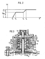
- the preloaded spring assembly with the two stop positions enables a control characteristic curve, in which - as before - after reaching a minimum boost pressure in the pressure chamber, an adjustment movement of the push rod that is proportional to the boost pressure increase begins.
- the first stop position of the spring assembly When the first stop position of the spring assembly is reached, its spring pretensioning force becomes effective, so that the boost pressure has to rise to a second, higher minimum pressure until a further adjustment movement of the push rod, which is again proportional to the pressure increase, begins.
- Both the position of the push rod in the first and in the second in contrast higher minimum pressure and the total path of the push rod displacement can be set very easily separately from one another and without mutual interference. B, a constant torque can be controlled on the internal combustion engine over a large speed range.
- Steepness can also be changed in the first linear adjustment range and thus an improved adjustment solution to the required conditions.
- the spring assembly is screwed into an internal thread in the wall of the pressure chamber and, with its installation position, defines the further displacement path of the push rod.
- This embodiment variant is particularly advantageous when the mass attached to the push rod should be as small as possible due to low actuating forces, in order to exclude undesired actuating movements due to the acceleration forces occurring on the diesel engine.
- this spring assembly can either be installed as a preset spring capsule for easy assembly and readjustment, or it can be used for a fully adjustable boost pressure stop. In this case, both the displacement of the push rod for the two adjustment stages and the pretensioning forces of the return spring and the compression spring can then be adjusted and adjusted independently of one another and, with the correct setting sequence, independently of one another.
- the pneumatic diaphragm actuator shown in FIG. 1 as the preferred first exemplary embodiment and suitable for attachment to a fuel injection pump or a centrifugal speed governor of a fuel injection device is an actuator of a boost-pressure-dependent full-load stop and has a two-part housing 10 with a first and second housing part 11, 12, which are screwed together by clamping a membrane 13.
- the end of the second housing part 12 is covered with a housing cover J4, which closes together with the membrane 13 delimits a pressure chamber 15 in the second housing part 12, to which the charge air pressure prevailing in the intake line of the engine is supplied via a connection bore 16.
- a push rod 17 is axially displaceably guided in a bearing sleeve 18, which is screwed into the bottom of the first housing part 11 and forms an adjustable abutment for a return spring 19 which coaxially surrounds the push rod 17 and which is formed on the membrane 13 with the interposition of a connecting plate 20 supports.
- the push rod 17 cooperates with its end protruding from the housing 10 via a hinged control member 21 with a control rod, not shown, in the fuel injection device.
- the push rod 17 projects with a reduced-diameter push rod section 17a through the membrane 13 into the pressure chamber 15 in the second housing part 12 and is connected to the membrane 13 by the fact that on the side of the membrane 13 opposite the connecting plate 20, a further connecting plate 22 the push rod section 17a is pushed on and is pressed against a ring shoulder 25 on the push rod section 17b having the larger diameter by a clamping nut 24 which can be screwed onto an external thread 23 of the push rod section 17a.
- the push rod 17 is axially displaceable by means of the membrane 13 when the pressure chamber 15 is pressurized against the force of the return spring 19 between two end stops 26, 27 fixed to the housing. Both end stops 26, 27 are arranged in the pressure chamber 15.
- the first end stop 26 is formed by a stop screw 28 which in Ge Housing cover 14 can be screwed and is aligned with the push rod 17. In the selected stop position, the stop screw 28 is fixed on the housing cover 14 by means of a lock nut 29.
- the end face of the push rod section 17a lies against this stop screw 28 in the drawn, unpressurized starting position of the push rod 17.
- the stop screw 28 serves to determine the starting position of the push rod 17 when the pressure chamber 15 is depressurized and thus to determine the suction quantity.
- the second end stop 27 is arranged on an annular radial web 30 projecting axially from the housing cover 14 into the interior of the pressure chamber 15, in the form of an annular disk 31 made of hardened spring steel.
- the housing-fixed annular disc 31 interacts with a counter stop 32 which is adjustably fastened on the push rod 17, specifically on the push rod section 17a.
- the counter attack. 32 determines the position of the push rod 17 at full charge pressure and thus defines the full load quantity at full charge pressure, the so-called loader quantity.
- the counter stop 32 is designed as part of a prestressed spring assembly 33 with two stop positions such that when the first stop position is reached on the annular disk 31 after the push rod displacement path S has been covered . after overcoming the spring preload of the spring assembly 33, a further displacement path S 2 of the push rod 17 is available until the second stop position on the annular disc 31 is reached. In the further displacement S 2 , the spring force of the spring assembly 33 and the spring force of the return spring 19 add up.
- the spring assembly 33 has a cylindrical guide part 34 with an axial stepped bore 35.
- the bore section 35a with the smaller diameter carries an internal thread 36 with which the guide part 34 is screwed onto the external thread 23 of the push rod section 17a.
- the guide part 34 is countered by a locking nut 38 which can be screwed inside the larger diameter bore section 35b onto the external thread 23 of the push rod section 17a, the locking nut 38 pressing against the transition shoulder 35c located between the bore sections 35a and 35b.
- the guide part 34 On the end face facing the ring disk 31, the guide part 34 carries a radially outwardly projecting ring flange 39, the ring surface of which faces away from the ring disk 31 forms a driving shoulder 40 for a spring support part 41, which is held axially displaceably on an outer guide surface 42 of the guide part 34.
- the hollow cylindrical spring support member 41 rests with its inner cylinder wall on the outer guide surface 42 of the guide member 34 and has a concentric recess 43 in its end face facing the annular disk 31, the diameter of which is larger than the outer diameter of the annular flange 39 of the guide member 34.
- the depth of the recess 43 is dimensioned larger than the sum of the axial thickness of the ring flange 39 and the desired displacement S 2 of the guide part 34 or the push rod 17 after reaching the first stop position of the spring assembly 33.
- a spacer 45 is inserted between the driving shoulder 40 on the ring flange 39 and a bottom ring surface 44 of the recess 43 for the exact adjustment of the displacement path 5 2 .
- the spring support part 41 is pressed by a compression spring 46 coaxially surrounding the spring support part 41 and the guide part 34 with the base ring surface 44 of the recess 43 against the spacer 45 and this against the driving shoulder 40 of the ring flange 39 on the guide part 34.
- the compression spring 46 is supported on an annular support shoulder 47 on the spring support part 41 and on an adjusting ring 48 which can be screwed onto an externally threaded section 49 of the guide part 34.
- the prestress of the compression spring 46 can be adjusted by screwing the adjusting ring 48 more or less far onto the guide part 34.
- the end face configuration of the spring support part 41 is such that the end face remaining ring surface and the outside diameter of the spring support part 41 correspond to the ring width and outside diameter of the washer 31, which is arranged concentrically with the push rod 1-7 and forms the second end stop 27.
- the spring assembly 33 is preassembled in such a way that the spring support part 41 is first pushed onto the guide part 34 and the displacement path S 2 is determined by means of the spacer 45. Then the compression spring 46 is placed and the bias of the compression spring 46 is determined by means of the adjusting ring 48. Thereafter, the spring assembly pre-assembled and pre-set is so far screwed 33 with the guide member 34 onto the external thread 23 of the push rod portion 17a, that the displacement - is Beweg set S 1, and locked by the locking nut 38th
- the basic position of the push rod 17 is set with the stop screw 28 when the pressure chamber 15 is depressurized.
- this position of the stop screw 28 is fixed.
- Setting the bias of the return spring 19 is set.
- the prestress of the compression spring 46 in the spring assembly 33 is corrected by turning the adjusting ring 48 such that the renewed start of the adjustment of the push rod 17 after passing through the first displacement path S 1 starts when the desired second minimum boost pressure p 3 is reached .
- the invention is not restricted to the first exemplary embodiment described above.
- the two mutually braced coaxial components of the spring assembly 33 which in the first exemplary embodiment are formed by the guide part 34 and the spring support part 41, do not have to sit on the push rod, but rather are coaxial in the second housing part 12 in the second exemplary embodiment described below the push rod 17 held.
- the second exemplary embodiment shown in FIG. 3 differs from the first exemplary embodiment described in relation to FIG. 1, as already indicated in the previous section, essentially by the modified embodiment of the spring assembly 33A.
- the same parts are given the same name, different parts are given the capital letter A and new parts are renamed.
- the spring assembly 33A is screwed into an internal thread 51 in the wall of the pressure chamber J5, forms the counter-stop 32A at the end, has a distance that defines the further displacement path S 2 of the push rod 17 from the second end stop 27, and is secured in this position by a locking screw 52 fixed in the second housing part J2 of the actuator housing 10 and coaxially to the push rod J7.
- One of the two components of the spring construction which are arranged so as to be displaceable relative to one another and braced against one another by means of the compression spring 46 Group 33A is formed by a threaded sleeve 53 with an adjusting sleeve 55 screwed into an internal thread 54 of this sleeve, and the second component is a spring support part 41A arranged axially displaceably between push rod 17 and threaded sleeve 53 with adjusting sleeve 55 and coaxial with these parts.
- the compression spring 46 is supported on the one hand on a support shoulder 56 within the threaded sleeve 53 and on the other hand on an annular flange 58 projecting radially from the spring support part 41A.
- annular flange 58 is pressed in the position shown by the compression spring 46 in contact with an inner shoulder 55a of the adjusting sleeve 55, and the support shoulder 56 is formed by an end face of an annular disc 59 facing the compression spring 46, which in turn is not closer to one in one designated annular groove inserted inner snap ring 60.
- a stop shoulder 61a is formed from a recess 61 open to the first end stop 26 formed by the stop screw 28 within the spring support part 41A, and the push rod 17 carries one on its threaded push rod section 17a in the region between the first end stop 26 and the stop shoulder 61a by a lock nut 62 in the illustrated installation position secured adjusting nut 63.
- the adjusting nut 63 is set such that between the stop shoulder 61a in the spring support part 41A and a stop surface 63a on the adjusting nut 63 there is a distance defining the first displacement path S j .
- the abutment surface 63a is located on a shoulder between a section of reduced diameter, not designated in any more detail, and an annular collar 64 of this adjusting nut 63.
- the annular collar 64 has recesses on its circumference which correspond to the Enabling engagement of an adjusting tool, and the lock nut 62 has corresponding end recesses 62a, so that both nuts 62, 63 can be adjusted and countered by a double-walled tubular tool.
- the threaded sleeve 53 is also provided on the end face with transverse grooves 53a, which are used to engage a tool, and the adjusting sleeve 55 has a hexagon socket 55b or a similarly shaped opening for the engagement of a corresponding tool.
- the setting of the second exemplary embodiment of the diaphragm actuator shown in FIG. 3 deviates in some work steps from that of the first exemplary embodiment according to FIG. 1.
- the setting of the drawn basic position of the push rod 17 when the suction chamber 15 is depressurized by means of the stop screw 28 secured by the lock nut 29 and the setting of the prestressing of the return spring 19 for the initial displacement of the push rod 17 starting at the minimum boost pressure p 1 are carried out in the same way as in the first exemplary embodiment.
- the housing cover 14 is removed, and the spring assembly 41A and the adjusting nut 63 are brought into their drawn position, in which the displacement paths S 1 and S 2 can be controlled.
- the push rod is then moved into a position for the maximum displacement path S max , which is composed of the sum of the two displacement paths S 1 and S 2 .
- the push rod 17 is fixed and the adjusting nut 63 is screwed in until its stop surface 63a abuts the stop shoulder 61a and secured in this position by the lock nut 62.
- the push rod 17 is moved back by the displacement S 2 in the direction of the stop 26 and the threaded sleeve 53 is moved back by the same amount, so that the stop shoulder 61a rests against the stop surface 63a.
- the spring support part 41A is now in the drawn position, which defines the displacement path S 2 . If the spring preload of the compression spring 46 had already been preset by setting the adjusting sleeve 55 before installation, the entire setting has now ended.
- the push rod 17 strikes the first end stop 26 and the stop shoulder 61a then assumes the distance from the stop surface 63a which defines the displacement path S 1 .
- both the displacement paths S j and S 2 and the measuring points for the respective start of adjustment at the charging pressures p 1 and p 3 can be adjusted and adjusted continuously.
- the components clamped together to form the preset spring assembly 33A that is, the threaded sleeve 53 with the adjusting sleeve 55 and the spring support part 41A, on the one hand with the push rod 17 and on the other hand with the second end stop 27 in such an operative connection that after covering the first displacement S 1 against the restoring force of the return spring 19, a first stop position is reached and then after overcoming the biasing force of the compression spring 46 by relative displacement of these components against the spring force of the compression spring 46, the further displacement S 2 of the push rod 17 to the second Stop position at the second end stop 27 is available.
- the push rod restoring force is increased by the spring force of the compression spring 46, and, as in the first exemplary embodiment, the flatter course of the displacement path characteristic curve drawn in FIG. 2 between the charging pressures p 3 and P4 is obtained compared to the steeper one Course between p 1 and p 2 .
Landscapes
- Engineering & Computer Science (AREA)
- Chemical & Material Sciences (AREA)
- Combustion & Propulsion (AREA)
- Mechanical Engineering (AREA)
- General Engineering & Computer Science (AREA)
- High-Pressure Fuel Injection Pump Control (AREA)
- Actuator (AREA)
- Fuel-Injection Apparatus (AREA)
- Reciprocating Pumps (AREA)
Priority Applications (1)
| Application Number | Priority Date | Filing Date | Title |
|---|---|---|---|
| AT86101703T ATE43153T1 (de) | 1985-03-09 | 1986-02-11 | Pneumatisches membranstellglied fuer eine kraftstoffeinspritzeinrichtung von brennkraftmaschinen. |
Applications Claiming Priority (4)
| Application Number | Priority Date | Filing Date | Title |
|---|---|---|---|
| DE3508519 | 1985-03-09 | ||
| DE3508519 | 1985-03-09 | ||
| DE19853543334 DE3543334A1 (de) | 1985-03-09 | 1985-12-07 | Pneumatisches membranstellglied fuer eine kraftstoffeinspritzeinrichtung von brennkraftmaschinen |
| DE3543334 | 1985-12-07 |
Publications (3)
| Publication Number | Publication Date |
|---|---|
| EP0198166A2 true EP0198166A2 (fr) | 1986-10-22 |
| EP0198166A3 EP0198166A3 (en) | 1986-10-29 |
| EP0198166B1 EP0198166B1 (fr) | 1989-05-17 |
Family
ID=25830171
Family Applications (1)
| Application Number | Title | Priority Date | Filing Date |
|---|---|---|---|
| EP86101703A Expired EP0198166B1 (fr) | 1985-03-09 | 1986-02-11 | Dispositif de correction pneumatique à membrane pour une pompe d'injection de combustible des moteurs à combustion interne |
Country Status (7)
| Country | Link |
|---|---|
| US (1) | US4727839A (fr) |
| EP (1) | EP0198166B1 (fr) |
| JP (1) | JP2557839B2 (fr) |
| AT (1) | ATE43153T1 (fr) |
| BR (1) | BR8601000A (fr) |
| DE (2) | DE3543334A1 (fr) |
| ES (1) | ES8706229A1 (fr) |
Families Citing this family (4)
| Publication number | Priority date | Publication date | Assignee | Title |
|---|---|---|---|---|
| US5101793A (en) * | 1990-10-30 | 1992-04-07 | Sample Larry A | Manually adjustable override for fuel injection regulators |
| US5218940A (en) * | 1991-03-22 | 1993-06-15 | Navistar International Transportation Corp. | Aneroid boost modulator |
| DE4241997C1 (de) * | 1992-12-12 | 1994-05-26 | Daimler Benz Ag | Pneumatisch steuerbarer Stellantrieb |
| US7721718B2 (en) | 2007-02-08 | 2010-05-25 | Perkins Engines Company Limited | System for controlling an air to fuel ratio |
Family Cites Families (15)
| Publication number | Priority date | Publication date | Assignee | Title |
|---|---|---|---|---|
| US2569664A (en) * | 1947-11-05 | 1951-10-02 | American Bosch Corp | Combined mechanical and pneumatic governor |
| US2893366A (en) * | 1955-10-31 | 1959-07-07 | Bosch Arma Corp | Fuel injection apparatus |
| GB883502A (en) * | 1958-10-04 | 1961-11-29 | Lavalette Ateliers Constr | A pneumatic fuel-delivery regulator for use in internal-combustion engines |
| US3149619A (en) * | 1960-12-19 | 1964-09-22 | Borg Warner | Fuel injection idle enrichment control mechanism |
| GB1371762A (en) * | 1971-03-02 | 1974-10-23 | Lucas Industries Ltd | Control apparatus for an internal combustion engine fuel injection system |
| US3795233A (en) * | 1972-05-19 | 1974-03-05 | Caterpillar Tractor Co | Fuel-air ratio control for supercharged engines |
| DE2537710A1 (de) * | 1975-08-23 | 1977-03-03 | Daimler Benz Ag | Ein an der einspritzpumpe einer luftverdichtenden einspritzbrennkraftmaschine angeschlossener pneumatischer drehzahlregler |
| DE2540986A1 (de) * | 1975-09-13 | 1977-03-17 | Daimler Benz Ag | Anordnung zum regeln der einspritzmenge einer einspritzbrennkraftmaschine |
| DE2731107A1 (de) * | 1977-07-09 | 1979-01-25 | Bosch Gmbh Robert | Steuereinrichtung fuer aufgeladene einspritzbrennkraftmaschinen |
| US4149507A (en) * | 1977-10-27 | 1979-04-17 | Caterpillar Tractor Co. | Fuel-air ratio control with torque-limiting spring for supercharged engines |
| DE2837964A1 (de) * | 1978-08-31 | 1980-03-20 | Bosch Gmbh Robert | Pneumatisches membranstellglied einer kraftstoffeinspritzeinrichtung fuer brennkraftmaschinen |
| FR2461105A1 (fr) * | 1979-07-11 | 1981-01-30 | Renault Vehicules Ind | Correcteur pneumatique de pompe d'injection |
| DE3137145A1 (de) * | 1981-09-18 | 1983-04-07 | Robert Bosch Gmbh, 7000 Stuttgart | Ladedruckabhaengige steuereinrichtung fuer aufgeladene einspritzbrennkraftmaschinen, insbesondere fuer fahrzeug-dieselmotoren |
| IT1157075B (it) * | 1982-11-11 | 1987-02-11 | Fiat Auto Spa | Sistema di alimentazione per motori a ciclo diesel sovralimentati |
| DE3418619A1 (de) * | 1983-05-20 | 1984-11-22 | Friedmann & Maier AG, Hallein, Salzburg | Regler fuer die foerdermengenverstellung von einspritzpumpen von einspritzbrennkraftmaschinen |
-
1985
- 1985-12-07 DE DE19853543334 patent/DE3543334A1/de not_active Withdrawn
-
1986
- 1986-02-11 EP EP86101703A patent/EP0198166B1/fr not_active Expired
- 1986-02-11 AT AT86101703T patent/ATE43153T1/de not_active IP Right Cessation
- 1986-02-11 DE DE8686101703T patent/DE3663379D1/de not_active Expired
- 1986-03-07 BR BR8601000A patent/BR8601000A/pt not_active IP Right Cessation
- 1986-03-07 ES ES552801A patent/ES8706229A1/es not_active Expired
- 1986-03-10 JP JP61050735A patent/JP2557839B2/ja not_active Expired - Fee Related
- 1986-03-10 US US06/938,070 patent/US4727839A/en not_active Expired - Lifetime
Also Published As
| Publication number | Publication date |
|---|---|
| EP0198166A3 (en) | 1986-10-29 |
| BR8601000A (pt) | 1986-11-18 |
| EP0198166B1 (fr) | 1989-05-17 |
| DE3543334A1 (de) | 1986-09-11 |
| ES8706229A1 (es) | 1987-06-01 |
| US4727839A (en) | 1988-03-01 |
| JP2557839B2 (ja) | 1996-11-27 |
| ATE43153T1 (de) | 1989-06-15 |
| ES552801A0 (es) | 1987-06-01 |
| JPS61207835A (ja) | 1986-09-16 |
| DE3663379D1 (en) | 1989-06-22 |
Similar Documents
| Publication | Publication Date | Title |
|---|---|---|
| EP0178427B1 (fr) | Pompe d'injection de carburant commandée par électricité pour moteurs à combustion interne | |
| DE2326083C2 (de) | Einrichtung zur Steuerung des Kraftstoff-Luft-Verhältnisses für eine aufgeladene Brennkraftmaschine | |
| DE3540052C2 (fr) | ||
| WO1998045594A1 (fr) | Systeme d'injection, soupape de pression et soupape regulatrice de debit, et procede de reglage de la pression du carburant | |
| EP0273225B1 (fr) | Pompe d'injection de combustible pour moteurs à combustion interne | |
| EP0198166B1 (fr) | Dispositif de correction pneumatique à membrane pour une pompe d'injection de combustible des moteurs à combustion interne | |
| DE10139622B4 (de) | Einspritzventil | |
| DE3137145C2 (fr) | ||
| DE4409133A1 (de) | Druckregelventil | |
| DE2946557A1 (de) | Einrichtung zur steuerung einer abgasrueckfuehrvorrichtung bei brennkraftmaschinen | |
| DE19848904A1 (de) | Druckstufe zur Regulierung einer Voreinspritzmenge von Kraftstoff in Verbrennungsmotoren, vorzugsweise in Dieselmotoren | |
| EP0515816B1 (fr) | Pompe d'injection de combustible pour moteurs à combustion interne | |
| DE3146132A1 (de) | Kraftstoffeinspritzpumpe fuer brennkraftmaschinen | |
| DE4129837C2 (de) | Drehzahlregler für Kraftstoffeinspritzpumpen von Brennkraftmaschinen | |
| WO1984004356A1 (fr) | Dispositif de regulation pour moteurs a combustion interne | |
| DE2812176A1 (de) | Verteiler-einspritzpumpe fuer eine selbstzuendende brennkraftmaschine | |
| DE3205268A1 (de) | Bremskraftverstaerker mit einstellbarer befestigung eines federtellers | |
| DE2832052A1 (de) | Kraftstoffeinspritzanlage fuer eine luftverdichtende, selbstzuendende brennkraftmaschine | |
| DE3735526C2 (de) | Elektromagnetisches Kraftstoffeinspritzventil | |
| EP0076458A1 (fr) | Pompe d'injection de combustible pour moteurs à combustion interne | |
| DE2505778C2 (de) | Grenzlastregelventil für eine Verstellpumpe | |
| DE19829217A1 (de) | Variable Kraftstoffpumpe | |
| DE2845097C2 (fr) | ||
| DE3226409A1 (de) | Ventil fuer gasfoermige und/oder fluessige stroemungsmittel | |
| DE2152586A1 (de) | Elektrisch gesteuerte benzineinspritzeinrichtung |
Legal Events
| Date | Code | Title | Description |
|---|---|---|---|
| PUAI | Public reference made under article 153(3) epc to a published international application that has entered the european phase |
Free format text: ORIGINAL CODE: 0009012 |
|
| PUAL | Search report despatched |
Free format text: ORIGINAL CODE: 0009013 |
|
| AK | Designated contracting states |
Kind code of ref document: A2 Designated state(s): AT DE FR GB IT |
|
| AK | Designated contracting states |
Kind code of ref document: A3 Designated state(s): AT DE FR GB IT |
|
| 17P | Request for examination filed |
Effective date: 19870320 |
|
| 17Q | First examination report despatched |
Effective date: 19870721 |
|
| GRAA | (expected) grant |
Free format text: ORIGINAL CODE: 0009210 |
|
| AK | Designated contracting states |
Kind code of ref document: B1 Designated state(s): AT DE FR GB IT |
|
| REF | Corresponds to: |
Ref document number: 43153 Country of ref document: AT Date of ref document: 19890615 Kind code of ref document: T |
|
| GBT | Gb: translation of ep patent filed (gb section 77(6)(a)/1977) | ||
| REF | Corresponds to: |
Ref document number: 3663379 Country of ref document: DE Date of ref document: 19890622 |
|
| ET | Fr: translation filed | ||
| ITF | It: translation for a ep patent filed | ||
| PG25 | Lapsed in a contracting state [announced via postgrant information from national office to epo] |
Ref country code: AT Effective date: 19900211 |
|
| PLBE | No opposition filed within time limit |
Free format text: ORIGINAL CODE: 0009261 |
|
| STAA | Information on the status of an ep patent application or granted ep patent |
Free format text: STATUS: NO OPPOSITION FILED WITHIN TIME LIMIT |
|
| 26N | No opposition filed | ||
| ITTA | It: last paid annual fee | ||
| REG | Reference to a national code |
Ref country code: GB Ref legal event code: IF02 |
|
| PGFP | Annual fee paid to national office [announced via postgrant information from national office to epo] |
Ref country code: FR Payment date: 20030221 Year of fee payment: 18 |
|
| PGFP | Annual fee paid to national office [announced via postgrant information from national office to epo] |
Ref country code: GB Payment date: 20040202 Year of fee payment: 19 |
|
| PGFP | Annual fee paid to national office [announced via postgrant information from national office to epo] |
Ref country code: DE Payment date: 20040414 Year of fee payment: 19 |
|
| PG25 | Lapsed in a contracting state [announced via postgrant information from national office to epo] |
Ref country code: FR Free format text: LAPSE BECAUSE OF NON-PAYMENT OF DUE FEES Effective date: 20041029 |
|
| REG | Reference to a national code |
Ref country code: FR Ref legal event code: ST |
|
| PG25 | Lapsed in a contracting state [announced via postgrant information from national office to epo] |
Ref country code: IT Free format text: LAPSE BECAUSE OF NON-PAYMENT OF DUE FEES Effective date: 20050211 Ref country code: GB Free format text: LAPSE BECAUSE OF NON-PAYMENT OF DUE FEES Effective date: 20050211 |
|
| PG25 | Lapsed in a contracting state [announced via postgrant information from national office to epo] |
Ref country code: DE Free format text: LAPSE BECAUSE OF NON-PAYMENT OF DUE FEES Effective date: 20050901 |
|
| GBPC | Gb: european patent ceased through non-payment of renewal fee |
Effective date: 20050211 |