EP0198211A2 - Dispositif de support et de verrouillage notamment pour dossiers pivotants de sièges arrières de véhicule automobile - Google Patents
Dispositif de support et de verrouillage notamment pour dossiers pivotants de sièges arrières de véhicule automobile Download PDFInfo
- Publication number
- EP0198211A2 EP0198211A2 EP86103184A EP86103184A EP0198211A2 EP 0198211 A2 EP0198211 A2 EP 0198211A2 EP 86103184 A EP86103184 A EP 86103184A EP 86103184 A EP86103184 A EP 86103184A EP 0198211 A2 EP0198211 A2 EP 0198211A2
- Authority
- EP
- European Patent Office
- Prior art keywords
- locking element
- bearing
- lock housing
- locking
- locking device
- Prior art date
- Legal status (The legal status is an assumption and is not a legal conclusion. Google has not performed a legal analysis and makes no representation as to the accuracy of the status listed.)
- Granted
Links
Images
Classifications
-
- B—PERFORMING OPERATIONS; TRANSPORTING
- B60—VEHICLES IN GENERAL
- B60N—SEATS SPECIALLY ADAPTED FOR VEHICLES; VEHICLE PASSENGER ACCOMMODATION NOT OTHERWISE PROVIDED FOR
- B60N2/00—Seats specially adapted for vehicles; Arrangement or mounting of seats in vehicles
- B60N2/24—Seats specially adapted for vehicles; Arrangement or mounting of seats in vehicles for particular purposes or particular vehicles
- B60N2/32—Seats specially adapted for vehicles; Arrangement or mounting of seats in vehicles for particular purposes or particular vehicles convertible for other use
- B60N2/36—Seats specially adapted for vehicles; Arrangement or mounting of seats in vehicles for particular purposes or particular vehicles convertible for other use into a loading platform
- B60N2/366—Seats specially adapted for vehicles; Arrangement or mounting of seats in vehicles for particular purposes or particular vehicles convertible for other use into a loading platform characterised by the locking device
-
- B—PERFORMING OPERATIONS; TRANSPORTING
- B60—VEHICLES IN GENERAL
- B60N—SEATS SPECIALLY ADAPTED FOR VEHICLES; VEHICLE PASSENGER ACCOMMODATION NOT OTHERWISE PROVIDED FOR
- B60N2/00—Seats specially adapted for vehicles; Arrangement or mounting of seats in vehicles
- B60N2/90—Details or parts not otherwise provided for
- B60N2/919—Positioning and locking mechanisms
-
- Y—GENERAL TAGGING OF NEW TECHNOLOGICAL DEVELOPMENTS; GENERAL TAGGING OF CROSS-SECTIONAL TECHNOLOGIES SPANNING OVER SEVERAL SECTIONS OF THE IPC; TECHNICAL SUBJECTS COVERED BY FORMER USPC CROSS-REFERENCE ART COLLECTIONS [XRACs] AND DIGESTS
- Y10—TECHNICAL SUBJECTS COVERED BY FORMER USPC
- Y10T—TECHNICAL SUBJECTS COVERED BY FORMER US CLASSIFICATION
- Y10T24/00—Buckles, buttons, clasps, etc.
- Y10T24/45—Separable-fastener or required component thereof [e.g., projection and cavity to complete interlock]
- Y10T24/45225—Separable-fastener or required component thereof [e.g., projection and cavity to complete interlock] including member having distinct formations and mating member selectively interlocking therewith
- Y10T24/45602—Receiving member includes either movable connection between interlocking components or variable configuration cavity
- Y10T24/45775—Receiving member includes either movable connection between interlocking components or variable configuration cavity having resiliently biased interlocking component or segment
- Y10T24/45785—Requiring manual force applied against bias to interlock or disengage
Definitions
- the invention relates to a storage or locking device, the latter in particular for locking pivotable rear seat backrests of motor vehicles, with a storage or.
- Lock housing for receiving a bolt to be stored or a locking element, one movable. at the warehouse or Lock housing mounted, against spring resistance in the direction of "solution position" actuated locking element and an actuating element acting on the locking element.
- DE-PS 31 40 002 consist usually of several individual parts to be assembled, in particular lock housing, locking part, bearing bolts, springs and various actuating elements.
- the disadvantage of known bearing or locking devices is essentially to be seen in the large expenditure on individual parts and high costs for tools and pre-assembly.
- the object of the present invention is therefore to create a device of the type described in the introduction, which consists of as few individual parts as possible and is easy to manufacture.
- Lock housing and locking element are made in one piece from plastic, the locking element being connected to the bearing or by a web.
- Lock housing is integrally formed, and that the web also serves as a pivot bearing and as a spring element for the locking element. This can be done from the components storage or
- the lock housing and locking element, including the web, existing common component are expediently designed as a molded part and made of polyamide or POM.
- the bearing or locking device according to the invention can - as indicated above - be produced in a simple manner, the number of individual parts to a minimum of two parts, namely bearing or. Lock housing, locking element and actuating element on the one hand and the bolt or locking element to be stored on the other hand can be reduced.
- the bearing or locking device according to the invention can be used in a very versatile manner.
- a preferred application is their use for releasably locking a pivotable rear seat backrest of motor vehicles.
- an advantageous embodiment of the invention is particularly suitable, which is characterized in that a fastening plate is integrally formed on the lock housing - perpendicular or substantially perpendicular to its extension - by means of which the lock housing is fastened to the rear seat backrest, e.g.
- the mounting plate has a passage for the locking element connected to the insertion channel for the locking element, and that the locking element is fixed on the body side and is arranged with respect to the lock housing in such a way that when the rear seat backrest is pivoted with the lock housing in engagement or (when the locking element is in the unlocked position) can be disengaged from the lock housing.
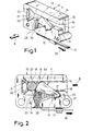
- Lock housing 10 is integrally formed.
- the web 12 serves simultaneously as a swivel bearing and as a spring element for the locking element 11.
- An actuating element for the locking element 11 is numbered 13.
- the actuating element 13 is integrally formed on the locking element 11 at 14.
- the bearing or. Lock housing 10 has an insertion channel 17 formed or limited by two parallel guide surfaces 15, 16 for a bearing or. Lock housing 10 part to be stored or locked.
- a part to be locked is designed as a bolt and designated 18.
- the locking element 11 can be pivoted laterally into the insertion channel 17 under the spring action of the web 12. With this, e.g. 2, pivoted position of the locking element 11 is the locking position of the device.
- the bolt 18 to be locked is fixed between a front, slightly curved surface 19 of the locking element 11 on the one hand and by a resilient contact surface 20 formed at the closed end of the insertion channel 17 on the other hand.
- Fig. 1, 2 and 4 make it clear that the contact surface 20 is formed by a leaf spring-like part 21 which is curved in the direction of the bolt 18 convexly curved. Behind the leaf spring-like part 21 there is a cavity 22, which enables a resilient flexibility of the leaf spring-like part 21.
- a recess 23 corresponding to the contours of the locking element 11, which - as shown in FIG. 4 - serves to receive the locking element 11 in its unlocked position.
- Fig. 4 also makes it clear that in this unlocked position, the locking element 11, a - designated by 24 - side surface of the locking element 11 also forms part of the one guide surface (16) of the insertion channel 17. In the unlocked position of the device, the locking element 11 thus facilitates the insertion of the bolt 18 into the insertion channel 17.
- a pulling force in the direction 25 is to be applied to the actuating element 13 designed as a cable pull. at the same time the spring resistance of the web 12 must be overcome.
- the actuating element 13 can be relieved, and the locking element 11 automatically returns to the locking position shown in FIG. 2 due to the spring action of the web 12.
- the locking element 11 In order to be able to absorb the forces which may act on the bolt 18 in its locking position and which it transmits to the locking element 11, the locking element 11 has on its rear side facing away from the bolt 18 to be locked a contact surface 26 which has a complementary bearing -respectively.
- Lock housing 10 trained counter abutment surface 27 cooperates such that forces exerted by the bolt 18 on the locking element 11 from the locking element 11 directly on the bearing or. Lock housing 10 are transmitted.
- the contact surface 26 on the locking element 11 is convex and the counter-contact surface 27 on the bearing or.
- Lock housing 10 is correspondingly concavely curved.
- the actuating element 13 formed on the side of the locking element (at 14) can be replaced by an actuator in the bearing or.
- the locking bolt 18 can be rotatably or rotatably - when used to lock a rear seat back on the backrest - arranged and the lock component (parts 10 -14) in this case be fixed on the body.
- an undercut 29 is formed, which in the unlocked position of the locking element (FIG. 4) with a corresponding undercut 30 in the bearing or.
- Lock housing 10 interacts. This is to prevent unintentional unlocking be prevented if the armrest against the locking element 11, connected with a rotational movement of the bolt approximately clockwise, could be taken along by friction between the bolt 18 and the locking element 11 in the unlocking direction.
- the undercut 29 prevents this and at the same time causes the locking element 11 to be fixed in the transverse direction in its unlocked position.
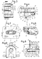
- the bolt 18 to be locked is - as can be seen in FIG. 3 - fixed in the transverse direction (double arrow 31).
- Lock housing 10 is formed into a longitudinal slot 32 which corresponds to the insertion channel 17 or the guide surfaces 15, 16 in the manner of a T-guide.
- the bolt 18 has a stepped widened end 33 which interacts with the slot 32 or is inserted into it.
- FIGS. 7-9 now show an embodiment of a locking device which is somewhat modified compared to the embodiment according to FIGS. 1-5 and which is provided in particular for use on pivotable rear seat backrests of passenger vehicles.
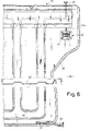
- FIG. 6 denotes a backrest sheet metal part with an integrally formed, circumferential channel 35 for — as is generally customary — attachment of a cushion cover.
- Usual meandering stiffening beads of the backrest are numbered 36 and result in the cross-sectional image of the backrest plate 34 denoted by 34 '. not shown) of the vehicle, which extends in the region of a recess, which is designated by 39 and is formed by a laterally inwardly curved configuration of the sheet metal 34.
- a corresponding axially symmetrical design of the backrest plate 34 is also provided on the right side of the backrest plate 34, not shown in FIG. 6.
- FIG. 6 In order to be able to lock the backrest or the backrest plate 34 in the folded-up normal position with the vehicle body, a locking device numbered 40 in FIG. 6 is provided.
- the components and the mode of operation of this locking device can now be seen in detail in FIGS. 7-9.
- a lock housing 10a formed as a one-piece plastic injection-molded part.
- Further components of the locking device according to FIGS. 7-9 are similar to the embodiment according to FIGS. 1-5, so that the relevant parts do not have to be described again.
- FIGS. 7-9 To clarify the correspondence in construction and mode of operation, only the relevant parts are provided with the same reference numerals as in FIGS. 1-5, only supplemented by the addition a.
- the following explanations are therefore restricted essentially only to the differences between the embodiment according to FIGS. 7-9 and that according to FIGS. 1-5.
- a fastening plate 41 is integrally formed on the lock housing 10a perpendicular to the extension thereof.
- the mounting plate 41 has four through bores 42, by means of which the lock housing 10a in the position shown in Fig. 6, e.g. by screwing, can be attached to the rear seat back 34.
- the fastening plate 41 also has a passage opening 43 which is spatially connected to the insertion channel 17a and which, as can be seen in particular from FIG. 7, is elongated.
- the passage opening 43 is provided in order to be able to insert a locking element denoted by 44 into the lock housing 10a.
- the locking element 44 is attached (in a manner not shown in more detail) on the body side, while the lock housing 10a is, as mentioned, attached to the rear seat back 34.
- the locking element 44 is not U-shaped, but rather a bolt.
- Fig. 9 makes it clear that the locking element 44 cooperates in the locking position with the lock housing 10a that the two 45 and 46 numbered U-legs of the locking device 44 come to lie on both sides of the insertion channel 17a outside the lock housing 10a. 8 and 9, on the one hand, comes into contact with the resilient contact surface 20a and, on the other hand, is engaged by the blocking element 11a which is in the blocking position.
- the locking element 44 is advantageously inserted automatically into the blocking position shown in FIGS. 7-9, ie when the rear seat backrest 34 is pivoted backwards into the upright normal position.
- the locking element 11 a is pressed against the spring action of the web 12 a by the locking element 44 upwards and engages finally behind the U-web 47 of the locking element 44 automatically into the locking position shown in FIGS. 7-9 due to the spring-loaded web 12a.
- a pulling force in the direction of arrow 48 is merely to be applied to the actuating element 13a.
- an actuating button 49 is attached to the upper end of the actuating element 13a, as can be seen in FIG.
Landscapes
- Engineering & Computer Science (AREA)
- Aviation & Aerospace Engineering (AREA)
- Transportation (AREA)
- Mechanical Engineering (AREA)
- Seats For Vehicles (AREA)
- Lock And Its Accessories (AREA)
Applications Claiming Priority (2)
| Application Number | Priority Date | Filing Date | Title |
|---|---|---|---|
| DE3513807A DE3513807C2 (de) | 1985-04-17 | 1985-04-17 | Verriegelungsvorrichtung, insbesondere für verschwenkbare Kraftfahrzeugsitze |
| DE3513807 | 1985-04-17 |
Publications (3)
| Publication Number | Publication Date |
|---|---|
| EP0198211A2 true EP0198211A2 (fr) | 1986-10-22 |
| EP0198211A3 EP0198211A3 (en) | 1988-07-20 |
| EP0198211B1 EP0198211B1 (fr) | 1990-08-08 |
Family
ID=6268328
Family Applications (1)
| Application Number | Title | Priority Date | Filing Date |
|---|---|---|---|
| EP86103184A Expired - Lifetime EP0198211B1 (fr) | 1985-04-17 | 1986-03-10 | Dispositif de support et de verrouillage notamment pour dossiers pivotants de sièges arrières de véhicule automobile |
Country Status (3)
| Country | Link |
|---|---|
| US (1) | US4711493A (fr) |
| EP (1) | EP0198211B1 (fr) |
| DE (2) | DE3513807C2 (fr) |
Cited By (2)
| Publication number | Priority date | Publication date | Assignee | Title |
|---|---|---|---|---|
| FR2626223A1 (fr) * | 1988-01-26 | 1989-07-28 | Ikeda Bussan Co | Dispositif d'accrochage du dossier rabattable d'un siege d'automobile |
| WO2015022312A1 (fr) * | 2013-08-14 | 2015-02-19 | Johnson Controls Gmbh | Unité de verrouillage pour siège de véhicule et siège de véhicule |
Families Citing this family (24)
| Publication number | Priority date | Publication date | Assignee | Title |
|---|---|---|---|---|
| DE8626167U1 (de) * | 1986-10-01 | 1986-12-18 | Adam Opel AG, 6090 Rüsselsheim | Verriegelungsvorrichtung für eine Hintersitz-Rückenlehne |
| JP3160990B2 (ja) * | 1992-02-07 | 2001-04-25 | アイシン精機株式会社 | 車両用シートスライド装置 |
| JP2764891B2 (ja) * | 1994-07-08 | 1998-06-11 | 三井建設株式会社 | 揚重装置及び、該装置を用いた構築資材の運搬方法 |
| DE19706786C1 (de) * | 1997-02-20 | 1998-10-22 | Schmidt Gmbh R | Verriegelungsvorrichtung für klappbare Rückenlehnen |
| US6491346B1 (en) * | 2000-06-01 | 2002-12-10 | Dow Global Technologies, Inc. | Seating system and method for making the same |
| US6739673B2 (en) | 2001-08-15 | 2004-05-25 | Dow Global Technologies, Inc. | Seating system |
| US7128373B2 (en) * | 2002-09-27 | 2006-10-31 | Dow Global Technologies, Inc. | Seating system and method of forming same |
| US6733078B1 (en) * | 2002-12-13 | 2004-05-11 | Fisher Dynamics Corporation | Two-position latch apparatus |
| US7250091B2 (en) * | 2003-02-13 | 2007-07-31 | Dow Global Technologies Inc | Method of forming a seating system |
| DE10321296A1 (de) * | 2003-05-13 | 2004-07-15 | Daimlerchrysler Ag | Zuglasche |
| DE102004002358B3 (de) * | 2004-01-15 | 2005-05-19 | Keiper Gmbh & Co. Kg | Verriegelungsvorrichtung für einen Fahrzeugsitz |
| US8245370B2 (en) * | 2004-03-18 | 2012-08-21 | Michigan Aerospace Corporation | Docking system |
| US7861974B2 (en) * | 2004-03-18 | 2011-01-04 | Michigan Aerospace Corporation | Docking system |
| US8240613B2 (en) * | 2004-03-18 | 2012-08-14 | Michigan Aerospace Corporation | Docking system |
| DE102004018742A1 (de) * | 2004-04-17 | 2005-11-10 | Keiper Gmbh & Co.Kg | Schliessvorrichtung, insbesondere für einen Fahrzeugsitz |
| US7393054B2 (en) * | 2005-11-17 | 2008-07-01 | Lear Corporation | Self adjusting seatback system |
| DE102006058388B4 (de) * | 2006-08-17 | 2008-06-19 | Johnson Controls Gmbh | Betätigungsvorrichtung für einen Sitz, insbesondere einen Kraftfahrzeugsitz |
| DE102008033305B4 (de) * | 2008-07-11 | 2019-06-27 | Adient Luxembourg Holding S.À R.L. | Verriegelungsvorrichtung für einen Fahrzeugsitz und Fahrzeugsitz |
| DE102008064838B3 (de) | 2008-07-11 | 2022-11-10 | Keiper Seating Mechanisms Co., Ltd. | Verriegelungsvorrichtung für einen Fahrzeugsitz |
| DE102008033303B4 (de) * | 2008-07-11 | 2015-08-20 | Johnson Controls Components Gmbh & Co. Kg | Verriegelungsvorrichtung für einen Fahrzeugsitz |
| DE102008033304B4 (de) * | 2008-07-11 | 2018-01-04 | Adient Luxembourg Holding S.à.r.l. | Verriegelungsvorrichtung für einen Fahrzeugsitz und Fahrzeugsitz |
| CN103303167B (zh) * | 2013-05-29 | 2015-08-05 | 江苏皓月汽车锁股份有限公司 | 一种汽车座椅锁 |
| US11370332B2 (en) | 2020-06-19 | 2022-06-28 | Fisher & Company, Incorporated | Latch mechanism for seat assembly |
| US12583392B1 (en) | 2023-12-06 | 2026-03-24 | David Reign Wilks, Jr. | Locakable ISOFIX connection device and method of securing an object to a vehicle seat |
Family Cites Families (11)
| Publication number | Priority date | Publication date | Assignee | Title |
|---|---|---|---|---|
| GB1099649A (en) * | 1966-02-01 | 1968-01-17 | Ford Motor Co | Locks |
| US3767244A (en) * | 1971-05-25 | 1973-10-23 | Stanley Works Pty | Locks |
| US3881758A (en) * | 1974-01-14 | 1975-05-06 | Illinois Tool Works | Window opener and latch |
| US3985380A (en) * | 1975-08-08 | 1976-10-12 | General Motors Corporation | Overcenter type latch |
| US4035877A (en) * | 1975-09-15 | 1977-07-19 | Brownson Ivan F | Buckle |
| JPS5811878Y2 (ja) * | 1977-04-20 | 1983-03-07 | アイシン精機株式会社 | 自動車用ドアロツク装置 |
| IT1115555B (it) * | 1977-09-12 | 1986-02-03 | Mecanismes Comp Ind De | Serratura particolarmente per porte di autoveicoli |
| ES240751Y (es) * | 1979-01-15 | 1979-08-16 | Dispositivo retenedor. | |
| US4408373A (en) * | 1980-09-02 | 1983-10-11 | Gateway Industries, Inc. | Buckle with integral push button spring and reaction portions |
| JPS57205239A (en) * | 1981-06-11 | 1982-12-16 | Mazda Motor Corp | Rear seat of automobile |
| DE3140002C1 (de) * | 1981-10-08 | 1983-04-14 | Adam Opel AG, 6090 Rüsselsheim | Verriegelungsvorrichtung fuer verschwenkbare Hintersitz-Rueckenlehnen von Kraftfahrzeugen |
-
1985
- 1985-04-17 DE DE3513807A patent/DE3513807C2/de not_active Expired
-
1986
- 1986-02-20 US US06/831,179 patent/US4711493A/en not_active Expired - Fee Related
- 1986-03-10 DE DE8686103184T patent/DE3673210D1/de not_active Expired - Lifetime
- 1986-03-10 EP EP86103184A patent/EP0198211B1/fr not_active Expired - Lifetime
Cited By (3)
| Publication number | Priority date | Publication date | Assignee | Title |
|---|---|---|---|---|
| FR2626223A1 (fr) * | 1988-01-26 | 1989-07-28 | Ikeda Bussan Co | Dispositif d'accrochage du dossier rabattable d'un siege d'automobile |
| WO2015022312A1 (fr) * | 2013-08-14 | 2015-02-19 | Johnson Controls Gmbh | Unité de verrouillage pour siège de véhicule et siège de véhicule |
| US9919627B2 (en) | 2013-08-14 | 2018-03-20 | Johnson Controls Gmbh | Locking unit for a vehicle seat, and vehicle seat |
Also Published As
| Publication number | Publication date |
|---|---|
| EP0198211A3 (en) | 1988-07-20 |
| EP0198211B1 (fr) | 1990-08-08 |
| DE3673210D1 (de) | 1990-09-13 |
| DE3513807C2 (de) | 1987-04-09 |
| DE3513807A1 (de) | 1986-10-23 |
| US4711493A (en) | 1987-12-08 |
Similar Documents
| Publication | Publication Date | Title |
|---|---|---|
| EP0198211B1 (fr) | Dispositif de support et de verrouillage notamment pour dossiers pivotants de sièges arrières de véhicule automobile | |
| DE2719325A1 (de) | Sicherheitsgurt-verschluss | |
| DE2316353A1 (de) | Verschlussteil fuer kraftfahrzeug-sicherheitsgurt | |
| DE3343161A1 (de) | Fahrzeug-tuergriff | |
| DE202005011297U1 (de) | Fahrzeug-Haltegriff | |
| DE102014018095A1 (de) | Kraftfahrzeugtürgriffanordnung mit Führung des Handgriffs | |
| EP0357705A1 (fr) | Dispositif de fermeture pour la jugulaire d'un casque de motocyclette. | |
| DE3510649A1 (de) | Schloss fuer sicherheitsgurte | |
| DE69502142T2 (de) | Vorrichtung zum Schnellverbinden eines Kindersitzes mit einem Kraftwagensitz | |
| EP0186830A2 (fr) | Dispositif de réglage de la hauteur pour la ferrure de renvoi d'une ceinture de sécurité | |
| DE102015221450A1 (de) | Befestigungseinrichtung mit einem Haltebügel, an dem ein Ausstattungselement mittels eines Fixiermittels vorübergehend festlegbar ist | |
| DE2814318A1 (de) | Einstellbarer verschluss, insbesondere fuer kleidungsstuecke | |
| DE2906288C2 (de) | Anbauteil zum Anschluß an eine Wandung, insbesondere Griff oder Armlehne zum Anschluß an ein Karosserieteil eines Kraftfahrzeuges | |
| DE102017009056B4 (de) | Sitzanordnung für ein Kraftfahrzeug | |
| DE2056723A1 (de) | Türschild oder Rosette | |
| DE19840642C2 (de) | Befestigungselement für einen Betätigungszug | |
| DE19943750B4 (de) | Übertragungselement zwischen einem Türgriff und einem Türschloß eines Kraftfahrzeugs | |
| DE10126687A1 (de) | Vorrichtung zum Sichern eines Sitzrückens an einem Kraftfahrzeugkörper | |
| DE2310373C3 (de) | Wischblatt für Scheiben wischanlagen von Fahrzeugen, insbesondere Kraftfahrzeugen | |
| DE8327221U1 (de) | Gurtschloß für ein Sicherheitsgurtsystem | |
| DE2441565A1 (de) | Verbindungssystem fuer zwei teile aus leicht verformbarem material und fuer dasselbe zu verwendender gleitverschlusschieber | |
| DE29502987U1 (de) | Ausklinkbares Schnappschloß | |
| DE102006059096B4 (de) | Baugruppe zur fahrzeugseitigen Befestigung eines Gurtschlosses | |
| DE1557429B2 (de) | Verschlusschnalle fuer sicherheitsgurte | |
| DE3248053A1 (de) | Loesbare, auf unterschiedliche tuerdicken einstellbare dornbefestigung fuer tuerhandhaben |
Legal Events
| Date | Code | Title | Description |
|---|---|---|---|
| PUAI | Public reference made under article 153(3) epc to a published international application that has entered the european phase |
Free format text: ORIGINAL CODE: 0009012 |
|
| AK | Designated contracting states |
Kind code of ref document: A2 Designated state(s): DE FR GB IT |
|
| 17P | Request for examination filed |
Effective date: 19870204 |
|
| PUAL | Search report despatched |
Free format text: ORIGINAL CODE: 0009013 |
|
| AK | Designated contracting states |
Kind code of ref document: A3 Designated state(s): DE FR GB IT |
|
| 17Q | First examination report despatched |
Effective date: 19890322 |
|
| ITF | It: translation for a ep patent filed | ||
| GRAA | (expected) grant |
Free format text: ORIGINAL CODE: 0009210 |
|
| AK | Designated contracting states |
Kind code of ref document: B1 Designated state(s): DE FR GB IT |
|
| ET | Fr: translation filed | ||
| GBT | Gb: translation of ep patent filed (gb section 77(6)(a)/1977) | ||
| REF | Corresponds to: |
Ref document number: 3673210 Country of ref document: DE Date of ref document: 19900913 |
|
| PLBE | No opposition filed within time limit |
Free format text: ORIGINAL CODE: 0009261 |
|
| STAA | Information on the status of an ep patent application or granted ep patent |
Free format text: STATUS: NO OPPOSITION FILED WITHIN TIME LIMIT |
|
| 26N | No opposition filed | ||
| PGFP | Annual fee paid to national office [announced via postgrant information from national office to epo] |
Ref country code: FR Payment date: 19940225 Year of fee payment: 9 |
|
| PGFP | Annual fee paid to national office [announced via postgrant information from national office to epo] |
Ref country code: GB Payment date: 19940228 Year of fee payment: 9 |
|
| ITTA | It: last paid annual fee | ||
| PGFP | Annual fee paid to national office [announced via postgrant information from national office to epo] |
Ref country code: DE Payment date: 19940513 Year of fee payment: 9 |
|
| PG25 | Lapsed in a contracting state [announced via postgrant information from national office to epo] |
Ref country code: GB Effective date: 19950310 |
|
| GBPC | Gb: european patent ceased through non-payment of renewal fee |
Effective date: 19950310 |
|
| PG25 | Lapsed in a contracting state [announced via postgrant information from national office to epo] |
Ref country code: FR Free format text: LAPSE BECAUSE OF NON-PAYMENT OF DUE FEES Effective date: 19951130 |
|
| PG25 | Lapsed in a contracting state [announced via postgrant information from national office to epo] |
Ref country code: DE Effective date: 19951201 |
|
| REG | Reference to a national code |
Ref country code: FR Ref legal event code: ST |
|
| PG25 | Lapsed in a contracting state [announced via postgrant information from national office to epo] |
Ref country code: IT Free format text: LAPSE BECAUSE OF NON-PAYMENT OF DUE FEES;WARNING: LAPSES OF ITALIAN PATENTS WITH EFFECTIVE DATE BEFORE 2007 MAY HAVE OCCURRED AT ANY TIME BEFORE 2007. THE CORRECT EFFECTIVE DATE MAY BE DIFFERENT FROM THE ONE RECORDED. Effective date: 20050310 |