EP0198220A2 - Générateur d'air chaud - Google Patents
Générateur d'air chaud Download PDFInfo
- Publication number
- EP0198220A2 EP0198220A2 EP86103299A EP86103299A EP0198220A2 EP 0198220 A2 EP0198220 A2 EP 0198220A2 EP 86103299 A EP86103299 A EP 86103299A EP 86103299 A EP86103299 A EP 86103299A EP 0198220 A2 EP0198220 A2 EP 0198220A2
- Authority
- EP
- European Patent Office
- Prior art keywords
- guide tube
- flame guide
- heat exchanger
- passage openings
- ratio
- Prior art date
- Legal status (The legal status is an assumption and is not a legal conclusion. Google has not performed a legal analysis and makes no representation as to the accuracy of the status listed.)
- Granted
Links
Images



Classifications
-
- F—MECHANICAL ENGINEERING; LIGHTING; HEATING; WEAPONS; BLASTING
- F24—HEATING; RANGES; VENTILATING
- F24H—FLUID HEATERS, e.g. WATER OR AIR HEATERS, HAVING HEAT-GENERATING MEANS, e.g. HEAT PUMPS, IN GENERAL
- F24H3/00—Air heaters
- F24H3/02—Air heaters with forced circulation
- F24H3/06—Air heaters with forced circulation the air being kept separate from the heating medium, e.g. using forced circulation of air over radiators
- F24H3/08—Air heaters with forced circulation the air being kept separate from the heating medium, e.g. using forced circulation of air over radiators by tubes
- F24H3/087—Air heaters with forced circulation the air being kept separate from the heating medium, e.g. using forced circulation of air over radiators by tubes using fluid fuel
Definitions
- the invention relates to a warm air generator with a blower, which presses the circulating air to be heated via a heat exchanger through which the flue gases of a burner-heated combustion chamber flows, into a blow-out chamber, a duct connecting the blower to the blow-out chamber and bypassing the heat exchanger being provided for part of the circulating air and a flame guide tube, especially for this warm air generator.
- Such a warm air generator is known from DE-PS 30 39 065 and has proven itself in practice. Nevertheless, there have been performance problems in certain applications, and an object of the invention is to improve the efficiency of such a mixture of more heated (bypassed through the heat exchanger) and less heated (bypassed) circulating air blowing devices.
- the (bypass) channel surrounds the combustion chamber and the heat exchanger on all sides.
- the circulating air through the duct not only flushes the partition facing the combustion chamber from all sides, but also cools all the outside walls of the device.
- the channel is preferably formed by a jacket concentrically surrounding the vertical cylindrical combustion chamber and the coaxially adjoining heat exchanger, and by the side walls of a housing enclosing all components, an annular channel being formed between the combustion chamber and jacket for the circulating air flowing through the heat exchanger.
- This device structure which is centrally symmetrical in cross-section, manages with a minimum of base area and has an essentially uniform temperature distribution all around to the central axis.
- the design of the duct as an annular space surrounding the combustion chamber and the heat exchanger on all sides, which takes up about a third of the total amount of air required by the blower and mixes the bypass air flowing through it with a concentric inflow of the air heated by the heat exchanger, optimizes the thermal output and thus the Energy utilization.
- bypass air rising in the duct cools the outer walls of the hot air generator and, as a welcome side effect, prevents it from overheating.
- the invention further relates to a flame guide tube for a warm air generator, preferably the one described here.
- This flame guide tube is suitable for a warm air generator with a blower, which presses the circulating air to be heated via a heat exchanger through which the flue gases of a burner-heated combustion chamber flows, into a blow-out chamber, a channel connecting the blower with the blow-out chamber and bypassing the heat exchanger for part of the circulating air is, such as the hot air generator mentioned in DE-PS 30 39 065.
- a warm air generator with a blower, which presses the circulating air to be heated via a heat exchanger through which the flue gases of a burner-heated combustion chamber flows, into a blow-out chamber, a channel connecting the blower with the blow-out chamber and bypassing the heat exchanger for part of the circulating air is, such as the hot air generator mentioned in DE-PS 30 39 065.
- this and other known warm air generators are large and need to be priced accordingly.
- the combustion of the fuel (mostly oil) and the heat generation are also incomplete, so the use of energy is imperfect. For reduction and optimization, it
- Flame guide tubes for improving the fuel utilization are known for large boiler combustion plants. These consist of fireclay, highly heat-resistant ceramics, silicate fibers and the like and are usually designed as a pot into which the burner flame is directed and from which the heating gases emerge again against the direction of entry after flowing out against the pot bottom.
- Another object of the invention is therefore to provide a flame guide tube which is suitable for use in warm air generators.
- the flame guide tube has a tube wall with a longitudinal slot on the underside in the installed position and parallel to the tube longitudinal axis.
- the flame guide tube according to the invention enables a compact, space-saving design of the warm air generator.
- the energy is generated by optimal combustion and thus heating fabric utilization increased.
- the flame guide tube glows in the operating state, causing soot particles and the like. are burned and the environmental impact is reduced.
- Heat backflow and heat dissipation are optimized by diverting the hot gases downwards and outwards; Improved flame management and distribution ensure more even and lossless heat transfer. This is particularly assisted by additional through openings provided in the wall of the flame guide tube.
- the flame guide tube can be attached by simply screwing it into the combustion chamber and can therefore be easily serviced or replaced.
- the shape of the longitudinal slot and, if necessary, the number, size and shape of the passage openings are modified.
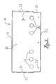
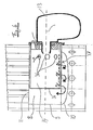
- the essentially box-shaped hot air generator consists of a lower blower part 1 and an upper heating part 2 (FIGS. 1 and 2), which are separated by an intermediate floor 3; however, the intermediate floor 3 has an opening (not shown) for the outlet of a blower 4, which draws in the circulating air from the room through grilles 5.
- the device has a continuous cross-section over the parts 1, 2, apart from corners that are chamfered to a certain extent, which also determines the base area.
- the walls of the housing designated as a whole by 6 consist of sheet steel.
- a pot-shaped combustion chamber 8 is arranged concentrically to the vertical central axis 7 (FIG. 4), which consists of a cylinder housing 9 with a boiler bottom 10 on the underside and an end plate 11 on the top.
- a flame guide tube 14 Concentric to the horizontal axis 12 of the burner 13, which intersects the central axis 7 of the device, is arranged in the combustion chamber 8 a flame guide tube 14 made of heat-resistant stainless steel, which will be explained in more detail later, and is closed off from the carrier flange 15 for the burner 13 by a circular Stimbtech 16.
- the flame guide tube 14 is cut open at the bottom parallel to the axis 12 and angled to form legs 18 to form a longitudinal slot 17.
- the hot flue gases generated by the burner flame in the flame guide tube 14 enter the combustion chamber 8 through the longitudinal slot 17.
- the end plate 11 pass through the tubes 19 of an overall designated 20 heat exchanger.
- the tubes 19 are arranged concentrically to the axis 7, so that the heat exchanger 20 is in turn arranged coaxially with the combustion chamber 8.
- the tubes 19 open into an annular flue gas collector 21, on which the flue gas connector 22 attaches
- a jacket 23 concentric with the axis 7 surrounds the heating unit consisting of the combustion chamber 8, the heat exchanger 20 and the flue gas collector 21. Together with this, it forms an annular channel 24 for the largest part of the circulating air, which is conveyed by the blower 4 through the intermediate floor 3 against the heating unit.
- This air passes through the ring channel 24 to the heat exchanger 20 and from there past the flue gas collector 21 into the blow-out chamber 25, from which it flows back through lamellar grids 26 into the surrounding space.
- part of the circulating air supplied by the blower 4 passes through bores 27, which are arranged just above the intermediate floor 3 in the jacket 23, into which the heating unit and in particular the heat exchanger 20 are bypassed - (bypass) channel 28, which is outside of the walls of the Housing 6 is defined.
- the bypass channel is designed as an annular space 28 surrounding the combustion chamber 8 and the heat exchanger 20 on all sides.
- the part of the air flowing through it (about 1/3 of the delivery volume of the blower 4) cools both the jacket 23 and the walls of the housing 6. Because of the large volume of air in the annular space 28, this is The heating of the bypass air is low overall and is only a few ° C.
- This bypass air is mixed in the blow-out chamber 25 with the other, larger and primarily heated in the heat exchanger 20 air fraction, the concentric inflow of the bypass air to the heated air through an adjusted annular gap between the heat exchanger 20 and jacket 23 for good mixing and one ensures uniform outlet temperature.
- the combustion chamber 8 can also have a square cross section; the same applies to the flue gas collector 21. However, the cylindrical cross-sectional shape of the jacket 23 remains unaffected.
- the flame guide tube 14 arranged in the combustion chamber 8 is formed by an essentially rectangular wall plate 30, which is shown in FIG. 5 in the state not yet bent to the flame guide tube 14.
- the wall plate 30 is preferably approximately 0.5 to 2 mm thick and consists of high-temperature stainless steel.
- a first longitudinal edge 31 of the wall plate 30 forms the edge of the flame guide tube 14 facing the burner 13.
- the opposite, second longitudinal edge 32 of the wall plate 30 serves to fix the end plate 16.
- the shape of the wall plate is the second longitudinal edge 32 somewhat shorter than the first longitudinal edge 31, since the legs 18 of the flame guide tube 14 formed by the transverse edges 33 of the wall plate 30 do not pass through to the end of the flame guide tube 14 on the burner side. As shown in Fig. 7, however, it can also be provided that the legs 18 pass over the entire length of the flame guide tube 14 and the longitudinal edges of the wall plate 30 are of the same length.
- this kink line 34 forms the continuation of an edge section 35 lying further inward with respect to the transverse edge 33, in which no legs 18 are formed.
- the wall plate 30 has two symmetrically arranged groups of three passage openings 36, which are arranged so that after bending the wall plate 30 to the flame guide tube 14, all the passage openings 36 in the same cross-sectional plane and each pair in a longitudinal plane of the Flame guide tube 14 are opposite. These passage openings 36 are arranged displaced from the center of the wall plate 30 in the direction of the transverse edges 33, so that they lie only in the lower region of the flame guide tube 14. The upper apex region of the flame guide tube 14 is therefore completely closed. In the part of the flame guide tube which is seen from the apex region, there are first exit possibilities for hot gases in the form of the passage openings 36; however, the mass of the hot gases, as indicated overall in FIG. 6 by the position and number of arrows A, exits through the longitudinal slot 17 into the combustion chamber 8.
- Screw holes 37 are furthermore formed in the wall plate 30 and, after the flame guide tube 14 has been inserted into the combustion chamber 8, serve to fasten the flame guide tube 14 (FIG. 7).
- the flame guide tube 14 its length and its diameter are in a ratio of 2.15.
- the ratio of the diameter to the leg width, i.e. the distance between the crease line 34 and the transverse edge 33 of the wall plate 30 is 28.
- the length of the flame guide tube 14 is related to the width of the longitudinal slot 17, i.e. the distance between the opposing legs 18, such as 17.5: 1.
- the diameter of the flame guide tube 14 relates to the width of the longitudinal slot 17 as 8: 1.
- the ratio of the width of the longitudinal slot 17 to the width of the legs 18 is preferably between 3.5 and 3.9.
- the ratio of the flame guide tube diameter to the diameter of the through openings 36 is 5.6 and the ratio of the flame guide tube length to the diameter of the through openings 36 is 12.
- the width of the longitudinal slot 17 is related to Diameter of the passage openings 36 as 0.7: 1. In this preferred embodiment, all passage openings 36 have the same diameter; this is referred to above.
- the ratio of the passage area of the longitudinal slot 17 to the total area of all passage openings 36 is particularly important for optimal flame guidance and distribution to the total opening area formed by these. In the particularly preferred embodiment described, this ratio is between 20 and 22.
Landscapes
- Engineering & Computer Science (AREA)
- Physics & Mathematics (AREA)
- Thermal Sciences (AREA)
- Chemical & Material Sciences (AREA)
- Combustion & Propulsion (AREA)
- Mechanical Engineering (AREA)
- General Engineering & Computer Science (AREA)
- Air Supply (AREA)
- Gas Burners (AREA)
- Respiratory Apparatuses And Protective Means (AREA)
- Manufacturing Of Electric Cables (AREA)
- Instantaneous Water Boilers, Portable Hot-Water Supply Apparatuses, And Control Of Portable Hot-Water Supply Apparatuses (AREA)
Priority Applications (1)
| Application Number | Priority Date | Filing Date | Title |
|---|---|---|---|
| AT86103299T ATE56088T1 (de) | 1985-03-14 | 1986-03-12 | Warmlufterzeuger. |
Applications Claiming Priority (2)
| Application Number | Priority Date | Filing Date | Title |
|---|---|---|---|
| DE19853509106 DE3509106A1 (de) | 1985-03-14 | 1985-03-14 | Warmlufterzeuger mit einem den waermetauscher umgehenden kanal |
| DE3509106 | 1985-03-14 |
Publications (3)
| Publication Number | Publication Date |
|---|---|
| EP0198220A2 true EP0198220A2 (fr) | 1986-10-22 |
| EP0198220A3 EP0198220A3 (en) | 1987-03-25 |
| EP0198220B1 EP0198220B1 (fr) | 1990-08-29 |
Family
ID=6265161
Family Applications (1)
| Application Number | Title | Priority Date | Filing Date |
|---|---|---|---|
| EP19860103299 Expired - Lifetime EP0198220B1 (fr) | 1985-03-14 | 1986-03-12 | Générateur d'air chaud |
Country Status (3)
| Country | Link |
|---|---|
| EP (1) | EP0198220B1 (fr) |
| AT (1) | ATE56088T1 (fr) |
| DE (2) | DE3509106A1 (fr) |
Family Cites Families (7)
| Publication number | Priority date | Publication date | Assignee | Title |
|---|---|---|---|---|
| BE509271A (fr) * | ||||
| BE474839A (fr) * | ||||
| FR994662A (fr) * | 1949-09-05 | 1951-11-21 | Neu Ets | Appareil générateur d'air chaud |
| DE1147738B (de) * | 1954-09-13 | 1963-04-25 | Dravo Corp | Lufterhitzer fuer Raumbeheizung |
| DE1970160U (de) * | 1967-07-22 | 1967-10-12 | Friedrich Graepel | Warmluftofen. |
| DE3039065C2 (de) * | 1980-10-16 | 1984-05-24 | Nordklima Lohner Klimatechnik GmbH, 2842 Lohne | Warmluft-Heizvorrichtung |
| DE3048044C2 (de) * | 1980-12-19 | 1983-06-09 | Helmut Dipl.-Chem. 8000 München Ulrich | Flammrohr aus hitzebeständigem Werkstoff für Brenner, insbesondere Ölbrenner |
-
1985
- 1985-03-14 DE DE19853509106 patent/DE3509106A1/de not_active Withdrawn
-
1986
- 1986-03-12 AT AT86103299T patent/ATE56088T1/de not_active IP Right Cessation
- 1986-03-12 DE DE8686103299T patent/DE3673679D1/de not_active Expired - Fee Related
- 1986-03-12 EP EP19860103299 patent/EP0198220B1/fr not_active Expired - Lifetime
Also Published As
| Publication number | Publication date |
|---|---|
| DE3673679D1 (de) | 1990-10-04 |
| EP0198220B1 (fr) | 1990-08-29 |
| EP0198220A3 (en) | 1987-03-25 |
| DE3509106A1 (de) | 1986-12-11 |
| ATE56088T1 (de) | 1990-09-15 |
Similar Documents
| Publication | Publication Date | Title |
|---|---|---|
| DE3633236C2 (fr) | ||
| DE3012588C2 (de) | Strahlungsbrenner, insbesondere für gasförmigen Brennstoff | |
| DE3628293A1 (de) | Heizkessel fuer die verbrennung fluessiger und/oder gasfoermiger brennstoffe | |
| EP0128463A2 (fr) | Appareil de chauffage des locaux pour des locaux de petite dimension | |
| EP0198220A2 (fr) | Générateur d'air chaud | |
| EP0209703B1 (fr) | Cartouche incandescente pour fours, en particulier pour chaudières ainsi que four avec une telle cartouche | |
| DE9310646U1 (de) | Vorrichtung zur Beheizung von Räumen | |
| DE19538701C2 (de) | Warmlufterzeuger | |
| DE3438320C2 (fr) | ||
| DE69001197T2 (de) | Kesselglied fuer niedertemperatur-heizkessel. | |
| DE3302611C2 (de) | Befeuerter Lufterhitzer | |
| EP0706013B1 (fr) | Echangeur de chaleur à gaz | |
| DE1997457U (de) | Brennkammer fuer heizgeraete, insbesondere gasluftheizgeraete. | |
| DE2742745B2 (de) | Wärmetauscher | |
| AT401566B (de) | Heizeinrichtung | |
| DE1812584C3 (de) | Trocknungsvorrichtung zum Trocknen von Stückgut | |
| DE2924049A1 (de) | Waermetauscher fuer warmwasser-heizungsanlagen | |
| DE712515C (de) | Mit Luefter versehener gas- oder oelbeheizter Lufterhitzer | |
| DE3422298A1 (de) | Direktbefeuerter lufterhitzer mit heizaggregat fuer eine warmluftheizung | |
| DE3608196A1 (de) | Flammenfuehrungsrohr | |
| DE69200149T2 (de) | Gasbetriebener Wasserrohrkessel. | |
| AT396172B (de) | Gasraumheizer | |
| DE8236459U1 (de) | Gerät zum Wärmeaustausch zwischen zwei gasförmigen Medien | |
| DE7411296U (de) | Wärmetauscher mit einseitig offener Brennkammer | |
| DE7305328U (de) | Mehrzugkessel |
Legal Events
| Date | Code | Title | Description |
|---|---|---|---|
| PUAI | Public reference made under article 153(3) epc to a published international application that has entered the european phase |
Free format text: ORIGINAL CODE: 0009012 |
|
| AK | Designated contracting states |
Kind code of ref document: A2 Designated state(s): AT BE DE FR IT NL |
|
| PUAL | Search report despatched |
Free format text: ORIGINAL CODE: 0009013 |
|
| AK | Designated contracting states |
Kind code of ref document: A3 Designated state(s): AT BE DE FR IT NL |
|
| 17P | Request for examination filed |
Effective date: 19870508 |
|
| 17Q | First examination report despatched |
Effective date: 19880421 |
|
| RAP3 | Party data changed (applicant data changed or rights of an application transferred) |
Owner name: NORDKLIMA LUFT- UND WAERMETECHNIK GMBH |
|
| GRAA | (expected) grant |
Free format text: ORIGINAL CODE: 0009210 |
|
| AK | Designated contracting states |
Kind code of ref document: B1 Designated state(s): AT BE DE FR IT NL |
|
| REF | Corresponds to: |
Ref document number: 56088 Country of ref document: AT Date of ref document: 19900915 Kind code of ref document: T |
|
| RAP4 | Party data changed (patent owner data changed or rights of a patent transferred) |
Owner name: NORDKLIMA LUFT- UND WAERMETECHNIK GMBH |
|
| REF | Corresponds to: |
Ref document number: 3673679 Country of ref document: DE Date of ref document: 19901004 |
|
| ET | Fr: translation filed | ||
| ITF | It: translation for a ep patent filed | ||
| ITTA | It: last paid annual fee | ||
| PLBE | No opposition filed within time limit |
Free format text: ORIGINAL CODE: 0009261 |
|
| STAA | Information on the status of an ep patent application or granted ep patent |
Free format text: STATUS: NO OPPOSITION FILED WITHIN TIME LIMIT |
|
| 26N | No opposition filed | ||
| PGFP | Annual fee paid to national office [announced via postgrant information from national office to epo] |
Ref country code: FR Payment date: 19960318 Year of fee payment: 11 |
|
| PGFP | Annual fee paid to national office [announced via postgrant information from national office to epo] |
Ref country code: BE Payment date: 19960321 Year of fee payment: 11 |
|
| PGFP | Annual fee paid to national office [announced via postgrant information from national office to epo] |
Ref country code: AT Payment date: 19960325 Year of fee payment: 11 |
|
| PGFP | Annual fee paid to national office [announced via postgrant information from national office to epo] |
Ref country code: NL Payment date: 19960328 Year of fee payment: 11 Ref country code: DE Payment date: 19960328 Year of fee payment: 11 |
|
| PG25 | Lapsed in a contracting state [announced via postgrant information from national office to epo] |
Ref country code: AT Effective date: 19970312 |
|
| PG25 | Lapsed in a contracting state [announced via postgrant information from national office to epo] |
Ref country code: BE Effective date: 19970331 |
|
| BERE | Be: lapsed |
Owner name: NORDKLIMA LUFT- UND WARMETECHNIK G.M.B.H. Effective date: 19970331 |
|
| PG25 | Lapsed in a contracting state [announced via postgrant information from national office to epo] |
Ref country code: NL Effective date: 19971001 |
|
| PG25 | Lapsed in a contracting state [announced via postgrant information from national office to epo] |
Ref country code: FR Free format text: LAPSE BECAUSE OF NON-PAYMENT OF DUE FEES Effective date: 19971128 |
|
| NLV4 | Nl: lapsed or anulled due to non-payment of the annual fee |
Effective date: 19971001 |
|
| PG25 | Lapsed in a contracting state [announced via postgrant information from national office to epo] |
Ref country code: DE Effective date: 19971202 |
|
| REG | Reference to a national code |
Ref country code: FR Ref legal event code: ST |
|
| PG25 | Lapsed in a contracting state [announced via postgrant information from national office to epo] |
Ref country code: IT Free format text: LAPSE BECAUSE OF NON-PAYMENT OF DUE FEES;WARNING: LAPSES OF ITALIAN PATENTS WITH EFFECTIVE DATE BEFORE 2007 MAY HAVE OCCURRED AT ANY TIME BEFORE 2007. THE CORRECT EFFECTIVE DATE MAY BE DIFFERENT FROM THE ONE RECORDED. Effective date: 20050312 |